97763C (Rev. G - 3/04)
ESWA8*1G ESWA8*3GJO ESWA13*3GJO ESWDA*C
PAGE 3
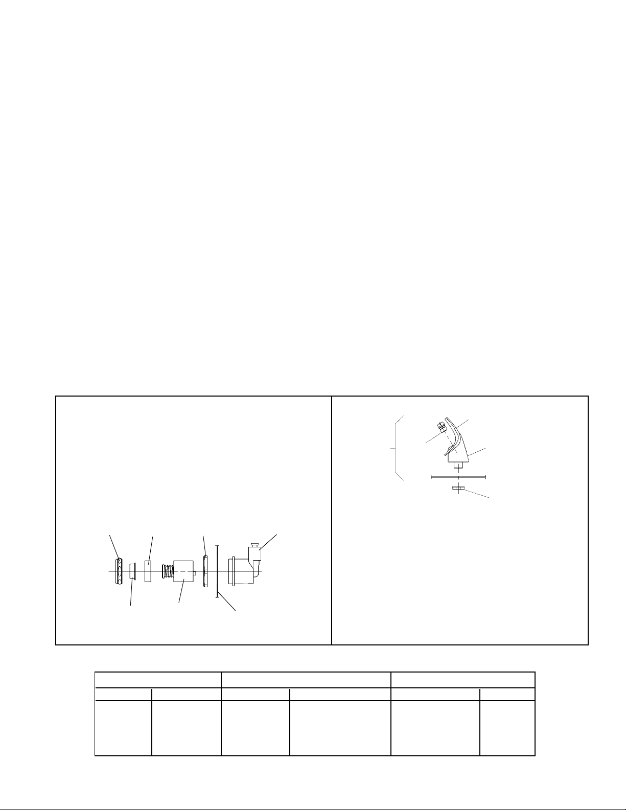
FIG. 3
Stream height is factory set at 35 PSI. If supply pressure varies greatly from this,
remove items 31 & 32 and adjust screw on item 34. Clockwise adjustment will raise stream and counter-
clockwise adjustment will lower stream. For best adjustment, stream should hit basin approximately
6-1/2" (165mm) from bubbler.
La altura del chorro se determina en la fábrica a 35 PSI. Si la presión del suministro varía demasiado de
este valor, ajuste el tornillo, sacando
los Artículos 31 y 32, y ajuste el tornillo en el Artículo 34. El ajuste en el sentido de las
agujas del reloj elevará el chorro y contra el sentido de las agujas del reloj lo bajará. Para un mejor ajuste,
el chorro deberá pegar en el estanque a
una distancia de aproximadamente 6½ (165mm) del borboteador.
Le niveau découlement est réglé en usine à 35 PSI. Si la pression varie beaucoup de ce point, retirez les
articles 31 et 32 et ajustez la vis de larticle 34. Si vous ajustez dans le sens des aiguilles dune montre, le
jet augmentera et dans le sens contraire, le jet diminuera. Le meilleur ajustement est lorsque le jet frappe
le bassin à environ 6-1/2" (165mm) du barboteur.
NOTE:
WHEN INSTALLING REPLACEMENT BUBBLER
AND PEDESTAL, TIGHTEN NUT (ITEM 12) ONLY
TO HOLD PARTS SNUG IN POSITION.
DO NOT OVER TIGHTEN.
NOTA:
CUANDO SE INSTALE EL BORBOTEADOR DE
REPUESTO Y EL PEDESTAL, APRIETE LA
TUERCA (ARTICULO 12) SOLAMENTE PARA
SOSTENER LAS PIEZAS EN SU POSICIÓN.
NO APRIETE EMASIADO.
NOTE:
LORSQUE VOUS INSTALLEZ UN NOUVEAU
BARBOTEUR ET SOCLE, RESSERREZ LÉCROU
(ARTICLE 12) SEULEMENT SUFFISAMMENT POUR
GARDER LES PIÈCES BIEN EN PLACE.
NE PAS TROP SERRER.
BASIN
ESTANQUE
BASSIN
IMPORTANT
ALL SERVICE TO BE PERFORMED
BY AN AUTHORIZED SERVICE
PERSON
IMPORTANTE
TODO EL SERVICIO DEBERÁ SER
EFECTUADO POR UNA PERSONA DE
SERVICIO AUTORIZADA
IMPORTANT
TOUT ENTRETIEN DOIT ÊTRE EFFECTUÉ
PAR UN REPRÉSENTANTAUTORISÉ
INSTALLATION DU SIPHON ET DU
SUPPORT DE SUSPENSION
1) Retirez les supports de suspension à larrière du
refroidisseur en enlevant les vis.
2) Installez les supports et le siphon tel quindiqué à la
fig. 1.
NOTE : Les supports de suspension DOIT être bien
retenu en place. Ajoutez des ferrures de fixation si le
mur noffre pas le soutien voulu.
IMPORTANT :
Ancrez solidement le support au mur à laide des six
(6) trous de fixation dun diam. 1/4 po.
3) Installez la soupape droite dans le tuyau de D.E. 3/
8".
HANGER BRACKETS & TRAP
INSTALLATION
1) Remove hanger brackets fastened to back
of cooler by removing screws.
2) Mount the hanger brackets and trap as
shown in Figure 2.
NOTE: Hanger Brackets and trap MUST be
supported securely. Add fixture support
carrier if wall will not provide adequate sup-
port.
IMPORTANT:
Anchor hanger securely to wall using all six
(6) 1/4 in. dia. mounting holes.
3) Install straight valve for 3/8" O.D. unplated
copper tube.
INSTALACIÓN DE FIJADOR DE
SUSPENSIÓN Y DEL PURGADOR
1) Quite los fijadores de suspensión sujetados a la parte
posterior del enfriador quitando los tornillos.
2) Monte los fijadores de suspensión y el purgador mostrado
en la Fig. 2.
NOTA: Los fijadores de suspensión DEBE de ser sostenido
con seguridad. Coloque portadores de soporte de
instalaciones fijas si la pared no proveerá un soporte
adecuado.
IMPORTANTE:
Ancle el suspensor de forma segura a la pared usando
todos los seis (6) agujeros de montaje de 1/4" de diámetro.
3) Instale la válvula directa para el tubo de 3/8" de diámetro
externo.
INSTALLATION DU REFROIDISSEUR
4) Installez le refroidisseur sur les supports de sus-
pension en vous assurant que ceux-ci sont bien
accrochés au cadre et au bassin.
5) Retirez le panneau daccès sous le refroidisseur
et mettez-le de côté.
6) Connectez lalimentation en eau--Voir note 3 des
instructions générales et le refroidisseur--voir la
note 4 de Manuel de les Directives Generales
7) Retirez lécrou coulissant et le joint du siphon et
installez-les sur la conduite résiduaire du
refroidisseur en vous assurant que le bout de la
conduite entre bien dans le siphon. Installez lécrou
coulissant et le joint au siphon et resserrez bien.
INSTALACIÓN DEL ENFRIADOR DE AGUA
4) Suspenda los enfriadores en los fijadores de suspensión.
Verifique que el fijador de suspensión haya trabado bien
en las ranuras que se encuentran en la parte trasera de
cada enfriador.
5) Saque el panel de acceso en la parte de abajo del enfriador
y colóquelos a un lado.
6) Conectar el tubo de entrada de agua--Ver la Nota 4 en las
Instrucciones Generales
7) Quite la tuerca de retención y el obturador del purgador y
instálelos en el tubo de desagüe asegurándose que la parte
final del tubo de desagüe calce en el purgador. Ensamble
la tuerca de la ranura y el obturador y apriete en forma
segura.
INSTALLATION OF COOLER
4) Hang the cooler on the hanger brackets.
Be certain the hanger brackets are engaged
properly in the frame and wrapper.
5) Remove the access panel on the underside
of the cooler and set it aside.
6) Connect water inlet line--See Note 4 of Gen-
eral Instructions.
7) Remove the slip nut and gasket from the
trap and install them on the cooler waste
line making sure that the end of the waste
line fits into the trap. Assemble the slip nut
and gasket to the trap and tighten securely.
PUESTA EN MARCHA
Ver también las Instrucciones Generales
8) Vuelva a colocar el panel de acceso y asegúrelo apretando
otra vez todos los tornillos.
MISE EN MARCHE
Voir aussi les Instructions Générales
8) Replacez le panneau daccès et fixez-le bien en
place en resserrant toutes les vis.
START UP
Also See General Instructions
8) Replace the front panel and secure by retight-
ening all screws.
FIG. 4
10
11
12
89
WRAPPER
ENVOLTURA
COUVRE-JOINT
34
32
3331 35 36
COLOR TABLE
PANEL COLOR Item No. 37 Part No.
Gray Beige
Almond
Stainless Steel
Sandalwood
Granite
Light Gray
COLOR DEL PANEL
21017C
21481C
21013C
21480C
27208C
27209C
Crema grisáceo
Almendra
Acero inoxidable
Madera de sándalo
Granito
Gris Claro
ARTICULO No. 37 PIEZA No.
21017C
21481C
21013C
21480C
27208C
27209C
COULEUR DU PANNEAU
Gris beige
Amande
Acier inoxydable
Santal
Granite
Gris Clair
21017C
21481C
21013C
21480C
27208C
27209C
Article 37 Pièce
TABLA DE LOS COLORES TABLE DE COULEURS