ELKHART BRASS EB-500-X User manual
EB# 98601000 REV REL
1
DIGITAL
FLOWMETER
FRC Document Number:
XE-FTD100LPM-R0A
Elkhart Brass Mfg. Co., Inc.
www.elkhartbrass.com
1302 W. Beardsly Ave., Elkhart, IN 46514
TEL 1-574-295-8330 TOLL FREE 1-800-346-0250
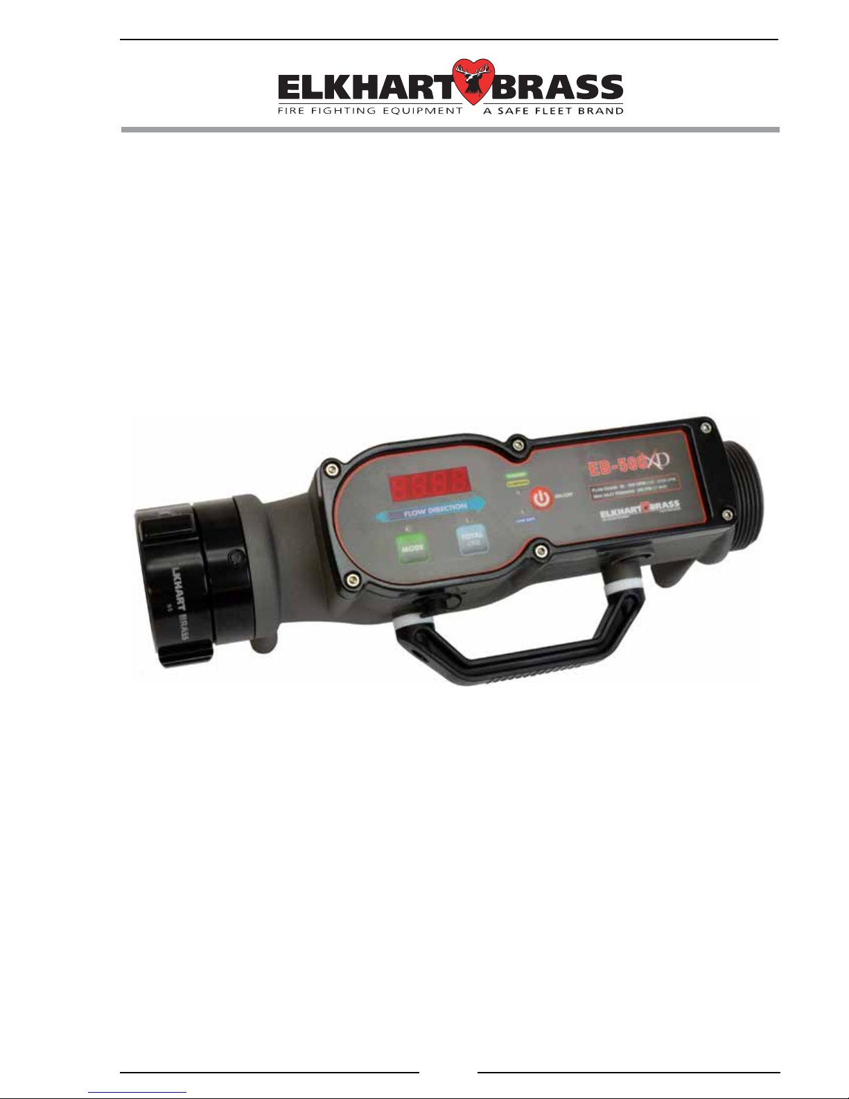
MODEL EB-500-XD
REV. 18DEC14

EB# 98601000 REV REL
2
QUICK START
1. Charge the BATTERY:
Plug in the external power supply cable to the meter and lock it with a ¼ turn
clockwise, and then plug the supply into a suitable wall outlet. Press and release
ON/OFF to turn on the display. TheAMBER charging indicator will turn GREEN
when fully charged, after a maximum of 2 ½ hours (or sooner, depending on the
status of the battery charging level). The meter will charge the internal battery,
even if the unit is turned OFF.
2. Measure the FLOW:
Maketightupstreamanddownstreamconnections,observingtheblueow
directionarrowonthemeter.TurnthemeterONandreadthevolumeowrate
on the display, in the units which the meter was calibrated (GPM or LPM).
3. Measure the TOTAL:
PressandreleaseTOTALtoseethetotalow(x100)sincelastreset.Pressand
hold TOTAL to manually reset it to zero; or simply press and release TOTAL to
returntothecurrentow.Themetermayalsobeprogrammedtoautomatically
reset to zero every time it is turned ON.
Typically, the unit may be used for 10 hours. The blue LOW BATT indicator
will light when the battery becomes depleted and needs a recharge. When
deeply depleted, the unit will not function until the power supply is connected,
but then can be used immediately.
The EB-500-XD is a precision instrument that has been designed to be simple
to operate. For complete details on the Specications, Operation, Features,
Programming, Calibration and Flowmeter Charging, read through each section
of this manual.

EB# 98601000 REV REL
3
CONTENTS
Table of Contents
QUICK START........................................................................................................... 2
CONTENTS................................................................................................................ 3
INTRODUCTION ...................................................................................................... 5
Overview................................................................................................................ 5
Features.................................................................................................................. 5
Specications......................................................................................................... 6
GENERAL DESCRIPTION ....................................................................................... 7
Components ........................................................................................................... 7
OPERATION .............................................................................................................. 8
Controls and Indicators.......................................................................................... 9
Program Features ................................................................................................. 10
TOTAL Button..................................................................................................... 10
PROGRAMMING .................................................................................................... 11
Inputs ................................................................................................................... 11
DisplayModuleIdenticationMode................................................................... 11
Program Access Mode ......................................................................................... 12
Program Code Descriptions................................................................................. 14
CALIBRATION........................................................................................................ 17
Flow Calibration, Single Point (Code 321) ......................................................... 17
Flow Calibration, Multiple Point (Code 322)...................................................... 18
FLOWMETER CHARGING.................................................................................... 19

EB# 98601000 REV REL
4
List of Tables
Table 1. Program Code Quick Reference ................................................................ 13
List of Figures
Figure 1. Components................................................................................................ 7
Figure 2. Controls and Indicators............................................................................... 9
Figure 3. Charging ................................................................................................... 19

EB# 98601000 REV REL
5
INTRODUCTION
Overview
Thedigitalowmeterhasa4-digitLEDdisplaywithdaylightbrightdigits0.56
inch high. The meter electronics are self-contained and all program features are accessed
via pushbutton switches on the front of the display.
Theportable500GPMowmeterwasdesignedtoconnecttothereapparatusin
theeld,andthisallowsforexibilityintestingapplications.Thisowmeterdisplays
owratesandthetotalizationofow.Flowrateinformationisprovidedbyapaddlewheel
typeowsensor,whichishousedinternally.Thisinformationisprocessedandshown
on the digital display.
Additionally, in the identication mode, the display shows the serial number,
manufactured date and software revision. In the program access mode, the display
shows program options and operator input selections. Selections are made using two
pushbutton switches on the front of the display module. The device also has all controls
and indicators on the front: including the battery charging status, ON/OFF pushbutton,
Low Battery Indicator, MODE, TOTAL buttons and TOTAL indicator.
Features
LED Display Brightness Automatically Adjusts for Lighting Environment
Single Point and Multiple Point Flow Rate Calibration
Pressure Port for Optional External Gauge (Not Provided)
Threads - 2.5"NH (Standard). Others available upon request.
Integrated, Rechargeable NiMH Battery with Low Battery Indicator
Quick Charge High Capacity Battery
Totalizer Flow Function with Programmable Auto-Reset
Programmable High and Low Flow Warnings
Charging LED Indicator
Portable for Easy Transport (Balanced Weight for Stability)
Unit can be Tilted forward onto the Handle for Easy Angled Viewing
Waterproof, Durable and Rugged for Tough Applications

EB# 98601000 REV REL
6
Specications
Display Module
Supply Voltage: 12 to 29VDC
External Current: 2 Amps Maximum @ 15 VDC; 30 Watts
Universal Input: 15V Power Supply (Provided)
(Optional Methods of Charging Available)
Dimensions:
Length 16 3/8"
Width 6"
Height 5 7/8"
Weight 8.40 lbs.
Flow Sensor (Integral)
Type: Paddlewheel
Sensor Material: Acetal (Delrin) with Stainless Steel (316) Shaft
Flow Range: 30–500 GPM (120–2000 LPM)
Pressure (Maximum): 250 PSI (17 BAR)
Battery (Integral)
Type: NiMH
Number of Cells: 6 Series
Voltage: 7.2 Nominal
Features: Current Monitoring
Thermal Monitoring
Input Voltage Monitoring
Input Surge Suppression Monitoring
Run Time: Up to 10 hours possible
Recharge Time: 2.5 hours fast-charge (typical)
EB# 98601000 REV REL
7
GENERAL DESCRIPTION
Components
Thebasicowmeterkitconsistsofthefollowingcomponents:
EB-500-XD Flowmeter (2.5" NH)
Charging Wall Power Supply
Protective Case
EB-500-XD Operator's Manual
Additional Kits and Options are Available
Portable Flowmeter
Thisrugged,portableowmeteriswaterproofandwasdesignedtobeintuitive,easy
tooperateandhaveunsurpassedaccuracy.Properplacementoftheowmeterisessential
for accuracy and there should not be any elbows, tees or valves immediately upstream.
Charging Methods
Forchargingand/oroperationoftheowmeter,awalloutlettransformerwith
cable is supplied.
NOTE:Theowmetermaybeusedwhilepluggedinandcharging.Optionalcar
charger available.
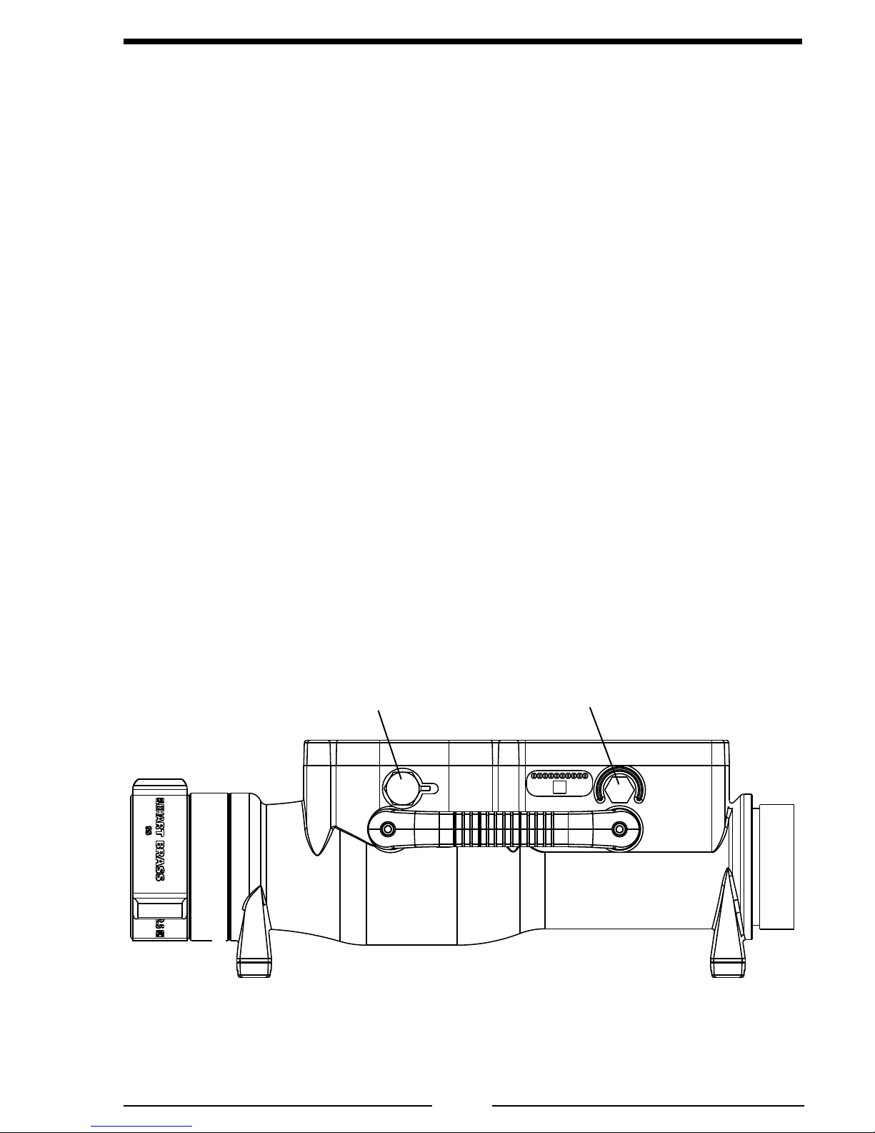
Figure 1. Components
Charging Port
(12/24 VDC) Vent
Side View

EB# 98601000 REV REL
8
OPERATION
Onpower-uptheowmeterisinnormaloperatingmode.Informationfromapaddlewheel
typeowsensorisprocessedanddisplayed.
TheEB-500-XDportableowmeterissimpleandintuitivetooperate.Thefollowing
steps will be useful for general operation, and are only examples of how it may be used
(not exact scenarios).
1. Make tight upstream and downstream connections to the coupling and threaded
ends. Observe the blue arrow in the FLOW Display for direction.
2. Press and release the ON/OFF button to activate the unit. The display will
lightupshowingtheowrate.
3. Press and release the TOTAL button to see the totalized amount that has been
owed.TheTOTAL LED will be lit.
4. Press and hold the TOTAL button to manually reset the display to read “0”
(zero). Alternatively, upon powering on, the unit can restore the last value, or
be programmed to reset to zero.
5. Observe the LOW BATT (low battery) indicator. When the battery is low, this
LED will illuminate to indicate that the unit should be plugged into an external
power source.
6. Plug in an external power source to the unit. It can be operated normally and
will simultaneously charge the battery. The AMBER CHARGING indicator
will indicate that the battery is accepting power from the external power source.
7. The CHARGING indicator LED light automatically changes color from
AMBERtoGREENtoindicatethattheowmeterhascompleteditscharging
cycle, and the power source may be removed. If the power source is left
connected,theowmeterwillkeepthebatteryatfullcapacityautomatically.
8. Theowmeterwillcontinuetochargeandmaintainthebattery,evenifthe
power is OFF and all LEDs are off. To check the battery status, simply turn
the unit on with the ON/OFF pushbutton.
9. Theowmeterisaprecisioninstrument.Itishighlyrecommendedtogently
ushtheunitwithcleanwaterpriortostorage.Avoidrotatingthepaddlewheel
at rapid speeds, as this will cause inaccurate readings, or even permanently
damage the sensor. (Do not use compressed air.)
EB# 98601000 REV REL
9
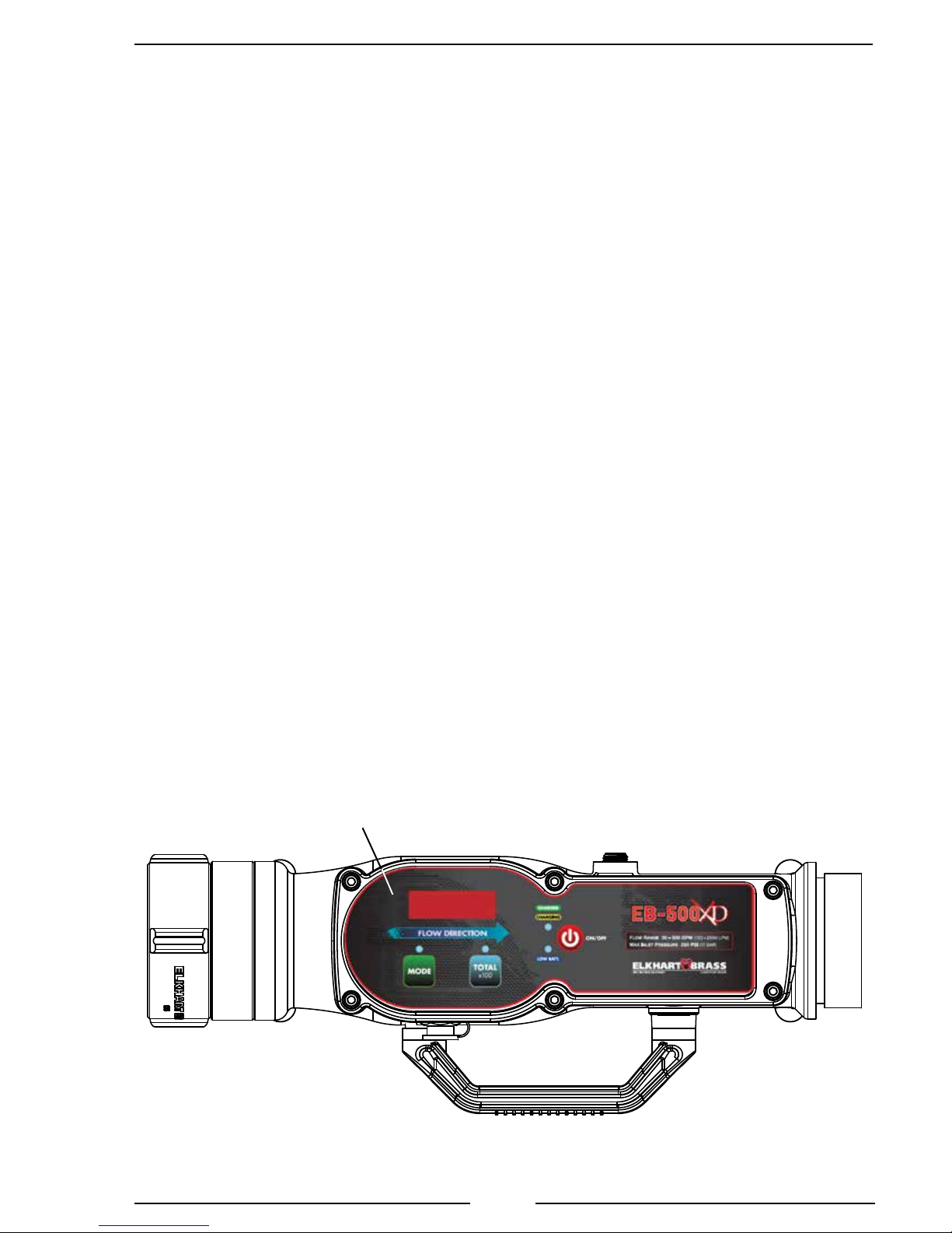
Figure 2. Controls and Indicators
Controls and Indicators
Refer to Figure 2 below for a diagram showing the pushbuttons and LED indicators
ontheowmeter.
ON/OFF Button
Pressandreleasethispushbuttontoturntheowmeteronoroff.
Display
Duringnormaloperationthe4-digitLEDdisplayindicatesowrate.Whenthe
displaymoduleidenticationorprogramaccessmodesareselected,modulespecic
information, program codes, and settings are displayed. (Refer to Programming Section
for more information.)
MODE Button
The MODEbuttonaccessestheidenticationmode.ItisusedwiththeTOTAL
button to input data when in the program access mode. (Refer to Programming Section
for more information.)
TOTAL Button
The TOTALbuttonallowstheoperatortodisplaytotalowforadischarge.When
the button is pressed, the value shown in the digital display, times 100, is the total
ow.ItisusedwiththeMODE button to input data when in the program access mode.
(Refer to Programming Section for more information.)
TOTAL x 100 LED
This green LED above the TOTAL button is on to indicate that the displayed value
times100equalsthetotalaccumulatedow.
Display

EB# 98601000 REV REL
10
Program Features
See Programming Section for more detailed information.
High and Low Flow Warning (Codes 315 and 316)
Whentheowrateisabovetheprogrammedhighowvalue,aashing-HI-is
showninthedigitaldisplay.Whentheowrateisbelowtheprogrammedlowow
value,aashing-LO-isshowninthedigitaldisplay.Thetypicalsettingis30-500GPM
(120-2000 LPM).
Flow Cutoff (Codes 318 or 319)
Thedigitaldisplayindicates0whentheowrateisbelowtheprogrammedow
cutoff value.
TOTAL Button
The TOTALbuttonperformstwofunctions,displaytotalowforadischargeor
resetthetotalizedowvalueto0(iftotalizerresetfunctionissettoYES).
Display Total Flow
When the TOTAL button is pressed and released the digital display shows the
totalaccumulatedowandtheTOTALx100 LED is on. (Multiply the value show in
the display by 100.)
Press and release the TOTALbuttonagaintoshowcurrentowrate.
Flowtotalisresetto0duringoperationsbydisplayingthetotalowandthen
pressing and holding the TOTAL button until the display shows 0.
Reset Total Flow to 0
Bydefault,TotalFlowisrestoredwhenpowerisappliedtotheowmeter.Also,
it can automatically reset to 0 upon power up. (Refer to Programming Section).

EB# 98601000 REV REL
11
PROGRAMMING
The program access mode is selected and inputs are made using the two pushbutton
switches on the front of the display module. The digital display shows stored data and
operator inputs. (Refer to Figure 1.)
Note: When entering codes in the program access mode there is a time-out
feature that requires an operator input every three seconds. If an input is
notdetectedwithinvesecondstheprogramreturnstonormaloperation.
Inputs
The two pushbutton switches on the front of the display module allows the operator
access to stored data and program functions.
Both the MODE and TOTAL buttons are used to enter program codes.
Once a program code is entered, the MODE button selects the digit to change and
the TOTAL button changes the digit or option choice.
Display Module Identication Mode
Wheninthemoduleidenticationmode,thedigitaldisplayshowsthemodule
serial number, manufactured date, software revision, function code, and ID number.
Themoduleidenticationmodeisadisplay-onlymodeandnochangescanbemade
to program information.
Note: There is a time-out feature that returns the program to normal operation
invesecondsifinputisnotdetected.
Select Display Module Identication Mode
Turn on power. Press and hold the MODE button, then press the TOTAL button
andreleaseboth.Theprogramentersthedisplaymoduleidenticationmodeandthe
display shows the module serial number. Press the MODE button a second time and
the display shows the manufacturing date. Each time the MODE button is pressed the
displayshowsthenextblockofstoredidenticationdata.
NOTE:Ifthebuttonisnotpressedforvesecondstheprogramrevertsto
normal operation.

EB# 98601000 REV REL
12
Program Access Mode
To gain access to the program features a three-digit program code must be entered.
Review the Program Code Descriptions or refer to Table 1. Program Code Quick
Reference for the proper three-digit code.
Note: There is a time-out feature that returns the program to normal operation
invesecondsifinputisnotdetected.
Select Program Access Mode
Turn on power. Press the MODE button and hold it until the display shows four
dashes. The program is ready for a three-digit program code to be entered.
Enter Program Code
Note: There is a time-out feature that returns the program to normal operation
invesecondsifinputisnotdetected.
1. Select the Program Access Mode (four dashes are shown in the display).
2. Press the MODEbutton.Thenumber100showsinthedisplaywiththerst
digit(1)ashing.EachtimetheMODE button is pressed the number increments
by1.Settherstdigittothedesirednumber.
3. Press the TOTALbutton.Theseconddigitashes.EachtimetheTOTAL button
is pressed the number increments by 1. Set the second digit to the desired number.
4. Press the MODEbutton.Thethirddigitashes.EachtimetheMODE button is
pressed the number increments by 1. Set the third digit to the desired number.
When a valid three-digit program code is entered, a program value or an option
shows in the display. If an invalid code is entered an error code shows in the display.
Note: When a valid code has been entered and a program value or an option
shows in the display, the time-out feature is disabled.
Change Values or Options
Press the MODEbuttontoselectthedigittobechange.Thedigitashes.Press
the TOTAL button to change the digit or the option choice.
Exit Program Access Mode
Press and hold the MODE button and then press the TOTAL button and hold them
until the display shows four dashes. Release the buttons and enter a new code, or after
vesecondstheprogramtimesoutandreturnstonormaloperation.

EB# 98601000 REV REL
13
CODE FEATURE OPTION
311 Flow Rate Increment Set Point 0000 to 9999
315 High Flow Warning 0001 to 9999
0 = Disabled
316 Low Flow Warning 0001 to 9999
0 = Disabled
317 Totalizer Reset Yes=Resetsto0atPowerOn
No = Stores Total Flow at Power Off
318* Flow Cutoff (Frequency) 0 to 99.9 Hz
319* Flow Cutoff (Flow Rate) 0 to 999
321 Flow Calibration (Single Point) 1 Calibration Point
322 Flow Calibration (Multiple Point) 9 Calibration Points
E202 Invalid Program Code Entered Re-Enter Code
E204 No Flow Sensor Signal Check Water Flow
E206 Invalid Calibration Point Select Different Calibration Point
E210 Exceeded Maximum Calibration
Points
Exit Calibration Procedure
Table 1. Program Code Quick Reference
Notes:
- Refer to Program Code Descriptions for detailed information.
- The time-out feature returns the program to normal operation in ve
seconds if input is not detected.
- When a valid code has been entered and a programed value or option is
shown in the display, the time-out feature is disabled.
* Code 318 is valid when the code 319 is set to 0. When a value is set for
code 319, code 318 is ignored.

EB# 98601000 REV REL
14
Program Code Descriptions
When a valid three-digit program code has been entered, a program value or option
shows in the display. The MODE and TOTAL buttons are used change the data.
Press the MODEbuttontoselectthedigittobechange.Thedigitashes.Press
the TOTAL button to change the digit or the option choice.
Code 311 Flow Rate Increment Set Point
Factory programmed value: 500 GPM
Options: 0000 to 9999
This code sets where the digital display changes from increments of 1 to increments
of10.Thedisplayvaluesincrementby1atowratesbelowthesetpointandby10at
owratesabovethesetpoint.Thiscodedoesnotimpactowwarnings,owcutoff
settings,orowratedisplaywheninthecalibrationprogram.
Code 315 High Flow Warning
Factory programmed value: Default – 500 GPM
Options: 0001 to 9999
This code sets the high ow warning. When the ow rate is above the high
ow warning programmed value, the ow display alternately ashes the ow rate
and -HI-.
Code 316 Low Flow Warning
Factory programmed value: Default – 30 GPM
Options: 0001 to 9999
Thiscodesetsthelowowwarning.Whentheowrateisbelowthelowow
warningprogrammedvalue,theowdisplayalternatelyashesbetweentheowrate
and -LO- .
Code 317 Totalizer Reset
Factory programmed value: NO
Options: YES,no
Thiscodetogglestheowtotalizerresetfunctiononandoff.Thetotalizerreset
functionhastwoprogramsettings;YESandno.Fortheresetfunctiontoworkthe
totalizerresetissettoYES.Flowtotalisresetandstartsfrom0whenpowerisapplied.
Flow total is reset to 0 when the TOTAL button is pressed and held. When the totalizer
resetissettono,theowtotalcontinuestoaccumulateanddoesnotresetto0even
when power is removed.

EB# 98601000 REV REL
15
Code 318 Flow Cutoff (Frequency)
Factory programmed value: 0
Options: 0 to 99.9 Hz
This code sets a cutoff frequency for the ow sensor. There is always some
turbulenceinthe pipethatcouldcausethe owsensor toturn whenthedischarge
isclosed.Thiscancausethedisplaytoshowaowratewhenthereisnoow.The
frequencycutoffissetsothatthedisplayshows0owwhentheowsensorsignalis
below the programmed value.
Note: Code 318 is valid when the code 319 is set to 0. When a value is set
for code 319, code 318 is ignored.
Code 319 Flow Cutoff (Flow Rate)
Factory programmed value: F 0
Options: 0 to 999
Thiscodesetsacutoffowratefortheowsensor.Thereisalwayssometurbulence
inthepipethatcouldcausetheowsensortoturnwhenthedischargeisclosed.This
cancausethedisplaytoshowaowratewhenthereisnoow.Theowratecutoff
issetsothattheowdisplayshows0owwhentheowsensorsignalisbelowthe
programmed value.
Code 321 Flow Calibration (Single Point)
Options: 1 Calibration Point
Thiscodestartsthecalibrationprogramforasingleowrate.
Refer to Calibration Section.
Code 322 Flow Calibration (Multiple Point)
Options: 9 Calibration Points
Thiscodestarts thecalibrationprogramformultiple owrates. Itcorrectsfor
nonlinearowtoprovideanaccurateowratedisplay.
Refer to Calibration Section.

EB# 98601000 REV REL
16
Error Code E202
An invalid program code has been entered. Re-enter the program code when the
digital display resets.
Error Code E204
There is no signal from the sensor. This code is displayed only when in a calibration
program.Troubleshootthesensorbyspinningitbyhandandthenconrmingifthe
displayshowsownumbervalues.
Error Code E206
A selected calibration point is too close to the previous point. (There is less than
5% difference between two calibration points.) Select a different point to continue with
the calibration procedure.
Error Code E210
The number of available calibration points have been exceeded. Exit the
calibration program.
Exit Program Access Mode
Press and hold the MODE button and then press the TOTAL button and hold them
until the display shows four dashes. Release the buttons and enter a new code, or after
vesecondstheprogramtimesoutandreturnstonormaloperation.

EB# 98601000 REV REL
17
CALIBRATION
Theowmeterisprecalibratedandtestedatthefactory.Itisrecommendedthat
theowmeterischeckedafterinstallationforaccuracyandcalibratedwhennecessary.
Review the Programming Section procedures for using the Program Access Mode.
Error Code E204
IferrorcodeE204isshown,thereisnosignalfromtheowsensor.Thiscodeis
displayed only when in a calibration program.
Note: To calibrate the owmeter, use a precalibrated water ow test kit
(connected to the discharge according to the instructions provided) or a
Pitot gauge as a reference.
Flow Calibration, Single Point (Code 321)
Selectaowrateforcalibrationthatiswithinthemostcommonlyuseddischarge
owrange.
1. Enter code 321.
Result:Thedigitaldisplayshowsowratewiththelastdigitashing.
2. Flow water through the discharge at the ow rate selected for calibration.
Ensureaconstantpressureismaintainedtoobtainasteadyowrate.
3. Adjustthedisplayedowratetomatchthereferenceowrate.
The MODEbuttonselectsthedigittochange.Thedigitwillash.
The TOTALbuttonchangesthevalueoftheashingdigit.
4. To exit the calibration program:
Press and hold the MODE button and then press the TOTAL button and hold them
until the display shows four dashes. Release the buttons and enter a new code, or
aftervesecondstheprogramtimesoutandreturnstonormaloperation.
5. Varythewaterowthroughthedischargeandensuretheowratedisplayed
matchesthereference.Iftherearedifferencesatotherowrates,themultiple
point calibration may be necessary.

EB# 98601000 REV REL
18
Flow Calibration, Multiple Point (Code 322)
Thisfunction isused when theow sensor isinstalledin adifcultplumbing
locationwhereowisnotlinear.Itcorrectsfornonlinearowtoprovideanaccurate
owratedisplay.
Select calibration points (up to 9) that are within the most commonly used range.
Note: There must be at least a 5% difference between each calibration point.
If a selected calibration point is too close to the previous point, an E206
error code shows on the display.
1. Enter code 322.
Result: The digital display shows Pt1 (program is ready to set the rst
calibration point).
2. Flowwaterthroughthedischargeattheowrateselectedforthecalibration
point.Ensureaconstantpressureismaintainedtoobtainasteadyowrate.
3. Press the MODE button.
Result:Thedisplayshowsowratewiththelastdigitashing.
4. Adjustthedisplayedowratetomatchthereferenceowrate.
The MODEbuttonselectsthedigittochange.Thedigitwillash.
The TOTALbuttonchangesthevalueoftheashingdigit.
5. Press and hold the MODE button, momentarily press the TOTAL button, release
the buttons. The next calibration point is displayed. (If the buttons are pressed
too long, the program exits the calibration mode.)
Result: The display shows Pt2 (or the next calibration point).
6. Repeatsteps2through5foreachowratetobecalibrated.
7. To exit the calibration program:
Press and hold the MODE button and then press the TOTAL button and hold them
until the display shows four dashes. Release the buttons and enter a new code, or
aftervesecondstheprogramtimesoutandreturnstonormaloperation.

EB# 98601000 REV REL
19
FLOWMETER CHARGING
Thefollowingguresincludewiringandcableinformation.
2-Pin Connector/Cable
Pin Description
1 Power
2 Ground
Figure 3. Charging
Charging Port
(12/24 VDC) Vent
Pin 1 Pin 2
AC to DC Switching Adapter
Input: 100-240 VAC
50-60 Hz
0.7A
Output: 15V
2A
Status: Blue LED on the power adapter indicates
power is available.

EB# 98601000 REV REL
20
Table of contents
Other ELKHART BRASS Measuring Instrument manuals


Popular Measuring Instrument manuals by other brands


Wintriss
Wintriss AutoSet PAC 120 VAC user manual

HT Instruments
HT Instruments SOLAR03 user manual

PCB Piezotronics
PCB Piezotronics IMI Sensors TO625B01 Installation and operating manual

Hinds Instruments
Hinds Instruments EXICOR 150AT user manual

LORD
LORD 3DM -CV5-10 user manual

Danmeter
Danmeter CSM Refill Manual

CHAMELEON
CHAMELEON IHD6-CAD-PPMID manual

Siemens
Siemens AlgoRex DJ1191-Ex installation instructions

Assured Automation
Assured Automation WM-NLD Series Installation, operation & maintenance manual

PCME
PCME QAL 181 X user manual

MARTINDALE
MARTINDALE PSI4000 instruction manual

Signal Hound
Signal Hound BB60D product manual