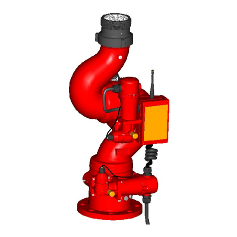
ELKHART BRASS Cobra Max 81910 Assembly instructions

98634000, Rev REL
TM
Installation, Operating, & Maintenance Instructions
1-574-295-8330
www.elkhartbrass.com

2
Contents
CobraMax™Kit – 81910................................................................................2
CobraMax Installation ................................................................................4
CobraMax Parts Drawing .............................................................................10
CobraMax Parts List ..................................................................................11
Changing Light Module Colors .........................................................................12
Wi-Fi Mode Indication ................................................................................12
Custom Etched Lenses (Side Light Modules) ............................................................12
CobraMax™Kit – 81910
The CobraMax is a combination shroud cover and lighting kit that gives a sleek and
sophisticated look to the Cobra EXM2 monitor.The attractive thermoformed shroud cover is
not only visually appealing, but also hides and adds a layer of protection over much of the
otherwise exposed wiring typical of the standard Cobra EXM2 monitor.The lighting modules
of the CobraMax Kit can be changed to a number of in-field selectable colors to fit a particular
installation or occasion.The Back Light Module displays the CobraMax Logo while the Side
Light Modules display the Elkhart Brass Elk and Heart logo (standard).The optional Custom-
Etched Side Lenses allow customers to personalize the look of the Side light modules with
their own logo such as a department emblem, station number, or other desired image. With
the superior aesthetic of the CobraMax Kit the Cobra EXM2 monitor becomes a focal point of
any installation.
The CobraMax shroud covers come in a choice of Matte Black, Gloss Black, Gloss Red, or
Gloss Gray.The lighting modules can be user-set to a range of colors including Blue, Green,
Yellow, Red, and White.
The CobraMax Kit is compatible with any combination of Cobra monitor version that has
received the CobraMax-Ready mounting bosses (Any monitor sold after 11/1/2019 should
include these bosses). CobraMax compatible combinations include both 7200 and 7250
designations, both SD or HD motor options, both ¾" Nut or Handwheel Overrides, any
currently available base option, and both NHT or BSPP discharge thread options.

3
CobraMax-Ready
Mounting Bosses
Side Light
Modules
Back Light
Module
Shroud Cover

4
CobraMax Installation
Reference the CobraMax Kit Parts Drawing on Pages 10-11 for more detail on parts used.
1. Position the monitor so that the discharge is pointed straight up away from its base
as shown. Power off the monitor and disconnect its main power harness. Collect the
following tools that will be required to perform the CobraMax installation.
2. Remove the spring pins and either the override nuts or handwheels from the Cobra
Assembly. Save these parts in a place where they will not be lost or damaged, they
will be used again later. Use Channellock pliers to attach the CobraMax override shaft
extensions with the provided 1/8" diameter, 5/8" long spring pins. Further secure the
override shaft extensions in place by installing the provided #10-32 set screws into the
override shaft extensions. Apply blue Loctite #243 or an equivalent thread locker to the
screw threads.
Tools Required for Assembly:
•1/8" Diameter punch
•Hammer
•Channellock Pliers
•1/8" Allen or T-Handle Wrench
•9/64" Allen or T-Handle Wrench
•Torque Wrench or Screwdriver w/ #2 Phillips
•3/8" or Adjustable Wrench
•Loctite #243, or equivalents
•O-Ring Compatible Grease
¾" Nut Override Removal Handwheel Override
Removal
Attach Override Extensions
and Set Screws

5
3. Remove the EXM2 Module by removing the four #8-32 screws holding it in place.
Disconnect the Green Deutsch connector and remove its wedge lock. Remove the pin
plugs from the appropriate holes and insert the wires of harnesses 37573000 as shown
here. Reinsert the wedge lock into the Deutsch connector and connect it back to the
EXM2 module. Reattach the EXM2 module with the same four #8-32 screws. Route the
wires down through the cutout in the inlet body with the main power harness. Apply blue
Loctite #243 or an equivalent thread locker to the screw threads.
4. Install the provided standoffs and spacers onto the monitor body in the four locations
shown. Install the upper brackets and spacers onto the monitor body using the provided
flat head screws as shown. Apply blue Loctite #243 or an equivalent thread locker to the
flat head screws. Apply red Loctite #272 or an equivalent thread locker to the standoffs.
EXM2 Module Removal
Attach Standoffs
and Spacers
Attach Upper Brackets
and Spacers
Green Deutsch
Connector
Wedge Lock
WIRE COLOR PIN LOCATION FUNCTION
RED 1 POWER
BLACK 11 GROUND
YELLOW 3 CAN LOW
GREEN 10 CAN HIGH
1 2 3 4 5 6
12 11 10 9 8 7
INSERT LEADS FROM HARNESS 37573000
INTOTHE GREEN 12 PIN CONNECTOR ON HARNESS
37081000 AS SHOWN IN THETABLE
HARNESS 37573000
GREEN 12 PIN DEUTSCH
CONNECTOR, PN 24192000

6
5. Attach two Light Module Support brackets onto the back half of the monitor shroud with
four of the provided Socket Head #8-32 screws as shown. Attach the Back Light Module
to the back half of the shroud with the four Pan Head #8-32 screws provided (Insert the
Light Module wires through the cutout in the shroud). Orient the Back Light Module as
shown. Apply blue Loctite #243 or an equivalent thread locker onto the female threaded
holes of the brackets before assembling.
6. Connect the Back Light Module to the EXM2 Module using the appropriate Deutsch
connector. Attach the Back Shroud to the monitor using six of the #10-32 Pan Head
screws provided. Apply blue Loctite #243 or equivalent thread locker onto the female
threaded holes of the brackets and standoffs before assembling.
Attach Light Module Support
Brackets
Connect Module Wires
Attach Back Light Module
Attach Back Shroud

7
7. Attach the Front Shroud onto the monitor as shown with six of the #10-32 Pan Head
Screws provided. Insert the nozzle wire harness through the shroud and install the
rubber grommet in the hole as shown. Attach four of the Light Module Support Brackets
into the locations shown using the provided #8-32 screws. Apply blue Loctite #243 or
equivalent thread locker onto all the female threaded holes in the various brackets and
standoffs before assembling.
8. Connect the Left and Right Light Module cables to the respective cables coming from
the Back Light Module as shown. Mount the Left and Right Light Modules to the Shroud
Covers as shown with the provided #8-32 Socket Head Screws (Tuck the Side Light
Module wires inside the Shroud Assembly). Blue Loctite #243 or an equivalent thread
locker should be applied to the female threaded holes of the brackets.
Attach Front Shroud
Connect Side Light Module Cables
(A Portion of the Back Shroud is Hidden inThis View)
Attach Side Light Modules
Attach Light Module Brackets
(A Portion of the Front Shroud is Hidden inThisView)

8
9. Apply a generous amount of Mobilux EP2 Lithium Grease or an appropriate O-ring
compatible grease to the provided AS-568-048 and AS-568-049 O-Rings. Install the
AS-568-049 O-Ring onto the Right and Left Light Module housings as shown. Install the
AS-568-048 O-Rings into the Light Module Bezels as shown.
(Reference: The -049 O-ring is larger than the -048 O-Ring)
10. Install the Side Light Module lenses into the Bezels as shown. Then attach the Bezels
and Lenses to the Side Light modules with the provided #6-32 Pan Head screws. Apply
blue Loctite #243 or an equivalent thread locker to all screw threads. Torque the screws
to 10 In-Lbs. The Lenses should be installed so that the coated surface is on the inside of
the Light Module assembly and the image is displayed correctly.
AS-568-048 O-Ring
In Light Module Bezel
AS-568-049 O-Ring
In Light Module Housing
Install Lenses into Bezels Attach Bezels with Lenses to
Light Modules

9
11. Use Channellock pliers to attach the override ¾" Nut or Handwheels removed previously
to the override extensions. Use the same spring pins that were removed previously to
hold them in place.
12. Reconnect the main power harness to the monitor and power on the monitor. Rotate the
monitor and ensure that the monitor does not contact the shroud covers in a way that
will cause damage to the shroud covers. View the three Light modules and ensure that
they light up as intended.
Attach ¾" Nut Overrides
Completed CobraMax Assembly
Attach Handwheel Overrides

10
CobraMax Parts Drawing
17
25
15
12
2
3
15
22
19
21
1
14 13
20
23
15 62 15
12
4
26
12
11
9
16
5
10
22
19
8
18
7
27
COBRAMAX KIT PARTS DRAWING

11
CobraMax Parts List
COBRAMAX KIT PARTS LIST
SHROUD COLOR OPTIONS
SIDE MODULE LENS OPTIONS
PART
NUMBER DESCRIPTION
24731000 SHROUD BACK - MATTE BLACK
24733000 SHROUD FRONT - MATTE BLACK
24731001 SHROUD BACK - RED
24733001 SHROUD FRONT - RED
24731002 SHROUD BACK - GLOSS BLACK
24733002 SHROUD FRONT - GLOSS BLACK
24731003 SHROUD BACK - GRAY
24733003 SHROUD FRONT - GRAY
PART
NUMBER DESCRIPTION
52875001 LENS - DEFAULT 'ELK & HEART' LOGO
52875002 LENS - CUSTOMER SUPPLIED ARTWORK
ITEM
NO. PART
NUMBER DESCRIPTION
1 18559001 BRACKET - COBRAMAX UPPER SUPPORT 2
2 18582001 BRACKET - CMAX LIGHT SUPPORT 6
3 2473100X COVER - 7200/7250 SHROUD (BACK) 1
4 2473300X COVER - 7200/7250 SHROUD (FRONT) 1
5 28509000 ENCLOSURE - CMAX (SIDES) BEZEL 2
6 33759000 GROMMET - 7/8HOLE 1/8PANEL 3/4ID 1
7 37573000 HARNESS - CMAX LIGHT 1
8 51248000 PIN ROLL 79-028-125-0.625 2
9 5287500X LENS - SIDE MODULE (ETCHED) 2
10 57552000 O-RING AS-568-048 2
11 59231000 O-RING AS-568-049 2
12 64103000 SCREW 8-32X0.500 SOC CAP SS 20
13 64334000 SCREW-#10-32X0.750 LFT HD ALLEN 5
14 64335000 SCREW-#10-32X0.750 FLT HD ALLEN 1
15 64336000 SCREW-#10-32X0.375PAN PHILLIPS 12
16 64337000 SCREW-#6-32X0.312 PAN HD PHILLIPS 20
17 65164000 SCREW - 8-32 X 0.750 PAN HD 4
18 65233000 10-32 x 0.125 SOC SET SCREW FL PT SS 2
19 65634000 SPACER - #10SCR 1/2 ODX0.188TALL 4
20 65635000 SPACER - #10SCR 1/2 ODX0.250TALL 5
21 65636000 SPACER - #10SCR 1/2 ODX1.125TALL 1
22 65637000 STANDOFF - #10-32 X 0.375 TALL 4
23 67559001 SHAFT - CMAX OVERRIDE EXTENSION 2
24 81915000 LIGHT MODULE - CMAX BACK 1
25 81916000 Light Module - CobraMax (Right) 1
26 81917000 Light Module - CobraMax (Left) 1

12
Changing Light Module Colors
1. On any connected EXM2 input device, press and hold AUX + OSC. All three light
modules will begin flashing approximately 1 time every second.
2. Press either AUX or OSC to cycle between colors. Color choices are Blue, Green, Yellow,
Red, and White.
3. Once the desired color is displayed, wait 10 seconds.
4. When the light modules stop flashing, the color is set.
Wi-Fi Mode Indication
When the CobraMax shroud and lighting assembly has been assembled to a Cobra EXM2
monitor and the monitor Wi-Fi is turned on, the CobraMax light modules will turn blue and
begin flashing in an alternating (Back, Sides, Back, Sides) pattern to signal that Wi-Fi is on.
This light operation will continue until the Cobra EXM2 monitor turns off Wi-Fi. Once Wi-Fi is
turned off, the CobraMax light modules will stop flashing and will return to whatever color
they were previously set to.
Custom Etched Lenses (Side Light Modules)
The Custom Lens option for the CobraMax shroud and lighting assembly provides
customers the ability to display a chosen text, number, or image on their CobraMax
monitor assembly.This custom artwork will be displayed and illuminated on both of the
two Side Light Modules of the CobraMax assembly. Upon ordering custom CobraMax
Lenses and providing artwork meeting the requirements, the customer will be provided all
the parts needed to replace the standard ‘Elk & Heart’ lenses received as standard with
their CobraMax assembly with their chosen design.The Side Lighting Modules of the
CobraMax have been designed to allow customers to easily switch out the lenses in order
to display their created image.To purchase custom CobraMax lenses, contact an Elkhart
Brass representative at (574) 295-8330 and complete the CobraMax Custom Lens Order
Form which can be obtained at www.elkhartbrass.com.
Standard ‘Elk & Heart’ Lens Custom Etched Lens

13
CobraMax Specications –
• Shroud Cover Material –
■Matte Black: UV Resistant Acrylic Capped ABS
■Gloss Black, Gloss Red, Gloss Gray: UV Resistant Paint Film Covered ABS
• Light Module Enclosure Material – Glass Filled Nylon
• Additional Weight: 4 Lbs Approx.
• Swing Radius – 7.5" (190.5 mm)
• Seal Rating (Light Modules): NEMA 4
FCC Statement:
Note:This equipment has been tested and found to comply with the limits for a Class A digital device,
pursuant to part 15 of the FCC Rules.
These limits are designed to provide reasonable protection against harmful interference when the
equipment is operated in a commercial environment.
This equipment generates, uses and can radiate radio frequency energy and, if not installed and used
in accordance with the instruction manual, may cause harmful interference to radio communications.
Operation of this equipment in a residential area is likely to cause harmful interference in which case the
user will be required to correct the interference at his own expense.
Modifications made to this equipment not expressly approved by Elkhart Brass Mfg. Co., Inc., could void
the users authority to operate the equipment.
Innovation, Science and Economic Development Canada (ISED) Statements:
RSS-Gen and RSS-210 statement:
This device complies with Industry Canada license-exempt RSS standard(s), Operation is subject to the
following two conditions: (1) this device may not cause interference, and (2) this device must accept any
interference, including interference that may cause undesired operation of the device.
Le present appareil est conforme aux CNR d'lndustrie Canada applicables aux appareils radio exempts
de licence. L‘exploitation est autorlsée aux deux conditions suivantes : (1) l'appareil ne doit pas produire
de brouiliage, et (2) l'utilisateur de l’appareil doit accepter tout brouiliage radioélectrique subi, meme si le
brouiliage est susceptible d'en compromettre le fonctionnement.
CE Statements:
Elkhart Brass declares the product conforms to Machinery Directive 2006/42/EC. In addition to the above
mentioned directive, the products conform to the following European Directives:
Electromagnetic Compatibility Directive 2014/30/EU
Pressure Equipment Directive 2014/68/EU
Low Voltage Directive 2014/35/EU
The following harmonized standards and specifications are applied:
EN ISO 12100:2010 Safety of Machinery
See our website at www.elkhartbrass.com for more information.
RF Immunity for CE
When subjected to strong RF radiation, the light panel may experience intermittent color changes that will
resolve when Strong RF field is removed.This behavior is expected and normal, and will not cause any
lasting damage to the device.

14
NOTES

15
NOTES

Elkhart Brass Manufacturing Co., Inc.
1302 W. Beardsley Avenue Elkhart, IN 46514
Tel. (574) 295-8330
Toll Free (800) 346-0250
Fax (574) 293-9914
www.elkhartbrass.com
Email: eb.info@safefleet.net
98634000, Rev REL
05-21
Table of contents
Other ELKHART BRASS Measuring Instrument manuals
Popular Measuring Instrument manuals by other brands
Hamron
Hamron 619-566 User instructions
Niigata seiki
Niigata seiki QEM394 Series instruction manual
doble
doble M4000 series user guide
ProMinent
ProMinent DULCO flex Control operating instructions

Fuji Electric
Fuji Electric ZPAJ instruction manual
Wildlife Acoustics
Wildlife Acoustics SMART MIC-1 user guide
