ELKHART BRASS Spit-Fire 08394159 Guide

08394159 Monitor
Installation, Operation, & Maintenance Instructions For
ATEX Applications
1302 WEST BEARDSLEY AVE •ELKHART, IN 46514 •574-295-8330 •800-346-0250 98370000 REV D

3
PRODUCT SAFETY INFORMATION
•Whenever possible, this equipment should be operated from a remote location to avoid
exposing personnel to dangerous fire conditions.
•Drain all water from monitor after each use or freeze damage may occur.
•
All personnel who may be expected to operate this equipment must be thoroughly trained in its safe
and proper use.
•
Before flowing water from this device, ensure that all personnel (fire service and civilian) are clear of
thestreampath. Confirmstreamdirectionwillnotcauseavoidablepropertydamage.
•
Become thoroughly familiar with the hydraulic characteristics of this equipment, as well as the
pumping system used to supply it.
•Water valve’s that are provided by Elkhart Brass are programmed to close slowly to avoid
water hammer. Always open and close valves slowly to avoid water hammer.
•
After each use, and on a scheduled basis, inspect equipment per instructions in the maintenance
section.
•Keep fingers and hands clear of moving parts.
•
Disconnect power before servicing the motors, electric valve, or electric valve controller.
•
Any modifications to the electrical motors will destroy the IP-66 rating and void warranty
coverage of the
enclosure and all components within.
•
All equipment must be installed in accordance with ATEX requirements (EN/IEC 60079-14) as
appropriate and in areas where equipment classification is suitable.
MONITOR INFORMATION:
SERIAL NUMBERS:
DETAILS:
Important:
Before installing and operating this equipment, read this manual
thoroughly. Proper installation is essential to safe operation.
Warning:
Do not attempt to disconnect or work on any electrical equipment in this
system unless power is removed, or the area is known to be non-hazardous.

4
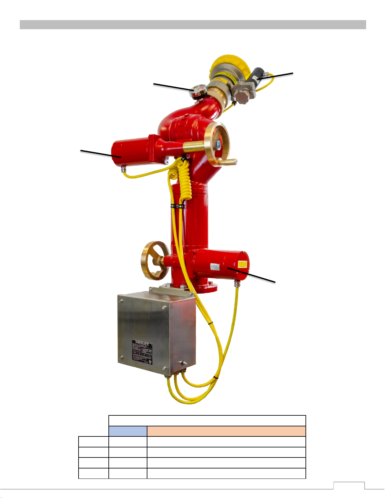
MONITOR CALLOUT
Figure 1: Monitor Callout Drawing
Pressure Gauge
Vertical Manual
Override
Double Race Bearings
Junction Box
Constant
Torque/Constant
Current Motor
4”-150# ANSI Flange
Nozzle Manual
Override
Horizontal Manual
Override

5
OVERVIEW
ATEX S
pi
t
-
Fire
Mon
itor
F
e
atu
res:
•Construction: All brass with vaned 4” waterway
•Mounting Flange: 4” 150# flat-face ANSI flange (raised face flange available as option)
•Discharge: 3½” NHT male outlet
•Stream Shaper: #284-B brass shaper included
•Flow: 2000 GPM, 200 PSI (7570 LPM,14 BAR) max working pressure
(with optional SM-2000BE-HL nozzle)
•Monitor:
oATEXCertifiedto:
CE2776 Ex II 2 GD
Ex db eb h IIC T4 Gb
Ex h tb IIIC T130°C Db
IP66
•Motor:
o240 VAC synchronous motors (non-arcing)
oConstant torque and current draw in start, running, and stall
oMotors are capable of sustained, continuous oscillation.
oInstantaneous start, stop, and reverse
oResidual (Power Off) torque is always present
oLong life and exceptional reliability
o240 VAC, 50/60 Hz., 1 Phase, 0.40 Amp current per motor
oClass I, Div. 2. Groups A, B, C, & D, T4
•Junction Box:
CE
0539
Ex II 2 G Ex e IIC T4 Gb
-50°C ≤ Ta ≤ 70°C
CE0539
Ex II 2 D Ex tb IIIC T120°C Db IP66
DEMKO 01 ATEX 130438X
IECEx UL 09.0017X
•Range of Motion: Monitorstops arefactorysetat 346° horizontal(+173°to -173° fromfront
center), and 135° vertical (+90° to -45°)
•
Rate of Horizontal Motion: 0.116 °/second at 50 Hz.
•Manual Override:
Hand wheels provided for vertical, horizontal, and nozzle movements.
Hand wheel
will not rotate when monitor is operated electrically.
Warning: DO NOT TAKE COVER OFF OR DISASSEMBLE MONITOR MOTORS. If
cover is/has been removed, the warranty is void and the service life of the motor is
significantly reduced. Disassembling the motor will ruin the waterproof characteristics
of the motor.
6
INSTALLATION INSTRUCTIONS
Monitor Installation
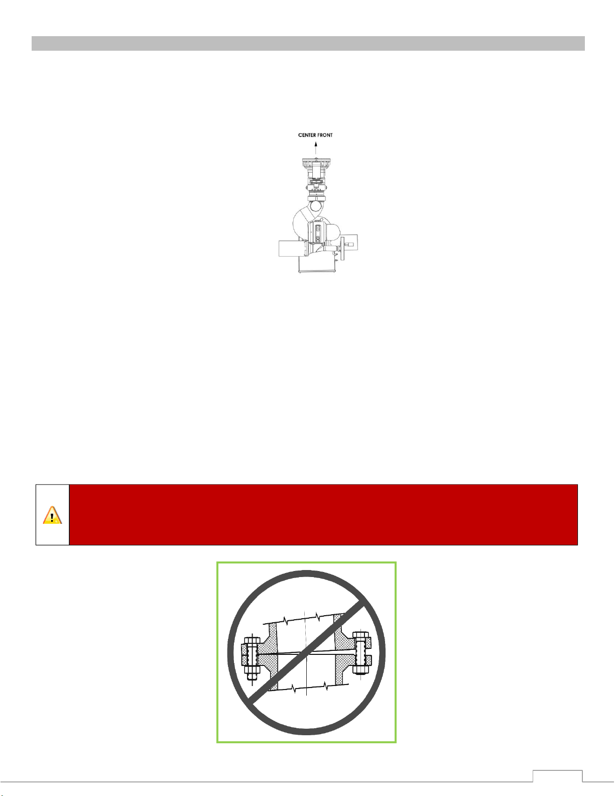
1.
Attach companion flange to water supply pipe so that the bolt pattern will allow the monitor to be
installed with the “CENTER FRONT”position (shown below) properly
aligned. Alignment is
correct when the motors are oriented to match the illustration below with the hand wheels for
the horizontal and vertical motor are facing 180° from each other
2.
Installthemonitorassemblyonthewatersupplyflangesothatitmatchesuptoa4”-150#flat
faced ANSI flange on the inlet of the monitor, with a flange gasket between the flanges. Install
motor cable junction box by aligning the two-holed bracket with the flange mounting holes on the
rear of the monitor. Secure the inlet flange with eight (8) 5/8”-11 UNC Grade 5 hex head bolts.
Torque bolts to 60-70 ft-lbs. if using Elkhart Brass supplied gaskets. If using a gasket
supplied by others, follow manufacture’s guidelines.
3.
Standpipe must bestructurally strong enough to withstand reaction forcesofthenozzle when
discharging a straight stream at 90° of the standpipe tower. The formula for calculating nozzle
reaction is: [REACTION FORCE
=
0.0505 x GPM x √PSI]
4.
The inlet pressure at the base of the monitor must be high enough to allow for pressure loss
through the monitor. To accomplish this, use the pressure loss for GPM flowing and add to nozzle
pressure. See Monitor Hydraulic Data section for pressure loss chart.
Warning:
When installing the monitor on a raised face companion flange orwafer
type valve, it is critical that the bolts be tightened uniformly to prevent misalignment
of the monitor relative to the flange or valve. If the monitor becomes misaligned, the
base flange will fracture and fail when the bolts on the “high” side are tightened.

7
OPERATING INSTRUCTIONS
One Monitor Control
The Monitor Control Panel (MCP) has one set of switches and pilot lights to operate one monitor.
•Monitor Functions –UP, DOWN, LEFT, RIGHT, STREAM, and FOG are operated with spring
return knob lever switches. This is
accomplished by using the proper selector to move the
monitor the direction
desired. When the switch is released, it will return to the neutral (off)
position, and monitor movement
will stop.
Monitor Manual Control
•Vertical Manual Override –Push hand wheel inward toengageoverride. While holding
the
hand wheel in, rotating it clockwise will raise the nozzle, and rotating it counterclockwise
will
lower the nozzle.
•
Horizontal Manual Override –Push hand wheel inward to engage override. While holding
hand wheel in, rotating it clockwise will move the monitor right, and rotating it
counterclockwise will
move the monitor left.
•
Valve Manual Override –The manual hand wheel will turn whenever the actuator is
electrically operated. Do not attempt to operate the manual override handwheel if the
actuator is in operation. Turning the manual override wheel on an Elkhart Brass supplied
actuator clockwise closes the valve and turning the manual override wheel
counterclockwise will open the valve.
MAINTENANCE
After every use Inspection & Maintenance
When monitor operation is completed, move vertical movement to full down position to allow water to
drain from nozzle. After water is drained from thenozzle, move monitor to the “park”position, so
it is prepared for fighting a fire.
Monthly Inspection & Maintenance
•
Cycle all monitor functions (UP, DOWN, LEFT, RIGHT, STRAIGHT, FOG) to ensure the
complete system is fully
functional.
Six-Month Inspection & Maintenance
•Grease fittings are provided for the up-down and left-right rotation joints, routine greasing should be
performed to expel water & other contaminants that can get into the rotation joints. If the monitor is
exposed to a high level of radiant heat for a prolonged period, it may be possible for the factory
grease to thin and run out of the rotation joints. In such an event, fresh grease should be applied.
Use Mobilith SHC-100 or equivalent. Start at one end of travel range and apply grease through the
fitting of each joint until fresh grease comes out the joint. Repeat every 30 degrees throughout the
full range of travel on each rotation joint. Wipe off any expelled grease when done.
•Fill monitor with grease until full.
•Check motor control cables for damage.
•Check all painted surfaces for chips or scratches and repaint as required. Motors are coated
with a black waterproofing coating. Paint should be applied any time the black coating is
visible.
•Visually check all electrical equipment.
Warning:
Do not attempt to disconnect or work on any electrical equipment in this
system unless power is removed, or the area is known to be non-hazardous.

8
SPECIFICATIONS
General Specs
•
Input Power
240 VAC (50/60Hz.) 1 Phase
•
Electrical Load
0.40 AMPS Per Motor
•
Monitor Dimensions
23” dia. x 52”h
•
Monitor Weight Approx. 300 lbs.
MONITOR HYDRAULIC DATA
Figure 4: Monitor Friction Loss Chart
Pressure Drop (PSI)
9
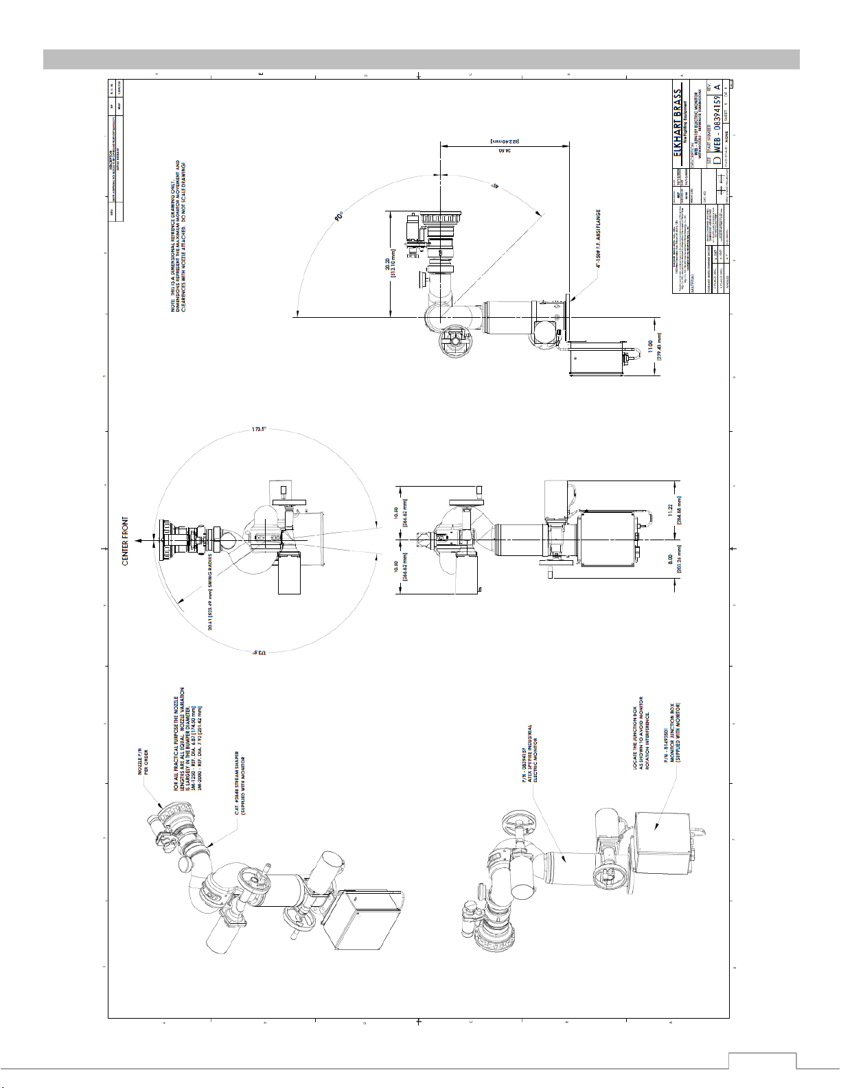
DIMENSIONAL DRAWING
Figure 5: Monitor Dimensional Drawing

10
WIRING
Figure 6: Monitor Cable Wiring to Junction Box Terminals
11
SPARE PARTS
ATEX SPITFIRE MODEL # 8394159
PART NO.
DESCRIPTION
A
460910SP1
MOTOR AND CABLE-ELECTRIC (240VAC) NOZZLE
B
46092SP1
MOTOR AND CABLE-ELECTRIC (240VAC) VERTICAL
C
460921SP1
MOTOR AND CABLE-ELECTRIC (240VAC) HORIZONTAL
D
33587000
PRESSURE GAUGE (0-300 PSI)
A
B
C
D

12
NOTES

Table of contents
Other ELKHART BRASS Measuring Instrument manuals


