Elko iNELS Air AirSD-100L User manual

1 / 4
AirSD-100L
02-62/2019 Rev.: 0
1
1
1
8
44
44
7
2
2
2
2
6
5
3
3
3
12
+
-
+
-
+
-
+
-
5
4
a)
b)
3
ON
1 2 3
+
-
-
+
-
+
-
ELKO EP, s.r.o.
Palackého 493
769 01 Holešov, Všetuly
Czech Republic
Tel.: +420 573 514 211
e-mail: [email protected]
www.elkoep.com
EN
Made in Czech Republic
Characteristics General instrucions
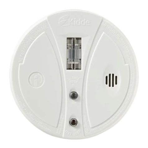
• The smoke detector is used for the early warning of an emerging re in residential
and commercial buildings and also measures the actual temperature, humidity
and light intensity in the room.
• The detector utilises a scanning method using an optical chamber, which has en-
hanced smoke detection responses.
• Self-test function highlights the failure of the detector, eliminating the malfunc-
tion in the event of a re.
• Anti-sabotage: If access to the device is unauthorized, a message is immediately
sent to the server.
• Thanks to the wireless solution and LoRa communication, it can communicate
instantly to your chosen location and be operated immediately.
• Data is sent to the server from which it can be subsequently displayed as a smart-
phone, application, or Cloud notication.
• Battery power can be sent to the server when it is powered by a battery.
• Power supply: battery 4 x 1.5 V AA, the battery life is around 1 year.
Description
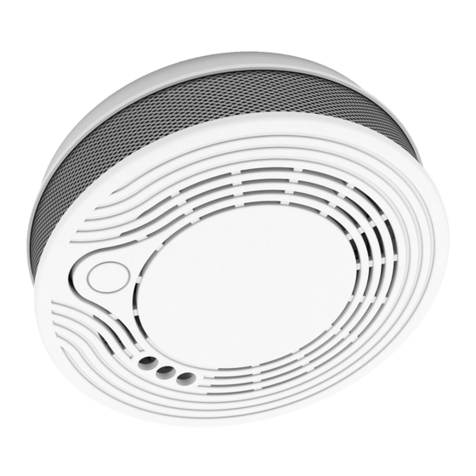
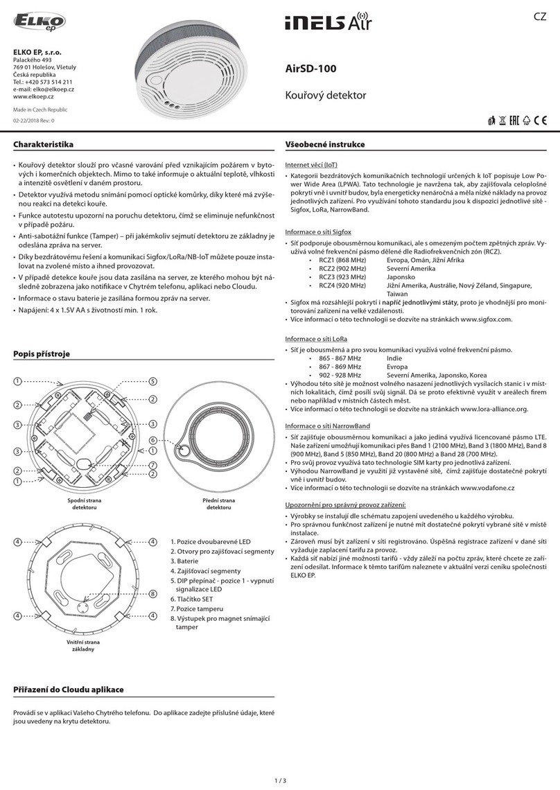
1. Two-color LED position
2. Holes for locking segments
3. Battery
4. Secure segments
5. DIP switch - Position 1 - Turn o
scanning signaling
6. Button SET
7. Ta mper p ositi on
8. Probe for magnet scanning
tampermenty
The underside of
the detector
The inner side of
the base
The front of the
detector
Cloud app assignment
It is done in your Smartphone application. Enter the relevant data located on the detec-
tor cover into the application.
Smoke detector
Assembly
1. Place the base at the desired location (on a at surface). You can use the base as a drilling
template. Attach the base with suitable bonding material * according to the substrate.
2. Insert the batteries into the detector and check that they are correctly positioned (a
detector functionality message will be sent to the application when the batteries are
inserted).
3. Set DIP 1 as required.
4. Attach the detector to the base so that the projection on the base faces the tamper posi-
tion in the detector cover (a). Turn the detector clockwise (b).
5. Press the test button to test the correct alarm function (see Test Detector Test).
* Suitable tting material can be, for example, a countersunk head screw, a screw Ø of
3 mm.
Internet of Things (IoT)
• The IOT wireless communications category describes the Low Power Wide Area
(LPWA). This technology is designed to provide full-range coverage both inside and
outside buildings, energy-saving and low-cost operation of individual devices. The
LoRa network is available to use this standard.
LoRa network information
• The network is bidirectional and its communication uses free frequency band.
• 865 - 867 MHz India
• 867 - 869 MHz Europe
• 902 - 928 MHz North America, Japan, Korea
• The advantage of this network is the possibility of freely deploying individual stations
in local locations, thus strengthening their signal. It can therefore be used eciently in
company premises or, for example, in local parts of cities.
• For more information on this technology, please visit www.lora-alliance.org.
Caution for proper operation:
• Products are installed according to the wiring diagram given for each product.
• For proper device functionality, it is necessary to have sucient coverage of the selec-
ted network at the installation site.
• At the same time, the device must be registered in the network. Successful device re-
gistration on a given network requires a charge for trac.
• Each network oers dierent tari options - it always depends on the number of me-
ssages you want to send from your device. Information on these taris can be found in
the current version of the ELKO EP pricelist.

2 / 4
min. 30 cm
min. 15 cm
max. 30 cm
min. 150 cm
min. 30 cm
AirSD-100
AirSD-100AirSD-100
min. 15 cm
min. 50 cm - max. 600 cm
AirSD-100
AirSD-100
b)
a)
Function
An internal, battery-powered smoke detector combines the timely detection of smoul-
dering and open res from which smoke escapes. It is equipped with an optical smoke
detector for smoke detection. An example of a smouldering re is a burning cigarette on
a couch or bedding, which is a common cause of res.
Indicators and detector states
After inserting the batteries, the detector sends an introductory message containing the
measured temperature, humidity, light intensity, optical-smoke sensor status, and rm-
ware version of the device.
• The detector scans for smoke every 10 seconds, the green LED blinks at the same time
(the LED signalling can be switched o by the DIP switch). Every 10 minutes the detec-
tor senses temperature, humidity and light intensity. Displays the measured data re-
port at six hourly intervals. In the case of smoke detection or rapid temperature change
it is displayed immediately.
• Alarm - the sensor detects smoke, the red LED blinks within 1 second, the detector
emits a loud, intermittent „beep“. Terminate the alarm by scattering the smoke. The
audible alarm can be switched o by the test button, in the case of positive smoke
detection; the audible alarm is restored after 5 minutes.
• Dead battery:
- sending a message to the server
- every 5 s 3 times the red LED lights up on the detector.
• Detector failure:
- sending a message to the server
- Indication of the red LED on the detector and one short beep every 40 seconds.
• Removed from base:
- sending a message to the server
- every 3 seconds the red LED lights up on the detector.
Placement recommendations
Appropriate location
In new buildings, install smoke detectors according to the project.
• Smoke and other combustion products rise to the ceiling and expand horizontally. In
residential buildings we recommend installing smoke detectors in the middle of the
ceiling.
• Detector area is 40 m3. Make sure that the smoke detector is located at least 15 cm from
the side wall and 50 cm from each corner of the room (g. A). Max. The recommended
installation height is 4 m.
• In the rooms with a sloping, pointed or saddle roof (e.g. attics) the smoke detectors are
mounted on the ceiling at a distance of 90 cm from the highest point.
• When installing on a wall, place the detector 15 -30 cm below the ceiling (Figure b). The
bottom of the detector should be located above the top edge of all doors, windows
and other openings.
• Although it is most appropriate to install a re detector, it is recommended to place it in
a connection room such as a staircase or hallway. The triggering of the alarm is delayed,
but it will limit the number of the false alarms from the smoke of burnt pans or smoke
from the replace.
• To increase security, detectors should be installed in each room of the building.
Inappropriate location
• Places where smoke sensing can be distorted:
- Room where turbulent air ows from ventilators, heaters or doors or windows, etc.
- Top of the gable roof
- Less than 30 cm from the wall when mounted on the ceiling and 50 cm from the corner
of the room
- Less than 30 cm from the luminaires
- Less than 150 cm from uorescent lamps
- If there are objects near the detector that could prevent smoke accessing the detector
(decoration, etc.).
- A clearance of at least 50 cm must be maintained in all directions under the detector.
• Rooms with high humidity and rooms with alternating temperature (bathrooms, sho-
wers, laundries, kitchens, etc.).
• In dusty environments, in areas with heavy concentrations of cigarette smoke (boiler
rooms, garages, etc.).
• In places infested with insects.
• In places where regular testing or maintenance would be dangerous.
lighting
ceiling
uorescent
lamp
• The detector is intended for indoor use. Therefore, use it exclu-
sively for scanning in closed, dry and dust-free areas.
• Ensure that the ventilation openings remain free and do not
block it with other appliances, furniture or other objects.
• Place the detector in such a place that the ambient air can ow
through the device.
wall
corner of
the room
wall
wall
Important Notice
• The detector can only warn you in time if it is properly installed and properly main-
tained and tested according to the instructions.
• WARNING: This appliance does not detect re, carbon monoxide or other hazardous
gases.
• The detector is not intended for installation in an industrial environment.
• Always be aware of potential dangers, develop safety awareness, and take precautions
to avoid dangers whenever and wherever needed. The detector can reduce the likeli-
hood of catastrophe but cannot guarantee 100% safety.
Testing the detector
What to do when smoke is detected
If an alarm sounds and the smoke alarm is not being tested, smoke is detected.Your imme-
diate attention and actions are required. Follow re precautions.
1. If it is safe to do so, check the source of the smoke, try to put out the source of the re
(smoke).
2. If the re fails to be extinguished, call the emergency line by phone and follow exactly
the instructions you are given in the situation.
3. Exit the area. Check if all people have left the area.
4. Ensure that electricity, gas, heating ... is turned o, remove hazardous materials (e.g.
cylinders)...
5. As far as possible, take part in the evacuation of persons, animals, and ghting the
re, etc.
Long press the test button to start the detector test. During the test, the green LED ash-
es (two ashes every second). The siren’s activity is rst tested - a long tone sounds. The
smoke chamber test follows. After a successful test, the detector ashes and beeps three
times. The application will automatically send a message about the successful completion
of the test.
If the detector does not signal properly, check the correct detector assembly, the battery
location, replace the batteries, and then repeat the test.
WARNING
Every detector must be tested regularly to ensure that it is properly installed and working
properly.
• Test the detectors regularly at least once a month. It is also recommended to perform
the function test even before long absences outside the detected area (holiday, etc.).
• Do not use an open flame to test the detector.
• When testing the device, keep the distance from the detector to the length of your arm
or use hearing protection.
• Keep the detector clean.
• If it does not work properly, replace it immediately.

3 / 4
UPLINK
Function
Byte 0 1 23456789
Bit 7-4 3 2 1 0
START 0xC
Tamper:
1 - opened
0 - close
Battery:
1 - low
0 - OK
reserved
Alarm:
1 - alarm
0 - OK
FW version
Run time[0]
Run time[1]
Temperature [0]
Temperature [1]
Humidity [0]
Humidity [1]
Illuminance [0]
Illuminance [1]
HEARTBEAT 0x0 0x00
ALARM 0x6 alarm message number
(01 - XY)
ALARM__CANCELED 0x4
alarm clear ag
0x00 - smoke cleared,
0x01 - button pressed ,
0x02 detector inserted in
to the base
TEST 0x2 test result
Notes
Unit Example
Temperature [°C] * 10 00F5 = 245 = 24,5 °C
Humidity [%] *10 01A1 = 417 = 41,7 %
Example
Message example Byte
04 00 00 48 00 54 01 25 04 Message type and ags - rst digit dene message type according to the table ( 0 is heartbeat ) and second digit
dene ags of battery, tamper and smoke alarm - 4 Hex is 0100 binary so according to the table the battery is low
00 Value according to the message type - in this case message type is Heartbeat so byte don´t have useful value
00 Run time in hours - 0 * 256 hours
48 Run time in hours - 48 Hex is 72 decimaly so the run time is 72 hours
00
Temperature - 0054 Hex is 84 decimaly so the temperature is 8.4 °C
54
01
Humidity - 0125 Hex is 293 decimaly so the humidity is 29.3 %
25
To ensure proper operation, it is advisable to keep the detector clean.
• At least once every 6 months, clean the surface using a soft brush or cloth. Using a brush-
less vacuum cleaner, carefully clear the cover and the ventilation holes from dust and
dirt.
• Never use water, detergents or solvents. The detector may be damaged.
• Do not use any chemicals near the device (such as cleaning products, hair spray ...) fumes
can adversely affect the function of the device.
• Do not apply colour to the detector. When painting, remove the detector and return to
the location after the work has finished.
• Do not disassemble the detector; do not attempt to clean the inside of the detector.
• After every cleaning, test the detector!
• If you do not use the detector for a long time, remove it, remove the batteries. Wrap the
detector and store it in a cool, dry place.
Maintenance and cleaning Replacing batteries
1. Rotate the detector counter clockwise and remove it from the base.
2. Remove the original battery and insert new batteries into the battery holder. Beware of
polarity. The red LED on the detector will blink.
3. Attach the detector to the base so that the projection on the base faces the tamper posi-
tion in the detector cover. Turn the detector clockwise.
4. Press the test button to test the correct alarm function (see Test Detector). WARNING -
do not damage the test button during battery replacement, the device may not work
properly.
Notice:
Only use batteries designed for this product correctly inserted in the device! Immediately replace
weak batteries with new ones. Do not use new and used batteries together. If necessary, clean the
battery and contacts prior to using. Avoid the shorting of batteries! Do not dismantle batteries, do
not charge them and protect them from extreme heating - danger of leakage! Upon contact with acid,
immediately rinse the aected area with a stream of water and seek medical attention. Keep batteries
out of the reach of children. Batteries must be recycled or returned to an appropriate location (e.g.
collection container) in accordance with local legal provisions.

4 / 4
AirSD-100L
Technical parameters
* Values are calculated under ideal conditions and may vary according to alarm frequency
** Depending on network coverage
Warning
Read the operating instructions before installing the device and putting it into opera-
tion. Instruction manual is designated for mounting and also for user of the device. It is
always a part of its packing. Installation and connection can be carried out only by a per-
son with adequate professional qualication upon understanding this instruction man-
ual and functions of the device, and while observing all valid regulations. Trouble-free
function of the device also depends on transportation, storing and handling. In case you
notice any sign of damage, deformation, malfunction or missing part, do not install this
device and return it to its seller. It is necessary to treat this product and its parts as elec-
tronic waste after its lifetime is terminated. Before starting installation, make sure that all
wires, connected parts or terminals are de-energized. While mounting and servicing ob-
serve safety regulations, norms, directives and professional, and export regulations for
working with electrical devices. Do not touch parts of the device that are energized – life
threat. To ensure the transmission of the radio signal, make sure that the devices in the
building where the installation is installed are correctly located. Unless otherwise stated,
the devices are not intended for installation in outdoor and damp areas, they must not
be installed in metal switchboards or in plastic cabinets with metal doors - this prevents
transmission of the radio frequency signal. iNELS Air is not recommended for control-
ling life-saving instruments or for controlling hazardous devices such as pumps, heaters
without thermostat, lifts, hoists, etc. - radio frequency transmission may be overshad-
owed by obstruction, interference, transmitter battery may be discharged etc., thereby
disabling the remote control.
Power supply
Battery power:
Battery life by frequency *:
1x 10 minutes
1x 60 minutes
1x 12 hours
1x 24 hours
Input
Smoke Detection:
Detection:
Detection principle:
Response Time:
Temperature measuring:
Range:
Accuracy:
Humidity measuring:
Sensitivity:
Accuracy:
Light intensity measurement:
Range:
Setting
Alarm Detection:
Battery status view:
Button SET:
DIP switch:
Control
Detection area:
Recommended installation height:
Acoustic signal:
Test button SET:
Communication
Protocol:
Transmitter frequency:
Range in open space:
Transmission power (max.):
Other parameters
Humidity:
Working temperature:
Storage temperature:
Operation position:
Mounting:
Protection degree:
Color:
Dimension:
Weight:
battery 4x 1.5 V AA
2.5 years
3.5 years
3.5 years
3.5 years
built-in sensor
smoke from burning
optical-smoke scanning technology
a few seconds after contact with the smoke
built-in sensor
-25 .. 70 °C
± 3 °C
built-in sensor
0 .. 90 % RH
± 4 %
built-in sensor
0.045 - 188 000 Lx
message to the server,
indication LED, audible alarm
message to the server,
indication LED
Test / setting / signalling
Position 1 - Turn o scanning signaling
max. 40 m3
max. 4 m
greater than 85 dB at 3 meters
yes
LoRa
868 MHz
Approx. 10 km**
25 mW / 14 dBm
up to 92% relative humidity (RH) / 10% to 85% RH, no
condensation or frost
0…+40°C (Pay attention to the operating
temperature of batteries)
-30…+70°C
Horizontal (ceiling) / Vertical (Wall)
screws
IP20
white
Ø 120 x 36 mm
176 g (without battery)
The company ELKO EP, as the manufacturer, is entitled to make technical modications to the
product, in the technical specication and product manual, without prior notication.
Other Elko Smoke Alarm manuals
