ELM 329 User manual
ELM329
Elm Electronics – Circuits for the Hobbyist
www.elmelectronics.com
CAN Interpreter
Since 1996, most vehicles have been required
to monitor their own emissions performance and to
report on it through an On-Board Diagnostics (OBD)
port. Initially, several different protocols were used
for the transfer of OBD data, but since the 2008
model year (in North America), only one protocol has
been allowed - the ISO 15765-4 CAN standard.
The ELM329 is a device that can translate the
data from an ISO 15765-4 interface into a form that
may be readily used by computers, smart phones, or
other devices. In addition, the ELM329 provides
support for several other CAN protocols (including
the SAE J1939 truck and bus standard), and for
sending periodic messages, mixed ID messages,
and for monitoring the CAN bus, to name only a few.
The following pages discuss the ELM329’s
features in detail, how to use it and configure it, as
well as providing some background information on
the protocols that are supported. There are also
schematic diagrams, and circuit construction tips.
• Power Control with standby mode
• High speed RS232 interface
• Automatically searches for protocols
• Fully configurable with AT commands
• Pin compatible with the ELM327
• Low power CMOS design
• Diagnostic trouble code readers
• Automotive scan tools
• Teaching aids
Description
Applications
Features
1 of 83ELM329DSC
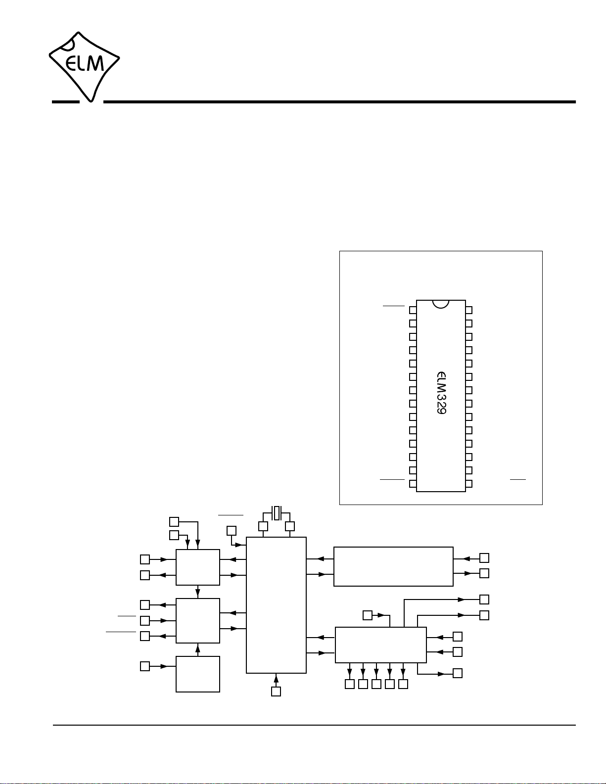
Connection Diagram
PDIP and SOIC
(top view)
OBD Tx LED
OBD Rx LED
RS232 Tx LED
RS232 Rx LED
CAN Rx
CAN Tx
M0
M1
VDD
RS232 Rx
RS232 Tx
PwrCtrl / Busy
MCLR
Memory
Baud Rate
LFmode
Active LED
XT1
XT2
VSS
In1
In2
Control
CAN Monitor
Vmeasure
VSS
Block Diagram IgnMon / RTSPwrCtrl
Command
and
Protocol
Interpreter
RS232
Interface
CAN Module
ISO 15765-4, SAE J1939
ISO 11898
4
4.00 MHz
9
10
Power
Control
15
16
14
PwrCtrl / Busy
IgnMon / RTS
PwrCtrl
11
CAN Monitor
/ A LED
Baud Rate
6
LFmode
7
18
17
RS232Tx
RS232Rx
Control
Module
status LEDs
3
26
27
25
28
24
23
CAN Rx
CAN Tx
22
21
M0
M1
5
Memory
1
MCLR
12
13
In1
In2
Control
2
Vmeasure
CAN
Monitor

ELM329
Elm Electronics – Circuits for the Hobbyist
www.elmelectronics.com 2 of 83
ELM329DSC
The Basics Description...................................................................................1
Features.......................................................................................1
Applications..................................................................................1
Block Diagram..............................................................................1
Connection Diagram.................................................................... 1
Pin Descriptions...........................................................................4
Unused Pins.................................................................................6
Absolute Maximum Ratings......................................................... 6
Electrical Characteristics..............................................................7
Using the ELM329 Overview......................................................................................8
Communicating with the ELM329................................................ 8
AT Commands...........................................................................10
AT Command Summary.............................................................10
AT Command Descriptions........................................................12
Reading the Battery Voltage......................................................26
OBD Commands........................................................................27
Talking to the Vehicle.................................................................28
Interpreting Trouble Codes........................................................ 30
Resetting Trouble Codes........................................................... 31
Quick Guide for Reading Trouble Codes...................................31
Selecting Protocols.................................................................... 32
OBD Message Formats..............................................................33
Setting the Header / ID Bits........................................................35
ISO 157645-4 Message Types.................................................. 37
Multiline Responses...................................................................38
Multiple PID Requests................................................................39
Receive Filtering - the CRA command.......................................40
Using the Mask and Filter.......................................................... 41
Monitoring the Bus.....................................................................42
Mixed ID (11 and 29 bit) Sending...............................................43
Restoring Order..........................................................................44
Advanced Features Using Higher RS232 Baud Rates...............................................45
Setting Timeouts - the AT ST and AT AT Commands...............47
SAE J1939 Messages................................................................48
Using J1939...............................................................................50
The FMS Standard.....................................................................54
The NMEA 2000 Standard.........................................................54
Periodic (Wakeup) Messages....................................................55
Altering Flow Control Messages................................................ 56
Using CAN Extended Addresses...............................................57
CAN Input Frequency Matching.................................................58
CAN (Single Wire) Transceiver Modes......................................59
Contents

ELM329
Elm Electronics – Circuits for the Hobbyist
www.elmelectronics.com 3 of 83
ELM329DSC
Contents (continued)
Advanced Features The CAN Monitor (pin 11)..........................................................60
(continued) Control Module Operation..........................................................60
Low Power Mode....................................................................... 61
Programmable Parameters........................................................64
Programmable Parameter Summary......................................... 65
Design Discussions Compatibility with the ELM327...................................................70
Modifications for Low Power Standby Operation.......................70
Maximum CAN Data Rates........................................................71
Microprocessor Interfaces..........................................................73
Example Applications.................................................................74
Figure 9 - A CAN to USB Interpreter................................... 75
Figure 10 - Parts List for Figure 9........................................76
Figure 11 - A Low Speed RS232 Interface..........................77
Figure 12 - A High Speed RS232 Interface.........................77
Figure 13 - An Alternative USB Interface............................ 78
Misc. Information Error Messages and Alerts.........................................................79
Outline Diagrams....................................................................... 81
Ordering Information..................................................................81
Copyright and Disclaimer...........................................................81
Index.......................................................................................... 82

ELM329
Elm Electronics – Circuits for the Hobbyist
www.elmelectronics.com
Pin Descriptions
4 of 83
MCLR (pin 1)
A momentary (>2µsec) logic low applied to this input
will reset the ELM329. If unused, this pin should be
connected to a logic high (VDD) level.
Vmeasure (pin 2)
This analog input is used to measure a 0 to 5V
signal that is applied to it. The value measured is
scaled by a factor of about 5.7 and may be displayed
using the AT RV command.
Care must be taken to prevent the voltage from
going outside of the supply levels of the ELM329, or
damage may occur. If it is not used, this pin should
be tied to either VDD or VSS.
Active LED (pin 3)
This output pin is normally at a high level, and is
driven to a low level when the ELM329 has
determined that it has found a valid (active) protocol.
The output is suitable for directly driving most LEDs
through a current limiting resistor, or interfacing to
other logic circuits. If unused, this pin may be left
open-circuited.
Note that the behaviour of this pin when the ELM329
is in the low power mode may be modified by the
logic level at pin 11, or with PP 0F, bit 4.
Control (pin 4)
The level at this output may be directly controlled
through AT commands. After any reset (powerup,
AT Z, etc.), the output reverts to low level.
Pin 4 may also be used to provide an output signal
that follows the internal CAN monitor output, by
setting bit 0 of PP 0F to 1. This is a new feature with
v2.0, and is not available with v1.0 ICs.
Memory (pin 5)
This input controls the default state of the memory
option. If this pin is at a high level during power-up or
reset, the memory function will be enabled by
default. If it is at a low level, then the default will be
to have it disabled. Memory can always be enabled
or disabled with the AT M1 and AT M0 commands.
Baud Rate (pin 6)
This input controls the baud rate of the RS232
interface. If it is at a high level during power-up or
reset, the baud rate will be set to 38400 (or the rate
that has been set by PP 0C). If at a low level, the
baud rate will always be 9600 bps.
LFmode (pin 7)
This input is used to select the default linefeed mode
to be used after a power-up or system reset. If it is at
a high level, then by default messages sent by the
ELM329 will be terminated with both a carriage
return and a linefeed character. If it is at a low level,
lines will be terminated by a carriage return only.
This behaviour can always be modified by issuing an
AT L1 or AT L0 command.
VSS (pin 8)
Circuit common must be connected to this pin.
XT1 (pin 9) and XT2 (pin 10)
A 4.000 MHz oscillator crystal is connected between
these two pins. Loading capacitors as required by
the crystal (typically 27pF each) will also need to be
connected from each of these pins to circuit common
(Vss).
When laying out a printed circuit board, you may
wish to consider placing a guard ring around the
oscillator crystal, pins, and capacitors, to provide a
little isolation between them and the other signals
(particularly the pin 11 CAN input).
Note that this device has not been configured for
operation with an external oscillator, and it expects a
crystal to be connected to these pins. Use of an
external clock source is not recommended. Also,
note that this oscillator is turned off when in the low
power or ‘standby’ mode of operation.
CAN Monitor and A LED (pin 11)
This input serves two functions. If a CAN signal is
detected at this pin, the ELM329 assumes that you
wish it to monitor that signal, and possibly control the
low power operation based on it.
If no CAN signal is detected, the ELM329 assumes
that you are using this pin to control the behaviour of
the Active LED output when the IC is in the low
power mode (as it did for v1.0 ICs). In this mode, if
pin 11 is at a high level when low power operation
begins, the Active LED output will continually flash
for about 16 msec every 4 seconds. If the input is at
a low level when low power operation begins, the
ELM329DSC

Elm Electronics – Circuits for the Hobbyist
www.elmelectronics.com 5 of 83
ELM329DSC
Active LED output will be off (high) when in low
power mode. If a CAN signal was detected on pin
11, the operation of the Active LED during low power
is determined by PP 0F, bit 4.
Monitoring for a CAN signal (ie. transitions at this
input pin) is a continuous background process that
can not be disabled.
In1 and In2 (pins 12 and 13)
These two inputs may be used for the monitoring of
logic level signals. Simple AT commands may be
used to read the level at either pin. No special
amplification is required, as the inputs have Schmitt
trigger wave shaping.
PwrCtrl (pin 14)
This output provides a level that is the inverse of that
of the PwrCtrl output (pin 16). If the low power mode
is disabled (ie if bit 7 of PP 0E is set to ‘0’), this
output still provides the inverse of the level set by
PP 0E b6. To provide a ‘soft start’ feature, pin 14 will
always change state 50 msec before pin 16.
IgnMon / RTS (pin 15)
This input pin can serve one of two functions,
depending on how the Power Control options
(PP 0E) are set.
If both bit 7 and bit 2 of PP 0E are set to ‘1’, this pin
will act as an Ignition Monitor. This will result in a
switch to the low power mode of operation, if the
input goes to a low level, as would happen if the
vehicle’s ignition were turned off. An internal
‘debounce’ timer is used to ensure that the ELM329
does not shut down for noise at the input.
When the voltage at pin 15 is again restored to a
high level, and a time of 1 or 5 seconds (as set by
PP 0E bit 1) passes, the ELM329 will return to
normal operation. A low to high transition at pin 15
will always restore normal operation, regardless of
the setting of PP 0E bit 2, or whether pin 15 was the
initial cause for the low power mode. This feature
allows a system to control how and when it switches
to low power standby operation, but still have
automatic wakeup by the ignition voltage, or by a
pushbutton.
If either bit 7 or bit 2 of PP 0E are ‘0’, this pin will
function as an active low ‘Request To Send’ input.
This can be used to interrupt the OBD processing in
order to send a new command, or if connected to
ignition positive, to highlight the fact that the ignition
has been turned off. Normally kept at a high level,
this input is brought low for attention, and should
remain so until the Busy line (pin 16) indicates that
the ELM329 is no longer busy, or until a prompt
character is received (if pin 16 is being used for
power control).
This input has Schmitt trigger wave shaping. By
default, pin 15 acts as the RTS interrupt input.
PwrCtrl / Busy (pin 16)
This output pin can serve one of two functions,
depending on how the Power Control options
(PP 0E) are set.
If bit 7 of PP 0E is a ‘1’ (the default), this pin will
function as a Power Control output. The normal state
of the pin will be as set by PP 0E bit 6, and the pin
will remain in that state until the ELM329 switches to
the low power mode of operation. This output is
typically used to control enable inputs, but may also
be used for relay circuits, etc. with suitable buffering.
The discussion on page 70 (‘Modifications for Low
Power Standby Operation’) provides more detail on
how to use this output.
If bit 7 of PP 0E is a ‘0’, pin 16 will function as a
‘Busy’ output, showing when the ELM329 is actively
processing a command (the output will be at a high
level), or when it is idle, ready to receive commands
(the output will be low).
By default, pin 16 provides the PwrCtrl function.
RS232Tx (pin 17)
This is the RS232 data transmit output. The signal
level is compatible with most interface ICs (the
output is high when idle), and there is sufficient
current drive to allow interfacing using only a PNP
transistor, if desired.
RS232Rx (pin 18)
This is the RS232 receive data input. The signal
level is compatible with most interface ICs (when at
idle, the level should be high), but can be used with
other interfaces as well, since the input has Schmitt
trigger wave shaping.
VSS (pin 19)
Circuit common must be connected to this pin.
Pin Descriptions (continued)
ELM329

Absolute Maximum Ratings
Storage Temperature.......................-65°C to +150°C
Ambient Temperature with
Power Applied....................................-40°C to +85°C
Voltage on VDD with respect to VSS..... -0.3V to +7.5V
Voltage on any other pin with
respect to VSS........................... -0.3V to (VDD + 0.3V)
Note:
These values are given as a design guideline only.
The ability to operate to these levels is neither
inferred nor recommended, and stresses beyond
those listed here will likely damage the device.
6 of 83ELM329DSC Elm Electronics – Circuits for the Hobbyist
www.elmelectronics.com
ELM329
VDD (pin 20)
This pin is the positive supply pin, and should always
be the most positive point in the circuit. Internal
circuitry connected to this pin is used to provide
power on reset of the microprocessor, so an external
reset signal is not required. Refer to the Electrical
Characteristics section for further information.
M1 (pin 21) and M0 (pin 22)
These two output pins are provided for use with CAN
transceiver ICs, as are typically used for Single Wire
CAN applications. The ELM329 will set both outputs
to a high level (‘Normal’) after startup, but the level at
these pins may be changed at any time with the
AT TM commands, and the level after powerup may
be set with PP20.
CAN Tx (pin 23) and CAN Rx (pin 24)
These are the two CAN interface signals that must
be connected to a CAN transceiver IC (see the
Example Applications section for more information).
If unused, pin 24 must be connected to a logic high
(VDD) level.
RS232 Rx LED (pin 25), RS232 Tx LED (pin 26),
OBD Rx LED (pin 27) and OBD Tx LED (pin 28)
These four output pins are normally high, and are
driven to low levels when the ELM329 is transmitting
or receiving data. These outputs are suitable for
directly driving most LEDs through current limiting
resistors, or interfacing to other logic circuits. If
unused, these pins may be left open-circuited.
Note that pin 28 can also be used to turn off all of the
Programmable Parameters, if you can not do so by
using the normal interface - see page 65 for more
details.
Pin Descriptions (continued)
Unused Pins
When people only want to implement a portion of what the ELM329 is capable of, they often ask what to do with the
unused pins. The rule is that unused outputs may be left open-circuited with nothing connected to them, but unused
inputs must be terminated. The ELM329 is a CMOS integrated circuit that can not have any inputs left floating (or
you might damage the IC). Connect unused inputs as follows:
1 2 5 6 7 11 12 13 15 18 24Pin
Level H H H H* * * * * * *
The inputs that are shown with an asterisk (*) may be connected to either a High (VDD) or a Low (VSS) level.

Electrical Characteristics
7 of 83ELM329DSC Elm Electronics – Circuits for the Hobbyist
www.elmelectronics.com
Notes: 1. This integrated circuit is based on Microchip Technology Inc.’s PIC18F2480 device. For more detailed
device specifications, refer to the Microchip documentation (available at http://www.microchip.com/).
2. This spec must be met in order to ensure that a correct power on reset occurs. It is quite easily achieved
using most common types of supplies, but may be violated if one uses a slowly varying supply voltage, as
may be obtained through direct connection to solar cells or some charge pump circuits.
All values are for operation at 25°C and a 5V supply, unless otherwise noted. For further information, refer to note 1 below.
Characteristic Minimum Typical Maximum ConditionsUnits
Supply voltage, VDD 4.2 5.0 5.5 V
VDD rate of rise 0.05 V/ms
Average current, IDD 12 mA
Input logic levels 0.8
3.0
V
Output low voltage
Output high voltage
current (sink) = 10 mA
current (source) = 10 mA
see note 2
AT RV to beginning of response
ELM329 device only - does not
include any load currents
Schmitt trigger
input thresholds
Brown-out reset voltage 2.65 2.79 2.93 V
rising
falling
A/D conversion time 9 msec
Pins 5, 6, 7, and 24 only
V
V
0.3
4.4
V
V
2.9
1.5
Pins 1, 11, 12, 13, 15 and 18 only
1.0
4.0
ELM329
IgnMon debounce time
AT LP to PwrCtrl output time
LP ALERT to PwrCtrl output time 2.0 sec
msec
sec
50
1.0
0.15 mA
normal
low power
Pin 18 low level pulse duration to
wake the IC from low power mode µsec128 -
65
low
high VVDD
VSS
Reset time
AT WS 1.0 msec
sec1.0AT Z Measured from the end of the
command to the start of the ID
message (ELM329 v2.1)

8 of 83
ELM329
ELM329DSC Elm Electronics – Circuits for the Hobbyist
www.elmelectronics.com
Communicating with the ELM329
The ELM329 expects to communicate with a PC
through an RS232 serial connection. Although modern
computers do not usually provide a serial connection
such as this, there are several ways in which a ‘virtual
serial port’ can be created. The most common devices
are USB to RS232 adapters, but there are several
others such as PC cards, ethernet devices, or
Bluetooth to serial adapters.
No matter how you physically connect to the
ELM329, you will need a way to send and receive
data. The simplest method is to use one of the many
‘terminal’ programs that are available (HyperTerminal,
ZTerm, etc.), to allow typing the characters directly
from your keyboard.
To use a terminal program, you will need to adjust
several settings. First, ensure that your software is set
to use the proper ‘COM’ port, and that you have
chosen the proper data rate - this will be either 9600
baud (if pin 6 = 0V at power up), or 38400 baud (if
pin 6 = 5V and PP 0C has not been changed). If you
select the wrong ‘COM’ port, you will not be able to
send or receive any data. If you select the wrong data
rate, the information that you send and receive will be
all garbled, and unreadable by you or the ELM329.
Don’t forget to also set your connection for 8 data bits,
no parity bits, and 1 stop bit, and to set it for the proper
‘line end’ mode. All of the responses from the ELM329
are terminated with a single carriage return character
and, optionally, a linefeed character (depending on
your settings).
Properly connected and powered, the ELM329 will
energize the five LED outputs in sequence (as a lamp
test) and will then send the message:
ELM329 v2.1
>
In addition to identifying the version of this IC,
receiving this string is a good way to confirm that the
computer connections and terminal software settings
are correct (however, at this point no communications
have taken place with the vehicle, so the state of that
connection is still unknown).
The ‘>’ character that is shown on the second line
is the ELM329’s prompt character. It indicates that the
device is in the idle state, ready to receive characters
on the RS232 port. If you did not see the identification
string, you might try resetting the IC again with the AT
Z (reset) command. Simply type the letters A T and Z
(spaces are optional), then press the return key:
>AT Z
That should cause the LEDs to flash again, and
the identification string to be printed. If you see strange
looking characters, then check your baud rate - you
have likely set it incorrectly.
Characters sent from the computer can either be
intended for the ELM329’s internal use, or for
reformatting and passing on to the vehicle. The
ELM329 can quickly determine where the received
characters are to be directed by monitoring the
contents of the message. Commands that are
intended for the ELM329’s internal use will begin with
the characters ‘AT’, while OBD commands for the
vehicle are only allowed to contain the ASCII codes for
hexadecimal digits (0 to 9 and A to F).
Whether it is an ‘AT’ type internal command or a
hex string for the OBD bus, all messages to the
ELM329 must be terminated with a carriage return
character (hex ‘0D’) before it will be acted upon. The
one exception is when an incomplete string is sent and
no carriage return appears. In this case, an internal
timer will automatically abort the incomplete message
after about 20 seconds, and the ELM329 will print a
single question mark (‘?’) to show that the input was
not understood (and was not acted upon).
Messages that are not understood by the ELM329
Overview
The following describes how to use the ELM329 to
obtain information from your vehicle.
We begin by discussing just how to ‘talk’ to the IC
using a PC, then explain how to change options using
‘AT’ commands, and finally we show how to use the
ELM329 to obtain trouble codes (and reset them). For
the more advanced experimenters, there are also
sections on how to use some of the other features of
this product as well.
Using the ELM329 is not as daunting as it first
seems. Many users will never need to issue an ‘AT’
command, adjust timeouts, or change the headers. For
most, all that is required is a PC or smart device with a
terminal program (such as HyperTerminal or ZTerm),
and a little knowledge of OBD commands, which we
will provide in the following sections…

Communicating with the ELM329 (continued)
(syntax errors) will always be signalled by a single
question mark. These include incomplete messages,
incorrect AT commands, or invalid hexadecimal digit
strings, but are not an indication of whether or not the
message was understood by the vehicle. One must
keep in mind that the ELM329 is a protocol interpreter
that makes no attempt to assess the OBD messages
for validity – it only ensures that hexadecimal digits
were received, combined into bytes, then sent out the
OBD port, and it does not know if a message sent to
the vehicle was in error.
While processing OBD commands, the ELM329
will continually monitor for either an active RTS input
(if enabled), or an RS232 character received. Either
one can interrupt the IC, quickly returning control to
the user, while possibly aborting any initiation, etc. that
was in progress. After generating a signal to interrupt
the ELM329, software should always wait for either the
prompt character (‘>’ or hex 3E), or a low level on the
Busy output before beginning to send the next
command.
Finally, it should be noted that the ELM329 is not
case-sensitive, so the commands ‘ATZ’, ‘atz’, and
‘AtZ’ are all exactly the same to the ELM329. All
commands may be entered as you prefer, as no one
method is faster or better. The ELM329 also ignores
space characters and all control characters (tab, etc.),
so they can be inserted anywhere in the input if that
improves readability.
One other feature of the ELM329 is the ability to
repeat the last command (AT or OBD) when only a
single carriage return character is received. If you
have sent a command (for example, 01 0C to obtain
the rpm), you do not have to resend the entire
command in order to obtain an update from the vehicle
- simply send a carriage return character, and the
ELM329 will repeat the command for you. The
memory buffer only remembers the previous command
- there is no provision in the current ELM329 to
provide storage for any more.
9 of 83
ELM329
ELM329DSC Elm Electronics – Circuits for the Hobbyist
www.elmelectronics.com
Please Note:
There is a very small chance that NULL characters (byte value 00) may occasionally
be inserted into the RS232 data that is transmitted by the ELM329.
Microchip Technology has reported that some ICs which use the same EUSART as
in the ELM329 may, under very specific (and rare) conditions, insert an extra byte
(always of value 00) into the transmitted data. If you are using a terminal program to view
the data, you should select the ‘hide control characters’ option if it is available, and if you
are writing software for the ELM329, then monitor incoming bytes, and ignore any that
are of value 00 (ie. remove NULLs).

Several parameters within the ELM329 can be
adjusted in order to modify its behaviour. These do not
normally have to be changed before attempting to talk
to the vehicle, but occasionally the user may wish to
customize these settings – for example by turning the
character echo off, adjusting a timeout value, or
changing the header (ID) bytes. In order to do this,
internal ‘AT’ commands must be used.
Those familiar with PC modems will immediately
recognize AT commands as a standard way in which
modems are internally configured. The ELM329 uses
essentially the same method, always watching the
data sent by the PC, looking for messages that begin
with the character ‘A’ followed by the character ‘T’. If
found, the next characters will be interpreted as an
internal configuration or ‘AT’ command, and will be
executed upon receipt of a terminating carriage return
character. If the command is just a setting change, the
ELM329 will reply with the characters ‘OK’, to say that
it was successfully completed.
Some of the commands require that numbers be
provided as arguments, in order to set the internal
values. These will always be hexadecimal numbers
which must generally be provided in pairs. The
hexadecimal conversion chart in the OBD Commands
section (page 27) may be helpful if you wish to
interpret the values. Also, one should be aware that for
the on/off types of commands, the second character is
the number 1 or the number 0, the universal terms for
on and off.
The remainder of this page, and the next page
following provide a summary of all of the commands
that the current version of the ELM329 recognizes. A
more complete description of each command begins
on page 12.
10 of 83
ELM329
ELM329DSC Elm Electronics – Circuits for the Hobbyist
www.elmelectronics.com
AT Command Summary
AT Commands
ELM329 Options
<CR> repeat the last command
BRD hh try Baud Rate Divisor hh
BRT hh set Baud Rate Timeout
Dset all to Defaults
E0, E1 Echo off, or on*
Iprint the version ID
L0, L1 Linefeeds off, or on
LP go to low power mode
M0, M1 Memory off, or on
RD Read the stored Data
SD hh Save Data byte hh
WS Warm Start (quick software reset)
Zreset all
@1 display the device description
@2 display the device identifier
@3 cccccccccccc store the @2 identifier
Programmable Parameters
PP xx OFF disable Prog Parameter xx
PP FF OFF all Prog Parameters disabled
PP xx ON enable Prog Parameter xx
PP FF ON all Prog Parameters enabled
PP xx SV yy for PP xx, Set the Value to yy
PPS print a PP Summary
Voltage Readings
CV dddd Calibrate the Voltage to dd.dd volts
CV 0000 restore CV value to factory setting
RV Read the input Voltage
Other
C0, C1 Control Output off*, or on
IGN read the IgnMon input level
IN1 read INput 1 level
IN2 read INput 2 level
Note: Settings shown with an asterisk (*)
are the default values

11 of 83
ELM329
ELM329DSC Elm Electronics – Circuits for the Hobbyist
www.elmelectronics.com
AT Command Summary (continued)
General OBD Commands
AT0, 1, 2 Adaptive Timing off, auto1*, auto2
BD perform a Buffer Dump
BI Bypass the Initialization sequence
DP Describe the current Protocol
DPN Describe the Protocol by Number
H0, H1 Headers off*, or on
MA Monitor All
PC Protocol Close
R0, R1 Responses off, or on*
S0, S1 printing of Spaces off, or on*
SH xyz Set Header (11 bit ID) to xyz
SH xxyyzz Set Header (29 bit ID) to xxyyzz
SH wwxxyyzz Set Header (29 bit ID) to wwxxyyzz
SP h Set Protocol to h and save it
SP Ah Set Protocol to Auto, h and save it
ST hh Set Timeout to hh x 4 msec
TA hh set Tester Address to hh
TP h Try Protocol h
TP Ah Try Protocol h with Auto search
J1939 CAN Specific Commands (protocols A to F)
DM1 monitor for DM1 messages
JE use J1939 Elm data format*
JHF0, JHF1 Header Formatting off, or on*
JS use J1939 SAE data format
JTM1 set Timer Multiplier to 1*
JTM5 set Timer Multiplier to 5
MP hhhh Monitor for PGN 0hhhh
MP hhhh n “ “ and get n messages
MP hhhhhh Monitor for PGN hhhhhh
MP hhhhhh n “ “ and get n messages
CAN Specific Commands (protocols 6 to F)
. [1 - 8 bytes] send bytes with the 11 bit ID
: [1 - 8 bytes] send bytes with the 29 bit ID
CA is there CAN Activity at pin 11?
CEA turn off CAN Extended Addressing
CEA hh use CAN Extended Address hh
CAF0, CAF1 Automatic Formatting off, or on*
CF hhh set the ID Filter to hhh
CF hhhhhhhh set the ID Filter to hhhhhhhh
CFC0, CFC1 Flow Controls off, or on*
CM hhh set the ID Mask to hhh
CM hhhhhhhh set the ID Mask to hhhhhhhh
CP hh set CAN Priority to hh (29 bit)
CRA reset the Receive Address filters
CRA hhh set CAN Receive Address to hhh
CRA hhhhhhhh set the Rx Address to hhhhhhhh
CS show the CAN Status counts
CSM0, CSM1 Silent Monitoring off, or on*
D0, D1 display of the DLC off*, or on
FC SD [1 - 8 bytes] FC, Set Data to [...]
FC SM h Flow Control, Set the Mode to h
FC SH hhh FC, Set the Header to hhh
FC SH hhhhhhhh “ “ hhhhhhhh
PB xx yy Protocol B options and baud rate
TM0, 1, 2, 3 set Transceiver Mode to 0,1,2, or 3*
RTR send an RTR message
V0, V1 use of Variable DLC off*, or on
Periodic Message Commands
SW hh Set Wakeup interval to hhx20 msec
SW 00 turn off Wakeup messages
WD [1 - 8 bytes] set the Wakeup Data
WH hhh set the Wakeup Header (11 bit)
WH hhhhhhhh set the Wakeup Header (29 bit)
WM [1 - 8 bytes] set the Wakeup Message
WM0, 1, 2 set the Wakeup Mode to 0*, 1 or 2
Note: Settings shown with an asterisk (*)
are the default values

12 of 83
ELM329
ELM329DSC Elm Electronics – Circuits for the Hobbyist
www.elmelectronics.com
AT Command Descriptions
<CR> [ repeat the last command ]
Sending a single carriage return character causes
the ELM329 to repeat the last command that it
performed. This is typically used when you wish to
obtain updates to a value at the fastest possible rate -
for example, if you send 01 0C to obtain the engine
rpm, you need only send a carriage return character
each time you wish to receive an update.
Do not use ‘AT’ before this command.
. [1 - 8 bytes] [ send bytes with the 11 bit ID ]
If your currently active protocol uses a 29 bit ID,
there may be times when you would like to send a
single message that has an 11 bit ID. This command is
used for that.
A single period (‘.’) followed by 1 to 8 data bytes
will cause the ELM329 to send those data bytes along
with the currently defined 11 bit ID. The data will be
sent exactly as provided - no formatting bytes or filler
bytes will be added, and the number of data bytes sent
will be the same as what you provide (so if you need to
send 8 bytes as for ISO 15765, then you must provide
all 8 of them). The default value used for the 11 bit ID
is 7DF, but this may be changed with the AT SH xyz
command. See the ‘Mixed ID (11 and 29 bit) Sending’
section for more information.
A protocol must be active before you can use this
command, as the ELM329 needs to know the current
baud rate, etc., but it does not have to be a 29 bit one.
That is, you may use this ‘dot’ command with an 11 bit
ID protocol, for example, if you needed to send
unformatted data along with ISO 15765 formatted data
(but the current firmware only allows you to define one
11 bit ID/header).
Do not use ‘AT’ before this command.
: [1 - 8 bytes] [ send bytes with the 29 bit ID ]
If your currently active protocol uses an 11 bit ID,
there may be times when you would like to send a
single message that has a 29 bit ID. This command is
used for that.
A single colon (‘:’) followed by 1 to 8 data bytes
will cause the ELM329 to send those data bytes along
with the currently defined 29 bit ID. The data will be
sent exactly as provided - no formatting bytes or filler
bytes will be added, and the number of data bytes sent
will be the same as what you provide (so if you need to
send 8 bytes as for ISO 15765, then you must provide
all 8 of them). The default value used for the 29 bit ID
is 18 DB 33 F1, but this may be changed with the
AT SH xxyyzz or AT SH wwxxyyzz commands. See
the ‘Mixed ID (11 and 29 bit) Sending’ section for more
information.
A protocol must be active before you can use this
command, as the ELM329 needs to know the current
baud rate, etc., but it does not have to be an 11 bit
one. That is, you may use this ‘colon’ command with a
29 bit ID protocol, for example, if you needed to send
unformatted data along with ISO 15765 formatted data
(but the current firmware only allows you to define one
29 bit ID/header).
Do not use ‘AT’ before this command.
AT0, AT1 and AT2 [ Adaptive Timing control ]
After an OBD request has been sent, the ELM329
waits to see if any responses are coming from the
vehicle. The maximum time that it waits is set by the
AT ST hh setting, but this setting is purposely a little
longer than it needs to be, in order to ensure that the
IC will work with a wide variety of vehicles. Although
the setting is adjustable, many people do not have the
equipment or experience that it would take to
determine an optimal value.
The Adaptive Timing feature automatically sets the
timeout value for you, to a value that is based on the
actual response times that your vehicle is responding
in. As conditions such as bus loading, etc. change, the
algorithm learns from them, and makes appropriate
adjustments. Note that it always uses your AT ST hh
setting as the maximum setting, and will never choose
one which is longer.
There are three adaptive timing settings that are
available for use. By default, Adaptive Timing option 1
(AT1) is enabled, and is the recommended setting.
AT0 is used to disable Adaptive timing (so the timeout
The following describes each AT Command that the
current version of the ELM329 supports, in a little more
detail. Many of these commands are also described
further in other sections:

13 of 83
ELM329
ELM329DSC Elm Electronics – Circuits for the Hobbyist
www.elmelectronics.com
AT Command Descriptions (continued)
is always as set by AT ST), while AT2 is a more
aggressive version of AT1 (the effect is more
noticeable for very slow connections – you may not
see much difference with faster OBD systems). The
J1939 protocol does not support Adaptive Timing – it
uses fixed timeouts as set in the standard.
BD [ perform an OBD Buffer Dump ]
All messages sent and received by the ELM329
are stored temporarily in a set of twelve memory
storage locations called the OBD Buffer. Occasionally,
it may be useful to see the contents of this buffer,
perhaps to see why a request failed, to see the header
bytes in the last message, or just to learn more of the
structure of OBD messages. You can ask at any time
for the contents of this buffer to be ‘dumped’
(ie printed). When you do, the ELM329 sends a length
byte (representing the length of the current message in
the buffer) followed by the contents of all twelve OBD
buffer locations. For example, here’s one ‘dump’:
>AT BD
0C 00 00 07 E8 03 41 05 42 00 00 00 00
The 0C is the length byte - it tells us that the
following 12 bytes are valid. The actual bytes that have
been sent or received appear after the length. Note
that wakeup (CAN periodic) messages do not use the
buffer as an intermediate step, so you are not able to
see them with AT BD.
BI [ Bypass the Initialization sequence ]
This command should be used with caution. It
allows the currently selected protocol to be made
active without requiring any sort of initiation or
handshaking to occur. The initiation process is
normally used to validate the protocol, and without it,
results may be difficult to predict. It should not be used
for routine OBD use, and has only been provided to
allow the construction of ECU simulators and training
demonstrators.
BRD hh [ try Baud Rate Divisor hh ]
This command is used to change the RS232 baud
rate divisor to the hex value provided by hh, while
under computer control. It is not intended for casual
experimenting - if you wish to change the baud rate
from a terminal program, you should use PP 0C.
Since some interface circuits are not able to be
operated at high data rates, the BRD command uses a
sequence of sends and receives to test the interface,
with any failure resulting in a fallback to the previous
baud rate. This allows several baud rates to be tested
and a reliable one chosen for the communications.
The entire process is described in detail in the ‘Using
Higher RS232 Baud Rates’ section, on pages 45 and
46. If successful, the actual baud rate (in kbps) will be
4000 divided by the divisor (hh).
BRT hh [ set Baud Rate Timeout to hh ]
This command allows the timeout used for the
Baud Rate handshake (ie. AT BRD) to be varied. The
time delay is given by hh x 5.0 msec, where hh is a
hexadecimal value. The default value for this setting is
0F, providing a 75 msec timeout. Note that a value of
00 does not result in 0 msec - it provides the
maximum time of 256 x 5.0 msec, or 1.28 seconds.
C0 and C1 [ Control output off* or on ]
These commands are used to set the level at the
Control output (pin 4). The AT C0 command sets it to a
low logic level (0V), while AT C1 sets it to a high level
(5V). After a system reset or wakeup from low power
mode (unless PP 0F bit 0 = ‘1’), the Control output will
be reset to a low level.
CA [is there CAN Activity at pin 11?]
This command is used to determine if there is a
CAN signal present at pin 11 (the CAN Monitor pin). If
there is, the response will be the letter ‘Y’ (for yes),
while if there is no signal, the response will be the
letter ‘N’, for no. If there has been no signal detected
since the last reset, the output will be a dash (‘-’).
CAF0 and CAF1 [ CAN Auto Formatting off or on ]
These commands determine whether the ELM329
assists you with the formatting of the CAN data that is
sent and received. With CAN Automatic Formatting
enabled (CAF1), the IC will automatically generate the
formatting (PCI) bytes for you when sending, and will
remove them when receiving. This means that you can
continue to issue OBD requests (01 00, etc.), without
regard to the extra bytes that some CAN systems
require. Also, with formatting on, any extra (unused)

14 of 83
ELM329
ELM329DSC Elm Electronics – Circuits for the Hobbyist
www.elmelectronics.com
data bytes that are received in the frame will be
removed, and any messages with invalid PCI bytes will
be ignored. (When monitoring, however, messages
with invalid PCI bytes will be shown, with a ‘<DATA
ERROR’ message beside them).
Multi-frame responses may be returned by the
vehicle with ISO 15765 and J1939. To make these
more readable, the Auto Formatting mode will extract
the total data length and print it on one line, then show
each line of data with the segment number followed by
a colon (‘:’), and then the data bytes.
You may also see the characters 'FC:' on a line (if
you are experimenting). This identifies a Flow Control
message that has been sent as part of the multi-line
message signalling. Flow Control messages are
automatically generated by the ELM329 in response to
a ‘First Frame’ reply, as long as the CFC setting is on
(it does not matter if auto formatting is on or not).
Another type of message – the RTR (or ‘Remote
Transmission Request’) – will be automatically hidden
for you when in the CAF1 mode, since they contain no
data. When auto formatting is off (CAF0), you will see
the characters 'RTR' printed when one of these frames
has been received.
Turning the CAN Automatic Formatting off (CAF0),
will cause the ELM329 to print all of the received data
bytes. No bytes will be hidden from you, and none will
be inserted for you. Similarly, when sending a data
request with formatting off, you must provide all of the
required data bytes exactly as they are to be sent –
the ELM329 will not perform any formatting for you
other than to add some trailing 'padding' bytes to
ensure that eight data bytes are sent, if required. This
allows operation in systems that do not use PCI bytes.
Note that turning the display of headers on (with
AT H1) will override some of the CAF1 formatting of
the received data frames, so that the received bytes
will appear much like in the CAF0 mode (ie. as
received). It is only the printing of the received data
that will be affected when both CAF1 and H1 modes
are enabled, though; when sending data, the PCI byte
will still be created for you and padding bytes will still
be added. Auto Formatting on (CAF1) is the default
setting for the ELM329.
CEA [ turn off the CAN Extended Address ]
The CEA command is used to turn off the special
features that are set with the CEA hh command.
CEA hh [ set the CAN Extended Address to hh ]
Some CAN protocols extend the addressing fields
by using the first of the eight data bytes as a target or
receiver’s address. This type of formatting does not
comply with any OBD standard, but by adding it, we
allow for some experimentation.
Sending the CEA hh command causes the
ELM329 to insert the hh value as the first data byte of
all CAN messages that you send. It also adds one
more filtering step to received messages, only passing
ones that have the Tester Address in the first data byte
position (in addition to requiring that ID bits match the
patterns set by AT CF and CM, or CRA). The AT CEA
hh command can be sent at any time, and changes
are effective immediately, allowing for changes of the
address ‘on-the-fly’. There is a more lengthy
discussion of this extended addressing in the ‘Using
CAN Extended Addresses’ section on page 57.
The CEA mode of operation is off by default, and
once on, can be turned off at any time by sending AT
CEA, with no address. Note that the CEA setting has
no effect when J1939 formatting is on.
CF hhh [ set the CAN ID Filter to hhh ]
The CAN Filter works in conjunction with the CAN
Mask to determine what information is to be accepted
by the receiver. As each message is received, the
incoming CAN ID bits are compared to the CAN Filter
bits (when the mask bit is a ‘1’). If all of the relevant
bits match, the message will be accepted, and
processed by the ELM329, otherwise it will be
discarded. This version of the CAN Filter command is
used to set filters with 11 bit ID CAN systems. Only the
rightmost 11 bits of the provided nibbles are used, and
the most significant bit is ignored.
CF hh hh hh hh [ set the CAN ID Filter to hhhhhhhh ]
This command allows all four bytes (actually 29
bits) of a CAN Filter to be set at once. The 3 most
significant bits will always be ignored, and may be
given any value. This command may be used to create
11 bit ID filters as well, since they are stored in the
same locations internally (entering AT CF 00 00 0h hh
is exactly the same as entering the shorter AT CF hhh
command).
CFC0 and CFC1 [ CAN Flow Control off or on ]
The ISO 15765-4 CAN protocol expects a ‘Flow
AT Command Descriptions (continued)

15 of 83
ELM329
ELM329DSC Elm Electronics – Circuits for the Hobbyist
www.elmelectronics.com
Control’ message to always be sent in response to a
‘First Frame’ message, and the ELM329 automatically
sends these without any intervention by the user. If
experimenting with a non-OBD system, it may be
desirable to turn this automatic response off, and the
AT CFC0 command has been provided for that
purpose. The default setting is CFC1 - Flow Controls
on. Note that during monitoring (ie AT MA), there are
never any Flow Controls sent no matter what the CFC
option is set to.
CM hhh [ set the CAN ID Mask to hhh ]
There can be a great many messages being
transmitted in a CAN system at any one time. In order
to limit what the ELM329 views, there needs to be a
system of filtering out the relevant ones from all the
others. This is accomplished by the filter, which works
in conjunction with the mask. A mask is a group of bits
that show the ELM329 which bits in the filter are
relevant, and which ones can be ignored. A ‘must
match’ condition is signalled by setting a mask bit to
'1', while a 'don't care' is signalled by setting a bit to '0'.
This three digit variation of the CM command is used
to provide mask values for 11 bit ID systems (the most
significant bit is always ignored).
Note that a common storage location is used
internally for the 29 bit and 11 bit masks, so an 11 bit
mask could conceivably be assigned with the next
command (CM hh hh hh hh), should you wish to do the
extra typing.
CM hh hh hh hh [ set the CAN ID Mask to hhhhhhhh ]
This command is used to assign mask values for
29 bit ID systems. See the discussion under the
CM hhh command as it is essentially identical, except
for the length. Note that the three most significant bits
that you provide in the first digit will be ignored.
CP hh [ set CAN Priority bits to hh ]
This command is used to modify the five most
significant bits of a 29 bit CAN ID for sending
messages (the other 24 bits are set with one of the AT
SH commands). Many systems use these bits to
assign a priority value to messages, and to determine
the protocol. Any bits provided in excess of the five
required are ignored, and not stored by the ELM329 (it
only uses the five least significant bits of this byte).
The default value for these priority bits is hex 18,
which can be restored at any time with the AT D
command.
CRA [reset the CAN Rx Addr]
The AT CRA command is used to restore the CAN
receive filters to their default values. Note that it does
not have any arguments (ie no data).
CRA xyz [set the CAN Rx Addr to xyz]
Setting the CAN masks and filters can be difficult
at times, so if you only want to receive information
from one address (ie. one CAN ID), then this
command may be very welcome. For example, if you
only want to see information from 7E8, simply send AT
CRA 7E8, and the ELM329 will make the necessary
adjustments to both the mask and the filter for you.
If you wish to allow the reception of a range of
values, you can use the letter X to signify a ‘don’t care’
condition. That is, AT CRA 7EX would allow all IDs
that start with 7E to pass (7E0, 7E1, etc.). For a more
specific range of IDs, you may need to assign a mask
and filter.
CRA wwxxyyzz [set the CAN Rx Addr to wwxxyyzz]
This command is identical to the previous one,
except that it is used to set 29 bit CAN IDs, instead of
11. Sending AT CRA will also reverse the changes
made by this command.
CS [ show the CAN Status counts ]
The CAN protocol requires that statistics be kept
regarding the number of transmit and receive errors
detected. If there should be a significant number of
errors (due to a hardware or software problem), the
device will go off-line in order to not affect other data
on the bus. The AT CS command lets you see both
the transmitter (Tx) and the receiver (Rx) error counts,
in hexadecimal. If the transmitter should be off (count
>FF), you will see ‘OFF’ rather than a specific count.
CSM0 and CSM1 [ CAN Silent Monitoring off or on ]
The ELM329 was designed to be completely silent
while monitoring a CAN bus. Because of this, it is able
to report exactly what it sees, without colouring the
information in any way. Occasionally (when bench
testing, or when connecting to a dedicated CAN port),
it may be preferred that the ELM329 does not operate
AT Command Descriptions (continued)

16 of 83
ELM329
ELM329DSC Elm Electronics – Circuits for the Hobbyist
www.elmelectronics.com
silently (ie you may want it to generate ACK bits, etc.),
and this is what the CSM command is for. CSM1 turns
silent monitoring on (no ACKs), CSM0 turns it off. The
default value is CSM1, but it may be changed with
PP 21.
CV dddd [ Calibrate the Voltage to dd.dd volts ]
The voltage reading that the ELM329 shows for an
AT RV request can be calibrated with this command.
The argument (‘dddd’) must always be provided as 4
digits, with no decimal point (it assumes that the
decimal place is between the second and the third
digits).
To use this feature, simply use an accurate meter
to read the actual input voltage, then use the CV
command to change the internal calibration (scaling)
factor. For example, if the ELM329 shows the voltage
as 12.2V while you measure 11.99 volts, then send
AT CV 1199 and the ELM329 will recalibrate itself for
that voltage (it will actually read 12.0V due to digit
roundoff). See page 26 for some more information on
how to read voltages and perform the calibration.
CV 0000 [ restore the factory Calibration Value ]
If you are experimenting with the CV dddd
command but do not have an accurate voltmeter as a
reference, you may soon get into trouble. If this
happens, you can always send AT CV 0000 to restore
the ELM329 to the original calibration value.
D[ set all to Defaults ]
This command is used to set the options to their
default (or factory) settings, as when power is first
applied. The last stored protocol will be retrieved from
memory, and will become the current setting (possibly
closing a protocol that was active). Any settings that
the user had made for custom headers, filters, or
masks will be returned to their default values, and all
timer settings will also be restored to their defaults.
D0 and D1 [ display of DLC off or on ]
Standard CAN (ISO 15765-4) OBD requires that
all messages have 8 data bytes, so displaying the
number of data bytes (the DLC) is not normally very
useful. When experimenting with other protocols,
however, it may be useful to be able to see what the
data lengths are. The D0 and D1 commands control
the display of the DLC digit (the headers must also be
on in order to see this digit). When displayed, the
single DLC digit will appear between the ID (header)
bytes and the data bytes. The default setting is
determined by PP 29.
DM1 [ monitor for DM1s ]
The SAE J1939 Protocol broadcasts trouble codes
periodically, by way of the Diagnostic Mode 1 (DM1)
messages. This command sets the ELM329 to
continually monitor for this type of message for you,
even following multi-segment transport protocols if
required. Note that a combination of masks and filters
could be set to provide a similar output, but they would
not allow multiline messages to be detected. The DM1
command adds the extra logic that is needed for
multiline messages.
This command is only available when a protocol
has been selected for J1939 formatting. It returns an
error if attempted under any other conditions.
DP [ Describe the current Protocol ]
The ELM329 automatically detects a vehicle’s
OBD protocol, but does not normally report what it is.
The DP command is a convenient means of asking
what protocol the IC is currently set to (even if it has
not yet ‘connected’ to the vehicle).
If a protocol is chosen and the automatic option is
also selected, AT DP will show the word 'AUTO' before
the protocol description. Note that the description
shows the actual protocol names, and the data rates, it
does not provide the numbers used by the protocol
setting commands (see DPN for this).
DPN [ Describe the Protocol by Number ]
This command is similar to the DP command, but
it returns a number which represents the current
protocol. If the automatic search function is also
enabled, the number will be preceded with the letter
‘A’. The number is the same one that is used with the
set protocol and test protocol commands (see page 32
for a list of them).
E0 and E1 [ Echo off or on ]
These commands control whether or not the
characters received on the RS232 port are echoed
(retransmitted) back to the host computer. Character
echo can be used to confirm that the characters sent
AT Command Descriptions (continued)

to the ELM329 were received correctly. The default is
E1 (or echo on).
FC SD [1-8 bytes] [ Flow Control Set Data to… ]
The data bytes that are sent in a CAN Flow
Control message may be defined with this command.
One to eight data bytes may be specified, with the
remainder of the bytes in the message being
automatically set to the default CAN filler byte, if more
bytes are required by the protocol. Note that no
formatting bytes (PCI, etc.) are added by this
command - the data is used exactly as provided,
except for the filler bytes. AT FC SD is used with Flow
Control modes 1 and 2.
FC SH xyz [ Flow Control Set Header to… ]
The header (or more properly ‘CAN ID’) bytes
used for CAN Flow Control messages can be set using
this command. Only the right-most 11 bits of those
provided will be used - the most significant bit is
always ignored. This command only affects Flow
Control mode 1.
FC SH wwxxyyzz [ Flow Control Set Header to… ]
This command is used to set the header (or ‘CAN
ID’) bits for Flow Control responses with 29 bit CAN ID
systems. Since the 8 nibbles define 32 bits, only the
right-most 29 bits of those provided will be used - the
most significant three bits are always ignored. This
command only affects Flow Control mode 1.
FC SM h [ Flow Control Set Mode to h ]
This command sets how the ELM329 responds to
First Frame messages when automatic Flow Control
responses are enabled. The single digit provided can
either be ‘0’ (the default) for fully automatic responses,
‘1’ for completely user defined responses, or ‘2’ for
user defined data bytes in the response. Note that FC
modes 1 and 2 can only be enabled if you have
defined the needed data and possibly ID bytes. If you
have not, you will get an error message. More
complete details and examples can be found in the
Altering Flow Control Messages section (page 56).
H0 and H1 [ Headers off or on ]
These commands control whether or not the
header (ID and possibly DLC) bytes of information are
shown in the responses from the vehicle. These are
not normally shown by the ELM329, but may be of
interest (especially if you receive multiple responses
and wish to determine what modules they were from).
Turning the headers on (with AT H1) actually
shows more than just the header bytes – you will see
the complete message as transmitted, including the
PCI bytes, and the CAN data length code (DLC) if it
has been enabled. The current version of this IC does
not display the CAN CRC code.
I[ Identify yourself ]
Issuing this command causes the chip to identify
itself, by printing the startup product ID string (currently
‘ELM329 v2.1’). Software can use this to determine
exactly which integrated circuit it is talking to, without
having to reset the IC.
IGN [ read the IgnMon input level ]
This command reads the signal level at pin 15. It
assumes that the logic level is related to the ignition
voltage, so if the input is at a high level, the response
will be ‘ON’, and a low level will report ‘OFF’. This
feature is most useful if you wish to perform the power
control functions using your own software. If you
disable the automatic response to a low input on this
pin (by setting bit 2 of PP 0E to 0), then pin 15 will
function as the RTS input. A low level on the input will
not turn the power off, but it will interrupt any OBD
activity that is in progress. All you need to do is detect
the ‘STOPPED’ message that is sent when the
ELM329 is interrupted, and then check the level at pin
15 using AT IGN. If it is found to be OFF, you can
perform an orderly shutdown yourself.
IN1 [ read the level at INput 1 ]
This command causes the ELM329 to read the
logic level at pin 12. If it is at a low level, ‘0’ will be
reported, while a high level results in a ‘1’. The level
shown is subject to the hysteresis effects of the
Schmitt trigger wave shaping of the input circuitry.
IN2 [ read the level at INput 2 ]
This command causes the ELM329 to read the
logic level at pin 13. If it is at a low level, ‘0’ will be
reported, while a high level results in a ‘1’. The level
shown is subject to the hysteresis effects of the
Schmitt trigger wave shaping of the input circuitry.
17 of 83
ELM329
ELM329DSC Elm Electronics – Circuits for the Hobbyist
www.elmelectronics.com
AT Command Descriptions (continued)

18 of 83
ELM329
ELM329DSC Elm Electronics – Circuits for the Hobbyist
www.elmelectronics.com
JE [ enables the J1939 ELM data format ]
The J1939 standard requires that PGN requests
be sent with the byte order reversed from the standard
‘left-to-right’ order, which many of us would expect. For
example, to send a request for the engine temperature
(PGN 00FEEE), the data bytes are actually sent in the
reverse order (ie EE FE 00), and the ELM329 would
normally expect you to provide the data in that order
for passing on to the vehicle.
When experimenting, this constant need for byte
reversals can be quite confusing, so we have defined
an ELM format that reverses the bytes for you. When
the J1939 ELM (JE) format is enabled, and you have a
J1939 protocol selected, and you provide three data
bytes to the ELM329, it will reverse the order for you
before sending them to the ECU. To request the
engine temperature PGN, you would send 00 FE EE
(and not EE FE 00). The ‘JE’ type of automatic
formatting is enabled by default.
JHF0 and JHF1 [ J1939 Header Formatting off or on ]
When printing responses, the ELM329 normally
formats the J1939 ID (ie Header) bits in such a way as
to isolate the priority bits and group all the PGN
information, while keeping the source address byte
separate. If you prefer to see the ID information as four
separate bytes (which a lot of the J1939 software
seems to do), then simply turn off the formatting with
JHF0. The CAF0 command has the same effect (and
overrides the JHF setting), but also affects other
formatting. The default setting is JHF1.
JS [ enables the J1939 SAE data format ]
The AT JS command disables the automatic byte
reordering that the JE command performs for you. If
you wish to send data bytes to the J1939 vehicle
without any manipulation of the byte order, then select
JS formatting.
Using the above example for engine temperature
(PGN 00FEEE) with the data format set to JS, you
must send the bytes to the ELM329 as EE FE 00 (this
is also known as little-endian byte ordering).
The JS type of data formatting is off by default.
JTM1 [ J1939 Timer Multiplier to 1 ]
This command sets the J1939 AT ST time
multiplier to 1, reversing any changes made by JTM5.
JTM1 is the default setting. It has no effect for non-
J1939 protocols.
JTM5 [ J1939 Timer Multiplier to 5 ]
When using a J1939 protocol, it is occasionally
useful to be able to set the AT ST time to values
longer than one second. The JTM5 command will
multiply the AT ST setting by a factor of 5, in order to
provide longer times for the J1939 protocols (only). By
default, this multiplier is off.
L0 and L1 [ Linefeeds off or on ]
This option controls the sending of linefeed
characters after each carriage return character. For
AT L1, linefeeds will be generated after every carriage
return character, and for AT L0, they will be off. Users
will generally wish to have this option on if using a
terminal program, but off if using a custom computer
interface (as the extra characters transmitted will only
serve to slow the communications down). The default
setting is determined by the voltage at pin 7 during
power on (or reset). If the level is high, then linefeeds
are on by default; otherwise they will be off.
LP [ go to the Low Power mode ]
This command causes the ELM329 to shut off all
but ‘essential services’ in order to reduce the power
consumption to a minimum. The ELM329 will respond
with an ‘OK’ (but no carriage return) and then, one
second later, will change the state of the PwrCtrl
outputs (pins 14 & 16) and will enter the low power
(standby) mode. The IC can be brought back to normal
operation with an RS232 input, CAN activity, or a
rising edge at the IgnMon (pin 15) input, in addition to
the usual methods of resetting the IC (power off then
on, a low on pin 1, or a brownout). See the ‘Low Power
Mode’ section (page 61) for more information.
M0 and M1 [ Memory off or on ]
The ELM329 has internal ‘non-volatile’ memory
that is capable of remembering the last protocol used,
even after the power is turned off. This can be
convenient if the IC is often used for one particular
protocol, as that will be the first one attempted when
next powered on. To enable this memory function, it is
necessary to either use an AT command to select the
M1 option, or to have chosen ‘memory on’ as the
default power on mode (by connecting pin 5 of the
AT Command Descriptions (continued)

19 of 83
ELM329
ELM329DSC Elm Electronics – Circuits for the Hobbyist
www.elmelectronics.com
AT Command Descriptions (continued)
ELM329 to a high logic level).
When the memory function is enabled, each time
that the ELM329 finds a valid OBD protocol, that
protocol will be memorized (stored) and will become
the new default. If the memory function is not enabled,
protocols found during a session will not be
memorized, and the ELM329 will always start at power
up using the same (last saved) protocol.
If the ELM329 is to be used in an environment
where the protocol is constantly changing, it would
likely be best to turn the memory function off, and
issue an AT SP 0 command once. The SP 0 command
tells the ELM329 to start in an 'Automatic' protocol
search mode, which is the most useful for an unknown
environment. ICs come from the factory set to this
mode. If, however, you have only one vehicle that you
regularly connect to, storing that vehicle’s protocol as
the default would make the most sense.
The default setting for the memory function is
determined by the voltage level at pin 5 during power
up (or system reset). If it is connected to a high level
(VDD), then the memory function will be on by default.
If pin 5 is connected to a low level, the memory saving
will be off by default.
MA [ Monitor All messages ]
This command places the ELM329 into a bus
monitoring mode, in which it continually monitors for
(and displays) all messages that it sees on the OBD
bus. It is a quiet monitor, not sending Acknowledge
bits or Wakeup (CAN periodic) messages. Monitoring
will continue until it is stopped by activity on the RS232
input, or the RTS pin.
To stop the monitoring, simply send any single
character to the ELM329, then wait for it to respond
with a prompt character (‘>’), or a low level output on
the Busy pin. (Setting the RTS input to a low level will
interrupt the device as well.) Waiting for the prompt is
necessary as the response time varies depending on
what the IC was doing when it was interrupted. If for
instance it is in the middle of printing a line, it will first
complete that line then return to the command state,
issuing the prompt character. If it were simply waiting
for input, it would return immediately. Note that the
character which stops the monitoring will always be
discarded, and will not affect subsequent commands.
All messages that are received by the ELM329 will
be printed as found, even if the CAN auto formatting is
on. Normally, the automatic formatting will clean up
what is displayed, hiding errors, improperly formatted
messages, etc. but when monitoring, you will see all
messages that pass through the receive filter, and the
error messages.
If the filter and/or mask are set (with the CF, CM or
CRA commands) before sending AT MA, then the data
displayed will be restricted to only those messages
that meet the criteria. This is normally desired, but
occasionally brings unexpected results when users are
not aware. If you truly want to see all data, then you
may want to be sure there is no filtering of data (send
AT CRA before the AT MA).
The MA monitoring command operates by closing
the current protocol (an AT PC is executed internally),
then configuring the IC for silent monitoring of the data
(no wakeup messages, or acknowledges are sent by
the ELM329). When the next OBD command is to be
transmitted, the protocol will again be initialized, and
you may see messages stating this. ‘SEARCHING...’
may also be seen, depending on what changes were
made while monitoring.
MP hhhh [ Monitor for PGN hhhh ]
The AT MA command is quite useful for when you
wish to monitor for a specific byte in the header of an
OBD message. For the SAE J1939 Protocol, however,
it is often desirable to monitor for the multi-byte
Parameter Group Numbers (or PGNs), which can
appear in either the header, or the data bytes. The MP
command is a special J1939 only command that is
used to look for responses to a particular PGN
request.
Note that this MP command lets you set four of the
six PGN digits, but provides no means to set the first
two digits, so they are always assumed to be 00. For
example, the DM2 PGN has an assigned value of
00FECB (see SAE J1939-73). To monitor for DM2
messages, you would issue AT MP FECB, eliminating
the 00, since the MP hhhh command always assumes
that the PGN is preceded by two zeros.
This command is only available when a protocol
has been selected for SAE J1939 formatting. It returns
an error if attempted under any other conditions. Note
also that this version of the ELM329 only displays
responses that match the criteria, not the requests that
are asking for the PGN information.
MP hhhh n [ Monitor for PGN, get n messages ]
This is very similar to the previous command, but

20 of 83
ELM329
ELM329DSC Elm Electronics – Circuits for the Hobbyist
www.elmelectronics.com
AT Command Descriptions (continued)
adds the ability to set the number of messages that
should be fetched before the ELM329 automatically
stops monitoring and prints a prompt character. The
value ‘n’ may be any single hex digit.
MP hhhhhh [ Monitor for PGN hhhhhh ]
This command is very similar to the MP hhhh
command, but it extends the number of bytes provided
by one, so that there is complete control over the PGN
definition (it does not make the assumption that the
Data Page bit is 0, as the MP hhhh command does).
This allows for future expansion, should additional
PGNs be defined with the Data Page bit set. Note that
internally, the filter and mask are set using the values
provided, but only the Data Page bit is relevant in the
mask - the other bits are ignored. If you need more
precise matching of the priority and EDP bits, you
might consider the AT CM and AT CF commands to
set the filter and mask, then use AT MA.
MP hhhhhh n [ Monitor for PGN, get n messages ]
This is very similar to the previous command, but it
adds the ability to set the number of messages that
should be fetched before the ELM329 automatically
stops monitoring and prints a prompt character. The
value ‘n’ may be any single hex digit.
PB xx yy [ set Protocol B parameters ]
This command allows you to change the protocol
B (USER1) options and baud rate without having to
change the associated Programmable Parameters.
This allows for quicker testing, and program control.
To use this feature, simply set xx to the value for
PP 2C (the formatting options), and yy to the value for
PP 2D (the baud rate divisor), and send this
command. The next time that the protocol is initialized
it will use these values.
For example, assume that you wish to try
monitoring a system that uses 11 bit CAN at
33.3 kbps. If you do not want any special formatting,
this means a value of 11000000 (C0 hex) for PP 2C,
while 33.3 is 500/15 so 15 decimal or 0F hex is
needed for PP 2D. Send these values to the ELM329
in one command:
>AT PB C0 0F
then monitor:
>AT MA
If you want to try another protocol (for example,
500 kbps J1939) then simply close the current protocol
and send another AT PB command:
>AT PC
OK
>AT PB 42 01
OK
>AT MA
Values passed in this way do not affect those that
are stored in the 2C and 2D Programmable
Parameters, and are lost if the ELM329 is reset. If you
want to make your settings persist over power cycles,
then you must store them in the Programmable
Parameter memory for one of the five USER protocols
(ie protocols B to F).
PC [ Protocol Close ]
There may be occasions where it is desirable to
stop (deactivate) a protocol. Perhaps you are not using
the automatic protocol finding, and wish to manually
activate and deactivate protocols. Perhaps you wish to
stop the sending of idle (wakeup) messages, or have
another reason. The PC command is used in these
cases to force a protocol to close.
PP hh OFF [ turn Prog Parameter hh OFF ]
This command disables Programmable Parameter
number hh. Any value assigned using the PP hh SV
command will no longer be used, and the factory
default setting will once again be in effect. The actual
time when the new value for this parameter becomes
effective is determined by its type. Refer to the
Programmable Parameter Summary section (page 65)
for more information on the types.
Note that ‘PP FF OFF’ is a special command that
disables all of the Programmable Parameters, as if you
had entered PP OFF for every possible one.
It is possible to alter some of the Programmable
Parameters so that it may become difficult, or even
impossible, to communicate with the ELM329. If this
occurs, there is a hardware means of resetting all of
the Programmable Parameters at once. Connect a
jumper from circuit common to pin 28, holding it there
Table of contents
Other ELM Diagnostic Equipment manuals

Popular Diagnostic Equipment manuals by other brands


Royal Enfield
Royal Enfield Himalayan owner's manual

Mercury
Mercury MerCruiser ECM 555 Service manual

Thermo Scientific
Thermo Scientific Multifuge X1 Instructions for use

Ripley
Ripley ODM DLS 350 Device Manual and Quick-Start Guide

Ridgid Kollmann
Ridgid Kollmann SeeSnake KD-125M Operator's manual

Autel
Autel MaxiTPMS TS608 Quick reference guide