Ridgid Kollmann SeeSnake KD-125M User manual

SeeSnake™
Diagnostic Equipment
Patent Pending
Camera and Line Location
Products for Pipe Inspection
Kollmann
OPERATOR’S
MANUAL
KD-125M
KD-125P
KD-200M
KD-200P
KD-325M
KD-325P
IMPORTANT
For your own safety, before
assembling and operating
this unit, read this Operator’s
Manual carefully and com-
pletely. Learn the operation,
applications and potential
hazards peculiar to this unit.
99 Washington Street
Melrose, MA 02176
Phone 781-665-1400
Toll Free 1-800-517-8431
Visit us at www.TestEquipmentDepot.com

SeeSnake Diagnostic Equipment
Kollmann
ii
Table of Contents
Recording Form for Machine Model and Serial Number...........................................................................................1
General Safety Information
Work Area Safety.......................................................................................................................................................2
Electrical Safety..........................................................................................................................................................2
Personal Safety..........................................................................................................................................................2
Tool Use and Care.....................................................................................................................................................3
Service .......................................................................................................................................................................3
Specific Safety Information
Tool Safety.................................................................................................................................................................3
Description, Specifications and Standard Equipment
Description .................................................................................................................................................................3
Specifications.............................................................................................................................................................4
Standard Equipment...................................................................................................................................................5
Terms.............................................................................................................................................................................5
Set-Up, and Operation
To Install the Wheels Onto the Dolly..........................................................................................................................8
Models with Power Packs ..........................................................................................................................................8
Models with Ridgid/Kollmann SeeSnake Provided Moniters......................................................................................9
Hooking Up VCR Systems.........................................................................................................................................9
Prechecks.................................................................................................................................................................10
At the Job Site..........................................................................................................................................................11
Maintenance
Preventative Maintenance........................................................................................................................................12
Corrective Maintenance ...........................................................................................................................................12
Removing the Camera Head.................................................................................................................................12
Locating Faulted Components ..............................................................................................................................13
Re-Installing Camera Head...................................................................................................................................14
Transportation and Storage......................................................................................................................................14
Options
Centering Guides .....................................................................................................................................................14
Pipe Location Transmitter ........................................................................................................................................14
Installing the Pipe Location Transmitter................................................................................................................15
Auxilliary Handle.......................................................................................................................................................16
Troubleshooting Chart...............................................................................................................................................16
Lifetime Warranty.........................................................................................................................................Back Cover

General Safety Information
WARNING! READ AND UNDERSTAND ALL INSTRUCTIONS.
FAILURE TO FOLLOW ALL INSTRUCTIONS LISTED
BELOW MAY RESULT IN ELECTRIC SHOCK, FIRE,
AND/OR SERIOUS PERSONAL INJURY.
SAVE THESE INSTRUCTIONS!
Work Area Safety
1. Keep your work area clean and well lit. Cluttered
benches and dark areas invite accidents.
2. Do not operate power tools in explosive atmo-
spheres, such as in the presence of flammable
liquids, gases, or dust. Power tools create sparks
which may ignite the dust or fumes.
3. Keep by-standers, children, and visitors away
while operating a power tool. Distractions can
cause you to lose control.
4. Do not let visitors contact the tool or extension
cord. Such preventative measures reduce the risk
of injury.
Electrical Safety
1. Grounded tools must be plugged into an outlet,
properly installed and grounded in accordance
with all codes and ordinances. Never remove
the grounding prong or modify the plug in any
way. Do not use any adapter plugs. Check with
a qualified electrician if you are in doubt as to
whether the outlet is properly grounded. If the
tools should electrically malfunction or break down,
grounding provides a low resistance path to carry
electricity away from the user.
2. Avoid body contact with grounded surfaces
such as pipes, radiators, ranges and refrigera-
tors. There is an increased risk of electrical shock
if your body is grounded.
3. Don’t expose power tools to rain or wet condi-
tions. Water entering a power tool will increase the
risk of electrical shock.
4. Do not abuse cord. Never use the cord to carry
the tools or pull the plug from an outlet. Keep
cord away from heat, oil, sharp edges, or mov-
ing parts. Replace damaged cords immediately.
Damaged cords increase the risk of electrical shock.
5. When operating a power tool outside, use an
outdoor extension cord marked “W-A” or “W”.
These cords are rated for outdoor use and reduce
the risk of electrical shock.
6. Connect the tool to an AC power supply that
matches the name plate specification. Incorrect
voltage supply can cause electrical shock or burns.
7. Use only three-wire extension cords which
have three-prong grounding plugs, and three-
pole receptacles which accept the tools plug.
Use of other extension cords will not ground the
tool and increase the risk of electrical shock.
8. Use proper extension cords. (See chart.) Insuf-
ficient conductor size will cause excessive voltage
drop and loss of power.
9. Keep all electrical connections dry and off the
ground. Do not touch plug with wet hands.
Reduces the risk of electrical shock.
Personal Safety
1. Stay alert, watch what you are doing, and use
common sense when operating a power tool.
Do not use tool while tired or under the influ-
ence of drugs, alcohol, or medications. A
moment of inattention while operating power tools
may result in serious personal injury.
2. Dress properly. Do not wear loose clothing or
jewelry. Contain long hair. Keep your hair,
clothing, and gloves away from moving parts.
Loose clothes, jewelry, or long hair can be caught
in moving parts.
3. Avoid accidental starting. Be sure switch is OFF
before plugging in. Carrying tools with your finger
on the switch or plugging in tools that have the
switch ON invites accidents.
SeeSnake Diagnostic Equipment
Kollmann
2
Minimum Wire Gauge for Cord Set
Nameplate
Amps Total Length (in feet)
0 –25 26 –50 51 –100
0 –6 18 AWG 16 AWG 16 AWG
6 –10 18 AWG 16 AWG 14 AWG
10 –12 16 AWG 16 AWG 14 AWG
12 –16 14 AWG 12 AWG NOT RECOMMENDED
Grounding pin
Cover of
grounded
outlet box
Grounding pin

4. Do not overreach. Keep proper footing and bal-
ance at all times. Proper footing and balance
enables better control of the tool in unexpected sit-
uations.
5. Use safety equipment. Always wear eye protec-
tion. Dust mask, non-skid safety shoes, hard hat,
or hearing protection must be used for appropriate
conditions.
Tool Use and Care
1. Do not use tool if switch does not turn it ON or
OFF. Any tool that cannot be controlled with the
switch is dangerous and must be repaired.
2. Store idle tools out of the reach of children and
other untrained persons. Tools are dangerous in
the hands of untrained users.
3. Maintain tools with care. Properly maintained
tools are less likely to cause injury.
4. Check for breakage of parts, and any other con-
dition that may affect the tools operation. If dam-
aged, have the tool serviced before using. Many
accidents are caused by poorly maintained tools.
5. Use only accessories that are recommended by
the manufacturer for your model. Accessories
that may be suitable for one tool may become haz-
ardous when used on another tool.
6. Inspect tool and extension cords periodically
and replace if damaged. Damaged cords increase
the risk of electrical shock.
7. Keep handles dry and clean; free from oil and
grease. Allows for better control of the tool.
8. Store tools in dry place. Such measures reduce
the risk of electrical shock.
Service
1. Tool service must be performed only by quali-
fied repair personnel. Service or maintenance
performed by unqualified repair personnel could
result in injury.
2. When servicing a tool, use only identical
replacement parts. Follow instructions in the
Maintenance Section of this manual. Use of
unauthorized parts or failure to follow maintenance
instructions may create a risk of electrical shock or
injury.
3. Follow instructions for lubricating and chang-
ing accessories. Accidents are caused by poorly
maintained tools.
Specific Safety Information
The Operator’s Manual contains specific safety infor-
mation and instructions for your protection against
serious injuries including:
• Electrical shock or burns from contact with wires
or other electrical parts.
Read and follow the safety labels on machine!
Know the location and functions
of all controls before using system.
Tool Safety
1. Before using, test the Ground Fault Circuit
Interrupter (GFCI) provided with the power cord
to ensure it is operating correctly. GFCI reduces
the risk of electrical shock.
2. Extension cords are not recommended unless
they are plugged into a ground fault circuit inter-
rupter (GFCI) found in circuit boxes or recepta-
cles. The GFCI on the monitor power cord will not
prevent electrical shock from the extension cords.
3. Do not operate the system with electrical enclo-
sures removed. Exposure to internal parts
increases the risk of injury.
4. Do not place the monitor and power pack in
water or on a wet surface. Water entering the
housings will increase the risk of electrical shock.
5. Do not use the monitor as a chair or table. Do
not drop or shock the monitor. Can result in
damage to the unit which increases the risk of elec-
trical shock.
SAVE THESE INSTRUCTIONS!
Description, Specifications,
and Standard Equipment
Description
The RIDGID/Kollmann patent pending SeeSnake Pipe
Inspection Tool is ideal for inspecting 2″to 10″drain
lines. Its flexible camera head can negotiate multiple
hard 90° bends, and the fiberglass rod is flexible
enough to easily travel bends, yet stiff enough to push
the camera head over 300′. The hardened stainless
steel camera housing, sapphire crystal lens port (a
material which doesn’t scratch), waterproof connec-
SeeSnake Diagnostic Equipment
Kollmann
3

SeeSnake Diagnostic Equipment
Kollmann
4
exits the pack through a video out jack to the monitor
you
have
cho-
sen
to
use.
Figure 1 –Connectors
There are several pairs of these connectors in the
system: camera - push cable, push cable - hub, hub -
interconnect cable, interconnect cable - monitor/
power pack. The above designations are always true
for these connectors. Guide pins are always a differ-
ent color than circuit pins, and guide sockets are a dif-
ferent size than the other sockets. Align guide pins to
guide sockets, ensuring the remaining pins and sock-
ets are aligned, and push straight together. To unplug,
pull straight out. Wiggle the connector a little, if neces-
sary, but DO NOT bend or twist it!
Specifications
Line Capacity:..............2″to 10″(all pipe materials,
i.e. cast iron, pvc, etc.)
Maximum Run:.............325′
Reel & Frame Weight:...43 lbs.
Reel & Frame Width:...15″
Reel Length:................30″
Power Source:.............120V/60 Hz, 230V/50 Hz
(Converted to approximately
12V DC current to camera
head)
Camera Type:...............Monochrome
Camera Size:................1.75″x 2.12″
Camera Weight:...........4 oz.
Depth Rating:...............Waterproof to 330′
tors, and push rod are built for long lasting use.
The system can be broken down into four sub-assem-
blies: camera head, reel/dolly, interconnect cable, and
monitor/power pack. The monitor/power pack is pow-
ered by any 120 volt AC source (or 230 volt). In turn,
they convert this power to ~12 volt DC to power the
camera head and LED lighting, as well as any options
in the system. Other than the controls found on the
monitor/power pack for such things as brightness,
contrast, and LED lighting, the system has no external
buttons or dials.
The 12 volts DC for the camera (and options) is fed to
the reel through the interconnect cable that is stored on
the dolly. There are three conductors within this cable
that terminate to pins (male) and sockets (female) in
the connectors. See Figure 1 for a detailed description.
Pins/sockets #1 and #2 are the supply and return for
the 12 volts DC. Pins/sockets #3 are the return path for
the video signal generated by the camera back to the
monitor/ power pack. The connectors on this cable are
the same type that are found at the camera head, push
cable, and any options.
The interconnect cable plugs into the back side of
the reel into an area called the hub. Inside the hub,
there is a device called a slip ring, a kind of rotating
electrical joint. The slip ring allows the reel to spin
without twisting the cables that enter/exit the reel,
while allowing power and video signals to pass.
The push cable is connected to the slip ring by anoth-
er connector inside the reel, on the cone-shaped por-
tion. This is the “dry end” of the push cable. The
power and video signals travel within the push cable
to and from the camera head. At the “wet end” of the
push cable, a transition occurs from the stiff rod to a
flexible coil cord within the SPRING. This cord has
another connector that is held into the back of the
camera with a locking sleeve. There are also two
stainless steel safety cables within the spring which
prevent the spring from overstretching when pulling
the camera from pipe.
Once the 12 volt DC power enters the camera, it
passes through a circuit board that directs it to either
the actual video module, or the lights. There is also
some protective circuitry to minimize electronic failure.
The camera circuitry processes images it receives
through the sapphire window and converts it to a
standard video signal that returns to your monitor for
display. If you have a separate power pack, this signal
Pin/Socket Function
1 ..........................Neutral
2 ..........................+12 VDC
3 ..........................Video Signal
Male Connector Female Connector
Guide
#1 #3
#2
Guide
#1
#3 #2

Camera Resolution: ....380 horizontal x 350 vertical
Standard Equipment
KD-125M –Unit with monitor (and power pack
inside monitor casing), 125′of push rod, camera
head, reel, wheel and frame assembly, and stan-
dard accessories which include:
• Operator’s Manual
• 3
″
and 6
″
Centering Guides
• 6 Snap Rings (for Centering Guides)
• 1-BNC to RCA Adapter
• 1-Interconnect Cable
• 1 Spanner Wrench (for Camera Head removal)
• 1 RCA to RCA Video Cable
• 1 Pair of Plastic Coated Gloves
KD-125P –Unit with power pack, 125′of push rod,
camera head, reel, wheel and frame assembly, and
standard accessories.
KD-200M –Unit with monitor (and power pack
inside monitor casing), 200′of push rod, camera
head, reel, wheel and frame assembly, and stan-
dard accessories.
KD-200P –Unit with power pack, 200′of push rod,
camera head, reel, wheel and frame assembly, and
standard accessories.
KD-325M –Unit with monitor (and power pack
inside monitor casing) 325′of push rod, camera
head, reel, wheel and frame assembly, and stan-
dard accessories.
KD-325P –Unit with power pack, 325′of push rod,
camera head, reel, wheel and frame assembly, and
standard accessories.
Terms
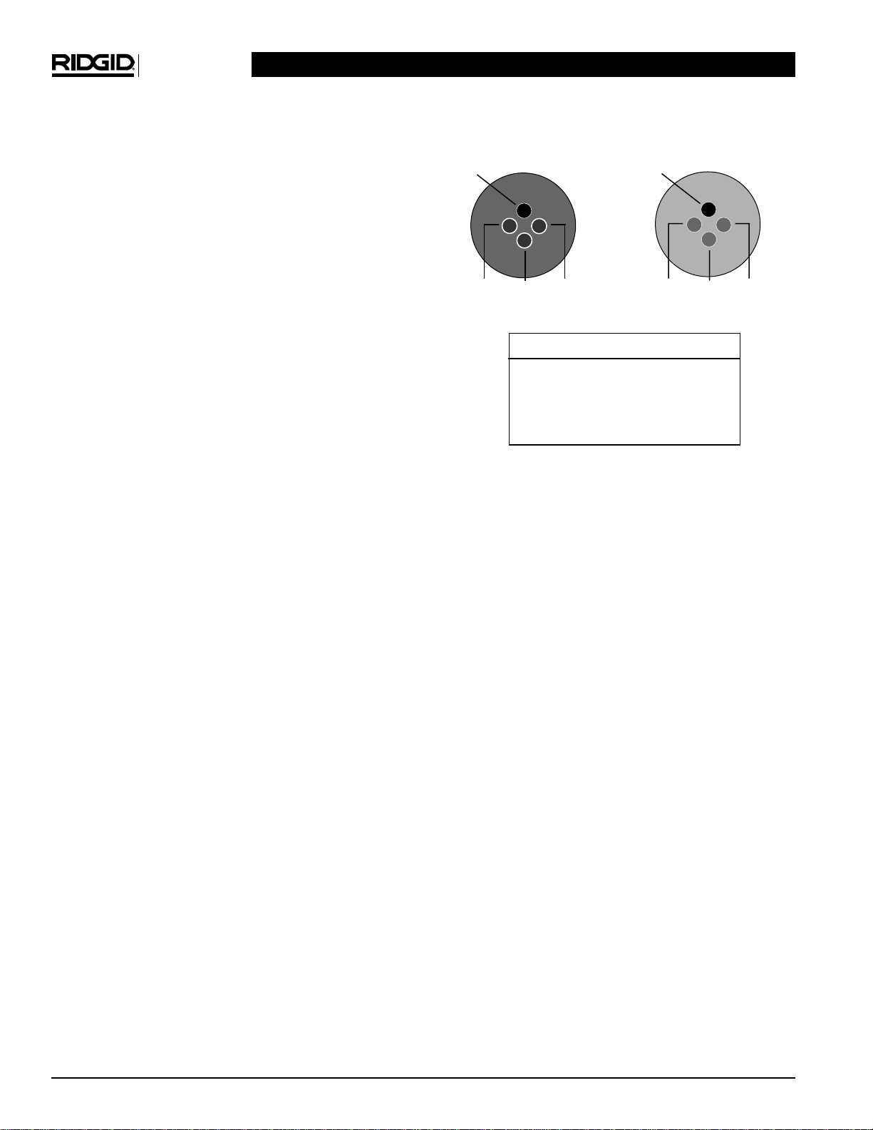
(Refer to Figures 2-10)
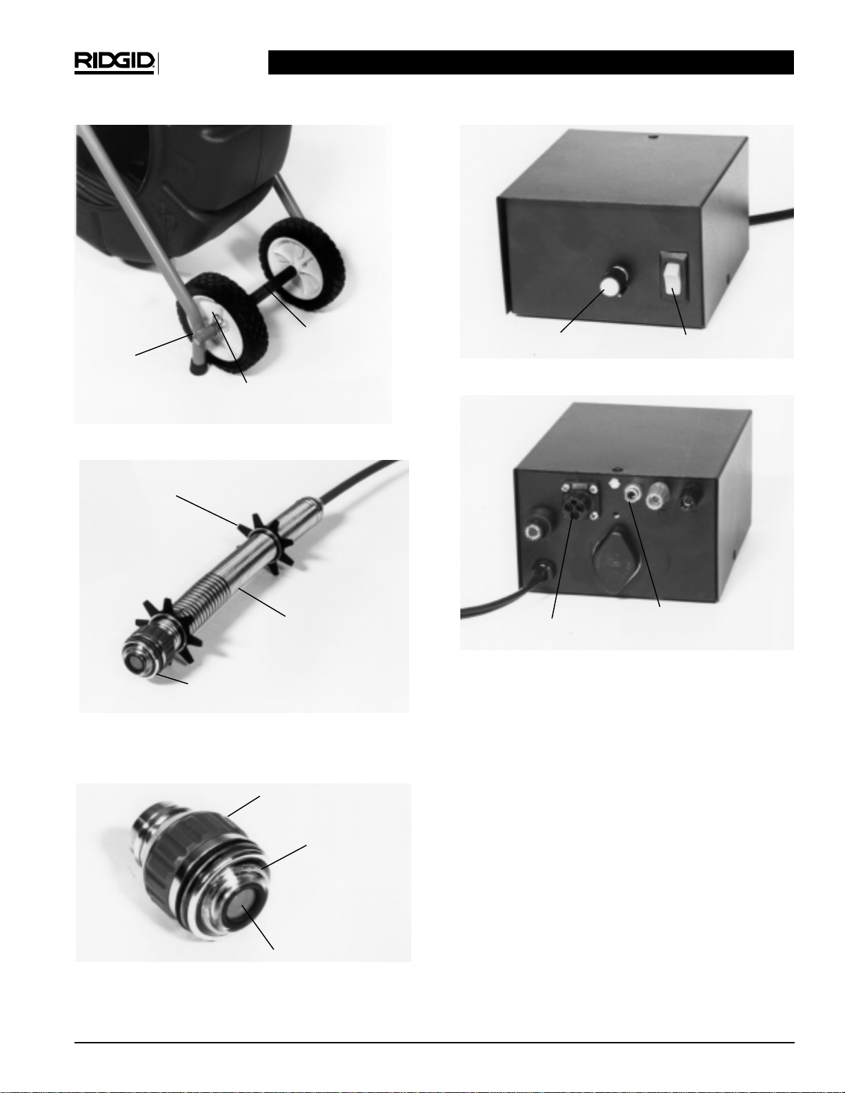
Brake Large black knob on dolly that controls the
spinning action of reel. The purpose of the brake is to
provide a slight drag on the reel to prevent freewheel-
ing, resulting in excessive cable exiting the reel. The
brake is not intended to lock the reel.
Cable Guide The U-shaped metal bar above the
brake that the camera and push cable passes through
as it exits the reel.
Camera Head Contains a video camera module,
LED board, and control and protective components for
the video system. The camera is rated to a water
depth of 330 feet.
Camera Skid The small plastic ring found on the
camera head (not to be confused with centering
guides). Its purpose is to protect the stainless steel
housing from abrasion. A metal C-clip (on the side
that faces the spring assembly) holds the camera skid
in place. The skid should be replaced as soon as it
wears down to the grooves, such that it is smooth.
Centering Guides Small, plastic, star-shaped devices
that mount onto the spring assembly using snap rings.
3″and 6″in diameter, they center the camera and help
keep it off of the bottom (out of the sludge).
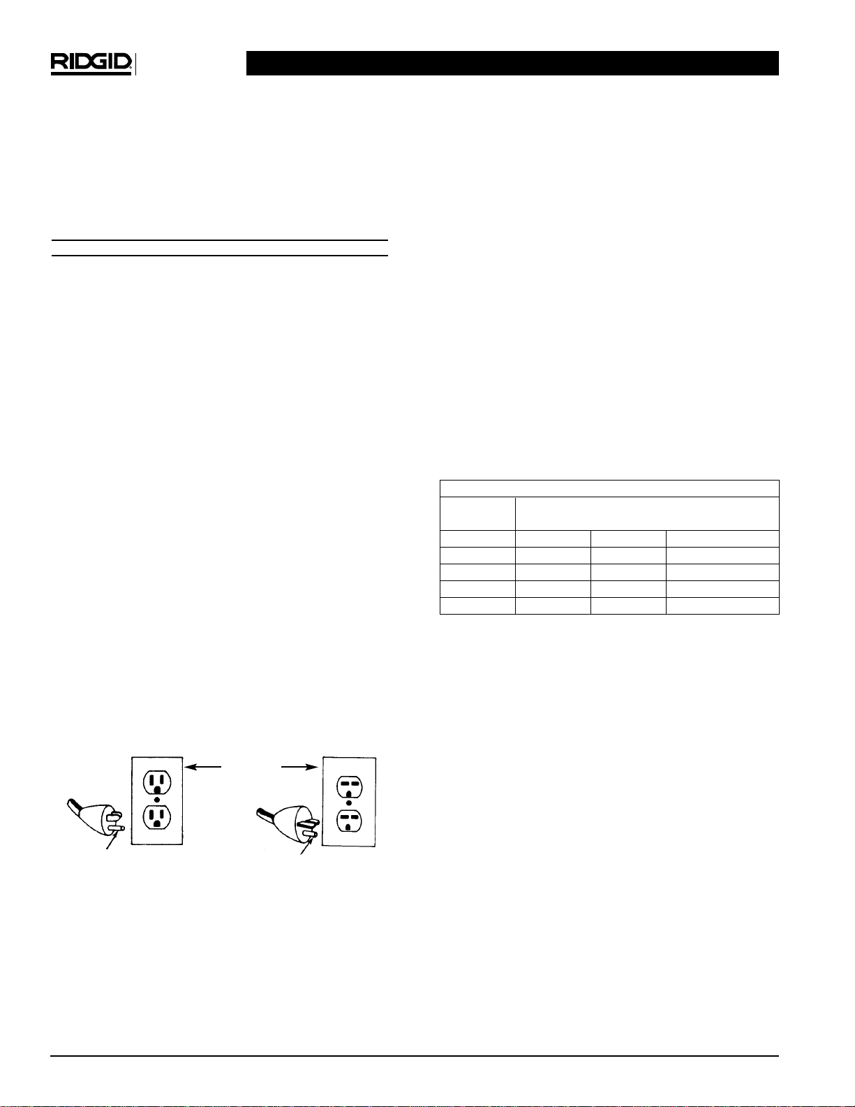
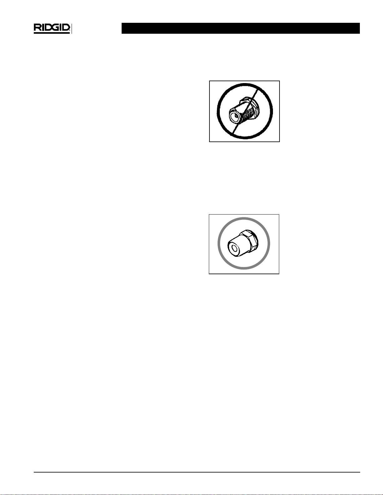
Connectors All the “plugs” in the system that con-
nect the camera; push cable; hub; interconnect cable;
monitor/power pack. These are the connectors that
have guide pins (male) and guide sockets (female).
These connectors ARE NOT to be confused with 120
volt (or 230V) AC outlet plugs, or any video/audio
jacks. Refer to Figure 1.
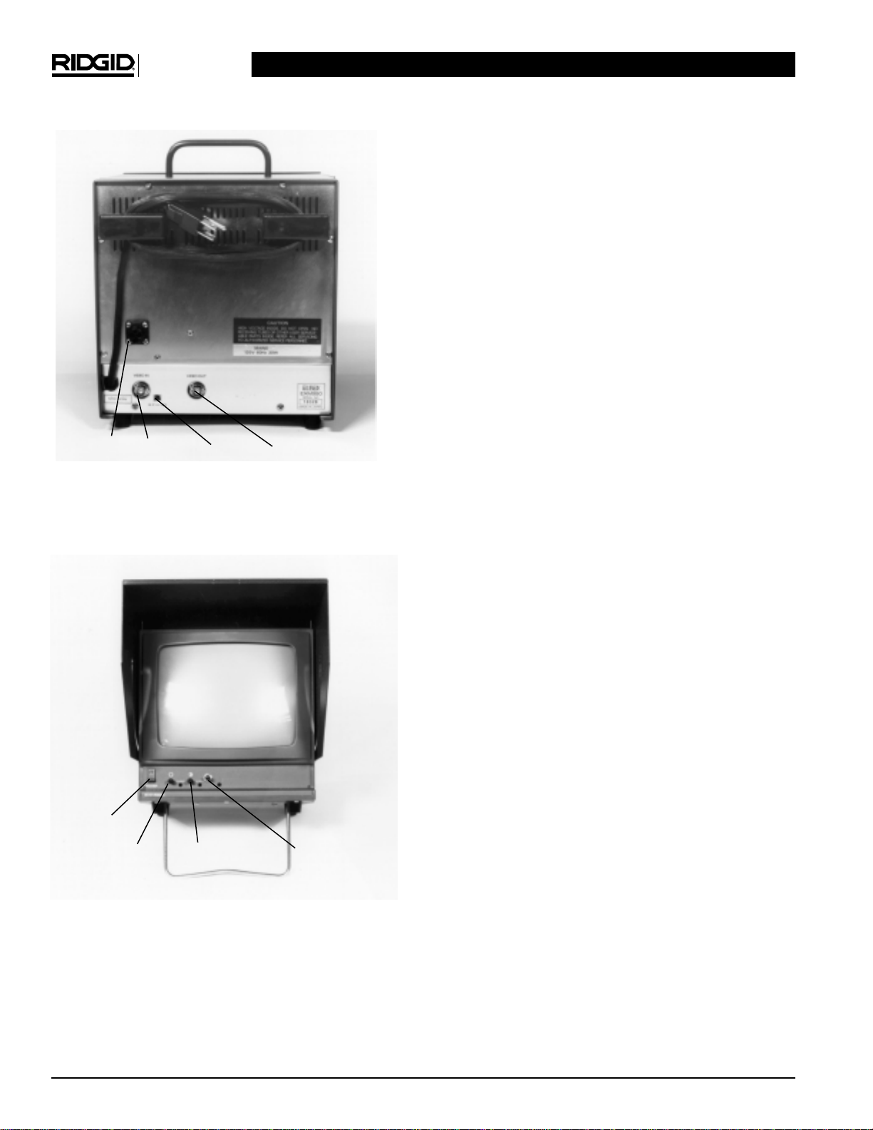
Dimmer A small knob found on the front of monitors,
and power packs. This allows control of power to the
LEDs to dim or brighten them as conditions vary in
pipe. For example, white PVC pipe may reflect too
much light to the camera, making the picture over-
exposed (too bright). Similarly, black ABS pipe will
reflect much less light, making the picture underex-
posed (too dark). Adjustment of the dimmer allows
fine control of the LED lighting for an optimum picture.
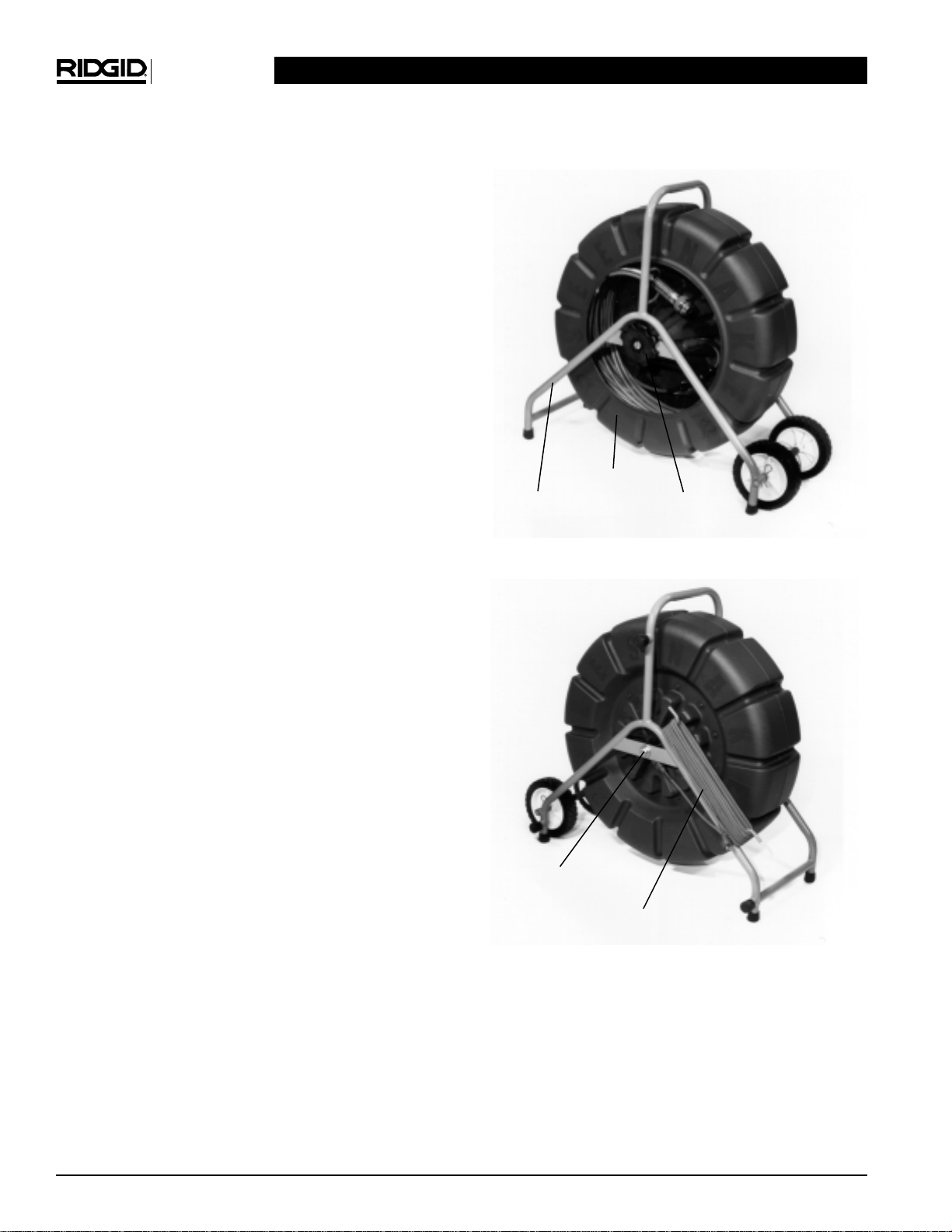
Dolly Metal frame that the reel is mounted to. The
dolly has a second set of feet on the back side of the
reel, allowing the system to rest on its side (open-end-
up) for greater stability. There are also three fittings
(with capped covers) that allow attachment of the
optional auxiliary handle.
Hub The center, cone-shaped portion of the reel.
Within the hub is the slip ring and axle.
Interconnect Cable Thirty-three foot cord that plugs
between the output of the hub and the monitor/power
pack. It is kept stored on the dolly, and left plugged
into the hub.
LED Light Emitting Diode. Solid-state light that, unlike
an incandescent lamp (a regular light bulb), does not
have a fragile filament. These give off red light to illumi-
nate pipe interiors. The camera module is especially
sensitive to red light, resulting in a higher quality picture.
LED Ring The polycarbonate (plastic), donut shaped
ring that protects the LEDs from abrasion. There is also
SeeSnake Diagnostic Equipment
Kollmann
5

SeeSnake Diagnostic Equipment
Kollmann
6
Tilt Stand Small kick stand on bottom of Monitors.
This helps raise the angle of the screen when the
a metal ring embedded around the perimeter of the
LED ring that helps extend the life of this component.
Locking Sleeve This device is found at the rear of
the camera, within the spring. It holds the connector in
place and serves as an anchor for the safety cables.
This device is unscrewed from the back of the camera
to detach the connector from it.
Monitor The “television” in the system. RIDGID/Koll-
mann monitors include the power pack within them
and have a dimmer knob to adjust the LED brightness
for varying pipe conditions. They also include a sun-
shade, tilt stand, handle, and AC cord storage hooks.
Power Pack This component is supplied with sys-
tems where a monitor is not ordered. The power pack
converts 120 volt AC (or 230V) power from a wall out-
let to ~12 volts DC power to run the camera head
(video and lights), as well as any options. Its features
include a power switch, connector (female to intercon-
nect cable), a dimmer, and a video out jack providing
a signal to your monitor.
Reel The gray plastic portion of the system that holds
the push cable and camera.
Safety Cables Stainless steel cables (two) within the
spring assembly that connect between the push cable
termination and the locking sleeve holding the con-
nector at the back of the camera head. These prevent
the spring from over-extending when pulling the cam-
era out of a pipe. Together, they provide over 800
pounds of breaking strength.
Sapphire Window The small, round port that the
camera “looks” through. This component is virtually
scratch-proof providing excellent video throughout the
life of the system.
Spanner Wrench 0ne-piece wrench used to engage
the end of the spring when removing the camera
head. To remove the camera from the spring, you
must use a spanner wrench.
Spring Assembly Flexible stainless steel spring and
associated components that hold the camera to the
push cable, provides a flexible transition from camera
to push cable, and protects the terminations within the
spring.
Sunshade This metal device is included on monitors
to protect the screen when system is not in use
(closed) and to optimize the picture in bright sunlight
(opened).
Brake
Interconnect Cable
Axle
Reel
Dolly

monitor is sitting on the ground for easier viewing.
(Figure 2-10):
Figure 2 –Reel, Front
Figure 3 –Reel, Back
Figure 4 –Wheel Set
Figure 5 –Camera/Spring
SeeSnake Diagnostic Equipment
Kollmann
7
Wheel Spacer
Spring Assembly
Camera head
Centering Guide
Axle Mount
(1 of 2) Cotter Pin
(1 of 2)
Camera Skid
LED Ring
Sapphire Window
Power Button
Dimmer (to control
LED lighting)
Connector to
Interconnect cable
Video Out Jack (use
supplied video cable
as input to monitor)

NOTE! Current models have the wheel mounted outside
the axle mount (and not as pictured above).
Figure 6 –Camera Head
Figure 7 –Power Pack –Front
Figure 8 –Power Pack –Rear
Figure 9 –Monitor Back
All RIDGID/Kollmann monitors include an integrated
power supply with connector to reel, dimmer sunshade,
tilt stand, AC cord storage hooks, and handle.
Figure 10 –Monitor Front
The sunshade on this monitor has been locked open,
and the tilt stand is engaged. Close the sun shade
whenever the monitor is not in use. Always adjust the
settings below for each inspection to ensure the opti-
mum picture.
Set Up and Operation
NOTE! The rims of the wheels are flat on one side, con-
vex on the other. To make the wheel stance as
wide as possible (more stable), the flat edge
should face outward when the wheels are
mounted.
To Install the Wheels Onto the Dolly
1. Position the axle so that the side with the rubber
foot is on the same side as the other two rubber
feet on the dolly frame. Slide one wheel onto the
axle with the flat edge facing outward.
2. Slide the axle and wheel through one frame mount
(on the side with the rubber feet), then through the
plastic spacer. Slide the axle through the other
frame mount.
3. Slide the second wheel onto the axle with the flat
edge facing outward. Slide the washer onto the
axle (outboard of the wheel); then insert the cotter
pin at the far end of the axle.
Models with Power Packs
1. Find the power button at the front of the power
pack, and make sure it is switched OFF. Plug the
power pack’s power cord into an approved outlet.
2. Unwrap the interconnect cable from its storage
hooks on the dolly. Plug the loose end of this cord
into the mating connector at the rear of the power
pack, referring to Figures 1 and 8.
NOTE! Figure 1 demonstrates the proper way to plug
connectors together. This is true in all cases.
For example, the camera head will plug directly
into the back of the monitor/power pack, using
these guidelines.
3. Locate the small video cable that came with the
power pack. Plug either end of it into the small jack
at the rear of the pack labeled video out. (These
types of connectors are called RCA jacks.) Most
likely, your monitor will have the same type of con-
nector for video in. (If not, it has a connector called
a BNC jack.)
4. Plug the remaining end of the video cable into the
rear of your monitor at the video in jack.
5. Turn the monitor ON, then the power pack. You
SeeSnake Diagnostic Equipment
Kollmann
8
Power
LED dimmer
ContrastBrightness
Video Out (to
your VCR)
HiZ-75ohm
Video In
Connector

should now have a picture on the screen. If the pic-
ture doesn’t look perfect, you can adjust the con-
trast, brightness, and horizontal/vertical hold on
your monitor, as well as the brightness of the cam-
era head LED lighting using the dimmer knob locat-
ed on the front of the power pack.
NOTE! If you do not have a picture, make sure you have
followed the above steps correctly, checking to
see that the video cable is plugged in and the
120V (or 230V) source is actually working.
Models with RIDGID/Kollmann
SeeSnake Provided Monitors
1. Gather the reel/dolly and monitor in a convenient
area near a 120V (or 230V) AC power source.
2. Unwrap the interconnect cord from its hooks located
on the back side of the dolly. Plug this cord into the
connector at the rear of the monitor, referring to
Figure 1 for the proper way to make the connection.
NOTE! Figure 1 demonstrates the proper way to plug
connectors together. This is true in all cases.
For example, the camera head will plug directly
into the back of the monitor/power pack, using
these guidelines.
3. Lift and lock open the black sunshade that covers
the screen of the monitor.
4. Plug the power cord for the monitor into a standard
120 volt outlet (or 230V).
5. Locate the power button at the lower-left, front of
the monitor and depress it. In a few moments you
should have a picture. You may need to adjust the
brightness and contrast of the monitor. This can be
accomplished by adjusting the dials to the right of
the power button. The one represented by a sun
above it is the brightness, and the one with the par-
tially-shaded circle above it is the contrast. You can
also dim or brighten the cameras lighting with the
dimmer knob, located on the lower-right, front of
the monitor.
NOTE! These adjustments will be more accurately made
when the camera is positioned in a section of
pipe. If the picture still does not look right, or
there just isn’t one, carefully review the above
steps to ensure they were properly followed.
Hooking Up VCR Systems
WRONG
These types of connec-
tors, commonly referred to
as F style and labeled
UHF/VHF, are the incor-
rect input jack at the rear
of the VCR for recording.
Trying to input a video sig-
nal through this jack will
not work. These are usual-
ly labeled UHF/VHF, and
are for cable TV or anten-
na input.
NOTE! The video cable supplied with every system will
not mate with this connector. The F-style con-
nector on your recording device may look slight-
ly different.
RIGHT
This type of connector, an
RCA (female) jack is the
correct jack for input to the
VCR. Usually, this jack will
be color-coded yellow, and
will be la-beled VIDEO IN.
NOTE! The video cable supplied with every system has
the correct mate for this connector. If your sys-
tem included a monitor, an adapter is supplied
to mate with its video out jack. power packs
have a female RCA video out jack (like shown),
for comparison.
Hooking up a VCR or Camcorder
Refer to VCR/camcorder manual for proper cable dia-
grams. To hook up the VCR/camcorder to a RIDGID/-
Kollmann SeeSnake monitor or power pack:
1. Locate the video cable that came with the system.
This cable has “male” RCA jacks on either end for
the power pack. An adapter (BNC-to-RCA) is sup-
plied to mate this cable with the video out jack on
our monitors.
2. Plug one end of the video cable into the RCA video
out jack at the rear of the power pack or twist and
lock the adapter-end onto the video out jack at the
rear of the monitor.
3. Plug the other end into the RCA-style, video in jack
for your VCR/camcorder.
SeeSnake Diagnostic Equipment
Kollmann
9
“RCA”style, Video In
“F”style, UHF/VHF

NOTE! Do not attempt to use any F-style, UHF/VHF
jacks (above left) on your recording device as
the video input jack. Use only RCA-style jacks
labeled VIDEO IN.
Recording to a VCR
Consult the manual of your VCR for the correct
channel required when using its video in jack.
Depending on the make, this may be called line a,
line b, or av1. (DO NOT assume this will be CH.
3/CH. 4.) Follow the manual for your VCR to record
video from an external source.
Recording to a Camcorder
Consult the manual of your camcorder for record-
ing from an external source (via its video in jack).
This function is usually selected with a switch, often
labeled camera/vcr.
Playing a Video Tape from a VCR/Camcorder to
the RIDGID/Kollmann SeeSnake
1. Unplug the system from the monitor to disconnect
any video signal from the camera to the monitor.
2. Hook up the video cable from the video out jack of
the recorder, to the video in jack of the monitor.
3. Follow the instructions in the VCR/camcorder man-
ual for video tape playback to a monitor.
4. DO NOT store or transport the monitor with the
adapter and/or video cable installed.
Solutions to Common Recording Problems
1. If the jack on the recording device is not an RCA
jack labeled video in, it is probably not the correct
input.
2. When making a video recording, ensure the video
cable runs from video out on the monitor, to video
in on the recording device (NOT the other way
around).
3. When reviewing a tape on the monitor, ensure the
interconnect cord from the reel to the monitor is
unplugged. If not, the image from the camera and
the tape will combine producing a noisy picture.
4. Do not run video in and video out cables from the
VCR to the monitor simultaneously. Use either
video in or video out at any one time.
Pre-Checks
Mechanical Checks
1. Check the cotter pin that holds the axle in place to
ensure it is fully engaged. The wheels should both
spin freely.
2. Rotate the reel brake to a position that allows you
to easily pull cable from the reel, yet stops immedi-
ately when you aren’t retrieving cable. For trans-
port, add more friction to the brake.
3. Grasp the spring assembly in one hand, and the
camera head in the other. Ensure the spring is
tightened ONLY to the point where the cut end of it
is as far as it can go in the camera head’s threads.
If it is undertightened, you should be able to physi-
cally screw the spring a little farther onto the cam-
era’s threads. If it is overtightened, the cut end of
the spring will “crawl” up and over the threads. If
this occurs, follow the procedures in the
“Maintenance – Removing the Camera Head” sec-
tion to properly seat the spring using the spanner
wrench provided.
4. Check to see that the connector at the end of the
push cable is fully seated into the connector
attached to the cone-shaped portion of the hub
(inside the reel). Likewise, check that the
Interconnect cable is completely plugged into the
hub. Periodically inspect these connectors for good
connections as the system is used.
Electrical Checks
The system should always produce a crisp picture
that is free of noise and lines. Sometimes, especially
during cold-weather conditions, it can take a moment
for the system to heat up before it will produce the
optimum picture. Otherwise, check that connectors
are fully engaged and follow these guidelines:
1. With the system energized, look to see that an
even amount of light is coming from the LEDs.
Place the camera in the reel, and give it a good
spin while watching your monitor.
2. At the rear of the RIDGID/Kollmann monitor a small
switch can be found below and to the right of the
video in jack. It has two settings: 75 ohm and High
Z. For almost every application, the switch should
be set in 75 Ohm position. Sometimes when using
a VCR with the system, the High Z position is
required. Refer to your VCR manual to select the
correct position.
3. Find a section of pipe that is 2-6 inches in diame-
ter. Roll a page of newspaper or business station-
SeeSnake Diagnostic Equipment
Kollmann
10
Test Equipment Depot - 800.517.8431 - 99 Washington Street Melrose, MA 02176 - TestEquipmentDepot.com

ary into the pipe and watch the monitor. The picture
should be clear and the lighting should be even on
the pipe walls. Try adjusting the contrast and
brightness, as well as the lighting (using the dim-
mer knob on the monitor/power pack) to obtain the
best picture. Remember, as the materials of pipe
vary, it will be necessary to adjust these settings to
maximize picture quality on different jobs. For
example, white PVC pipe requires less lighting than
Black ABS. As experience is gained with the sys-
tem, operators will learn that slight adjustments in
these settings can highlight problems within a pipe.
At the Job Site
1. The camera can almost always be pushed far-
ther when grip-style rubber gloves are worn. It
is much easier to get a grip on dirty push cable,
and the gloves also keep sludge off the hands.
2. Properly positioning the equipment before you
begin an inspection will save time, be more
comfortable, and minimize the potential for
equipment damage. Set the monitor in an area
where it is unlikely to fall, and where it can be
viewed while you are pushing the camera. A
good location is right next to the cleanout or entry
point. Be sure to keep it from getting wet.
3. Set the reel about 6 to 8 feet from the entry. This
will provide ample cable to grasp and develop
momentum without having a lot of slack dragging
on the ground. Slack can be alleviated by putting
friction on the reel using the brake. If it is set cor-
rectly, push cable will only come off the reel when
you pull on it.
4. Always try to run water down the pipe undergo-
ing inspection. This will keep the system much
cleaner, and allow you to push noticeably farther
with less friction. This can be accomplished by
feeding a hose with a small amount of flow into the
entry or occasionally flushing a toilet that drains to
the pipe. If the water is preventing you from seeing
an area of importance, temporarily turn it OFF.
5. When pushing, the end of your stroke should
be as close to the entry as possible. Standing
too far back, with an excess of cable between your
hands and the entry may cause the cable to fold on
itself outside the entry.
6. Folding the push cable on the sharp edge of an
entry can cause it to snap. Extreme caution
must be used to minimize the chance of bend-
ing the push cable on sharp corners. This is a
common cause of push cable failure, and all opera-
tors should be aware of this. If the camera just
doesn’t seem to want to go any farther, DON’T
FORCE IT! If another entry is available, try it.
7. When inspecting a pipe, it is usually necessary to
give a little extra push in the bends. Back up, if nec-
essary, and “pop” the camera through a turn using
the least amount of force required. Try to be as
gentle as possible, and don’t hammer or snap the
camera head through corners. After some practice,
you may learn that the best way to inspect a sec-
tion of pipe is to push the camera through quickly,
then draw the camera back home slowly and even-
ly. It is always easier to control the camera when
pulling than when pushing.
8. Make sure the sapphire window is clean prior to
entry. Some users claim that a slight film of deter-
gent on the lens minimizes the possibility of grease
sticking to the port. In any case, take advantage of
any standing water in the pipe to wash the front of
the camera by jiggling it in the water. Flushing the
pipe with water supplied by a hose or periodically
flushing a toilet can help keep the port clean and
improve performance by reducing cable friction.
9. Take advantage of the lighting to keep track of
where the camera is headed. If the particular pipe
you are inspecting is easier to evaluate with other
than the maximum lighting, periodically maximize
the lighting (using the dimmer knob on the moni-
tor/power pack) to get a look at what lies ahead. Be
aware of any obstructions, such as a crushed sec-
tion of pipe or excessive hard build-up, that may
prevent retrieval of the camera. do not clear
clogged lines with the camera head!
9. Pipe materials and conditions vary. Adjustment of
the contrast and brightness settings, as well as the
light dimmer after the camera is within the pipe,
can greatly increase picture quality. This is particu-
larly important when your customer is supervising,
and when making recordings.
10. Whenever possible, lay the system on its side feet
for even greater stability. This is also preferred when
on a rooftop (entry through a roof vent) or hillside.
11. If local 120V (or 230V) AC power for monitor is not
available, you can operate the system using a volt-
age converter that plugs into your vehicle’s
cigarette lighter. They convert your vehicles 12 volt
DC to 120 volts (or 230V) AC. As long as you are
not rewinding and fast-forwarding video tapes fre-
quently, this method of powering the system can be
done safely on a good battery for several hours.
SeeSnake Diagnostic Equipment
Kollmann
11

12. The system can travel through multiple 45 and 90
degree bends and wyes. Do not, however, try to
force it through a P-trap or T if there is a large
amount of resistance.
13. Do not attempt to remove or store push cable on
the reel solely by turning the reel itself. Release the
brake enough so that you can manually push or
pull cable from the reel and wind or unwind it.
14. Be careful in T-entries not to fold the camera back
on itself, this could cause camera to stick.
NOTE! Some customers have reported success in con-
trolling camera entry into hard Ts using a “shoe
horn”made from a length of 1-inch copper pipe
of the necessary length to reach the T that has
been flattened and curved at the end. With this
device, you can position the curved portion into
the side of the T where entry is preferred and
guide the camera in the proper direction.
Maintenance
Preventative Maintenance
Camera Head
1. The camera head requires little maintenance, other
than keeping the LED ring and sapphire window
clean. Use a soft nylon brush, mild detergent, and
rags and sponges from the camera head up to (but
not including) the monitor/power pack.
2. When cleaning the camera, do not use scraping
tools as they may permanently scratch these areas.
NEVER USE SOLVENTS to clean any part of the sys-
tem. Substances like acetone and other harsh
chemicals can cause cracking and crazing of the
LED ring, which could affect waterproofing.
3. As you use the system more and more, you may
be surprised to find that scratches on the LED ring
will have a minimal effect on the performance of the
lighting. Don’t sand the LED ring to remove
scratches, as it is part of the watertight housing.
4. Another good way to extend the life of the camera
is to avoid removing obstructions from pipe with the
camera head.
Spring Assembly
1. The spring assembly is the area where foreign mat-
ter is most likely to accumulate. Within the spring is
the splice between the push cable and a connector
(and maybe a sonde unit for a pipe location sys-
tem). Should sharp objects or harsh chemicals be
allowed to remain in this area for long periods, they
may wear on these components. Stretch the spring
end-to-end as far as the internal safety cables
allow to check this area. Stretch again and stir in a
bucket of warm water and mild detergent to flush
this area.
Push Cable, Reel/Dolly
1. The push cable and reel/dolly require almost no
maintenance. (Of course, a clean system will last
longer and be more impressive to your customers.)
It is important, however, to keep the push cable
clean to spot any excessive cuts or abrasions,
while making it much easier to grasp and push.
NOTE! Whenever you are retrieving push cable into the
reel, an excellent way to cut down on cable
grime is to run it through a rag in the last hand
that touches the cable as it enters the reel. For
an overhaul cleaning, lay the system on its side
feet and fill the reel with lukewarm water and a
mild detergent. Leave it overnight and spin it
occasionally. Remove the water prior to use and
run a rag over the cable.
Monitor/Power Pack
1. The monitor/power pack requires a little more care.
The same is true for any monitor in the field. Unlike
the rest of the system, the monitor/power pack
aren’t waterproof. Clean them with a damp cloth,
and ensure foreign matter does not get into any
cooling vents. Always avoid dropping or shocking
these components.
Corrective Maintenance
Removing Camera Head
The system has been designed so that the camera
head can be removed for troubleshooting, installing
the transmitter, or to use in a different application on a
separate cable.
1. Pay out enough cable to place the camera and
spring assembly on a work bench or other conve-
nient work area. Set the brake to prevent the reel
from spinning.
2. Locate the metal spanner wrench that was provid-
ed with the system and hook the cut end of the
spring (directly behind the camera head) with the
business end of the spanner and turn the camera
off the spring (Figure 11). The camera should now
be hanging by its locking sleeve and safety cables
(Figure 12).
3. Grasp the ribbed portion of the sleeve with one
hand and the camera and cables with the other.
Rotate the ribbed portion of the sleeve (counter-
SeeSnake Diagnostic Equipment
Kollmann
12

clockwise when camera is viewed from the rear) to
unscrew it from the camera. If it is difficult to turn,
get it started with a pair of pliers (Figure 13).
4. When the sleeve is completely unscrewed, slide it
down the black cord so that the actual connector is
exposed. Grasp the connector in one hand and pull
it straight out of the back of the camera. Wiggling
the connector slightly, side-to-side, may help break
it free (Figure 14).
Figure 11
The spanner wrench is hooked into the end of the
spring. The camera is then rotated (counter-clockwise
when viewed from front) with the other hand.
Figure 12
Once the camera head is removed from the spring,
the locking sleeve can be seen holding the connector
to the back of the camera. The safety cables are
mounted to a rotating portion of the sleeve, which
helps prevent their twisting.
Figure 13
The locking sleeve has been removed by the camera
back by rotating it counter-clockwise (when viewing
the camera from the back). The connector is now all
that holds the camera on.
Figure 14
The camera head is now removed. Note that these
connectors are the same style as those found through-
out the system.
Locating Faulted Components
The basic idea in troubleshooting the system is to use
the camera head to eliminate suspected components.
Here are the areas we will try to isolate the fault to:
camera head, reel/dolly, interconnect cord, monitor/-
power pack. As a scenario, we will assume that the
symptom is no video, no lights.
1. Remove the camera from the spring assembly.
2. With the monitor/power pack set up for operation,
plug the camera head directly into the back of the
monitor/power pack where the interconnect cable
is usually connected. Turn on the system and
check the monitor for a picture. If there is a good
picture with proper lighting, the problem is some-
where between the interconnect cable and the
spring assembly. Proceed to step 4. If there is no
picture, the problem is probably in the camera head
or monitor/power pack.
3. To virtually eliminate the monitor, play a tape on
your monitor with a VCR through the video in jack
at the rear (VCR – video out; monitor – video in). If
you get a good picture, it is almost certain the prob-
lem is in the camera head. The power pack is a lit-
tle more complicated to troubleshoot, so contact
Ridge Tool Company if you suspect it is faulted.
4. Plug the interconnect cable into the monitor/power-
pack. Unplug the other end of the interconnect
cable from where it plugs into the reel-hub, and
plug the camera head into this end. Turn on the
system and check the monitor. If you get the video
and lights back, the problem is likely in the push
cable or hub. If there is no picture, the interconnect
cable is the likely fault.
5. Once you suspect a component, contact Ridge Tool
Company Technical Services. We will establish a
plan of action to get your system back on line.
SeeSnake Diagnostic Equipment
Kollmann
13

6. For additional troubleshooting suggestions, please
refer to Chart 1.
Re-Installing Camera Head
1. Lay out enough cable to lay the spring assembly on
a convenient work area and set the brake.
2. Plug the connector at the spring assembly into the
camera head, making sure that the guide pins/sock-
ets are aligned.
3. Grasp the camera head and safety cables with one
hand and turn the ribbed portion of the locking
sleeve to screw it into the back of the camera.
IMPORTANT: Try not to twist the cord or the camera,
only the locking sleeve. If this is done
properly, the cord and safety cables will
not be twisted around each other when
you view them from between the windings
of the spring.
4. Once the locking sleeve is tight into the back of the
camera, thread the spring onto the camera and,
using only your hands, screw the camera onto the
spring.
NOTE! The camera head will be properly mounted when
the end of the spring is snug between the cam-
era and the thread (not so far that it begins to
raise off the threads) and you cannot manually
unscrew the camera.
Transportation & Storage
1. Slip the camera into the reel with the rest of the push
cable. Turn the brake clockwise enough so that the
reel does not rotate unless you manually turn it.
2. Unplug the interconnect cable from the moni-
tor/power pack and wrap it loosely onto its storage
hooks located on the dolly.
3. If space allows, the reel/dolly should be laid on its
side during transportation and use. You will notice
that there is a second set of feet (three) on the side
of the reel where the interconnect cable is stored. If
there is not enough space to lay the system on its
side, stand it up and run a strap or cord through the
dolly and secure it to the vehicle.
4. Close the sunshade over the screen of the monitor
and wrap its outlet cord onto the hooks provided at
the rear.
5. Keep spare parts, tools, and the manual secure in
a work bag to protect them when not in use.
6. When possible, keep the system stored in a cool,
safe place. Leaving the camera pointed into the
sun or a high powered light source (when operat-
ing) can damage the imaging chip.
Options
Centering Guides: 3″and 6″
The centering guides are designed to help center the
camera in various sized pipes, and also help keep the
camera out of the bottom sludge. Picture quality is
improved as they help position the camera towards
the middle of the pipe. This allows the camera to see
an equal amount of the pipe wall in all directions.
Do not assume that the guides are only helpful in 3″
and 6″pipe! They also help in larger pipe by bringing
the camera closer to center and raising the camera
out of the sludge that is often found below the water
line. Keeping the camera off the bottom of the pipe
keeps the front of the camera cleaner, longer.
It is recommended that guides be used whenever pos-
sible (3″and up) as they protect the system from wear
and tear. However, if you are having trouble going fur-
ther in a particular pipe, try it without the guides. The
best advice is to experiment with local conditions and
decide what is best for the given job. One way to
increase their flexibility is to pre-strain them by bend-
ing the spikes back and forth a few times before use.
To install the guides, wind two metal snap rings per
guide into the push cable just like you would slip a key
onto a key ring. You should usually use 3 guides.
Position each guide where you want it on the spring,
with one of snap rings on either side. Look for grooves
on either side of the spikes on the guide and wind a
snap ring into each groove to lock it onto the spring.
When it is time to remove them, lift the edge of the
snap rings out of the grooves with the tip of a small
screwdriver and unwind them from the grooves. Slip
the snap rings off the spring/push cable and store
them with the guides for later use.
Pipe Location Transmitter
The pipe location transmitter allows the user to pin-
point the location and depth of the camera head
greater than 10 feet underground in cast iron pipe.
The transmitter emits a 512Hz signal that is sensed by
the receiver. The transmitter is designed to work with
manufacturer’s receivers who use 512Hz.
One of the great features of our transmitter is that it is
powered by the same power supplied to the camera
head. Once installed, it is always ready for use,
SeeSnake Diagnostic Equipment
Kollmann
14

whether or not you choose to bring the receiver along
on the job. There are no batteries or extra cables
required, and the system still travels the hard 90
degree bends.
Installing the Pipe Location Transmitter
1. Remove the camera head from the spring assem-
bly. (See Corrective Maintenance – Removing
Camera Head section.)
2. With the camera head removed, you can see that
the connector passes through the locking sleeve,
and that there is a rounded ridge on the connector
that prevents it from slipping out the rear of the lock-
ing sleeve. You want to carefully push the connec-
tor out the back of the locking sleeve (Figure 15).
Use a blunt object, such as the eraser-end of a pen-
cil or a finger to push on it, while pulling on it from
the back. Don’t grasp the coil cord when pulling,
grasp the connector! You can lube the connector to
make it easier, if necessary. be careful not to dam-
age the sockets of the connector by pushing on it
with a sharp object, like a screwdriver.
CAUTION
Be sure to use non-conductive lubricant. a sili-
cone lubricant is suggested.
Figure 15
After removing the camera head, slip the coil connec-
tor out of its locking sleeve. Some silicone lubricant
makes removal much easier. Keep the stainless
cables untwisted by holding the sleeve and rotating
the ring on it that the cables are attached to.
Figure 16
On the transmitter, unscrew the plastic locking sleeve.
Place the plastic locking sleeve (leading with the
tapered end) over the coil connector. Again, some sili-
cone lubricant makes this easier.
Figure 17
Push the coil connector onto the leads making sure
that it is fully seated. Screw the plastic locking sleeve
back onto the transmitter.
Figure 18
When completed, grasp both ends of the spring
assembly and stretch it to draw the transmitter inside.
Check that the coil cord and stainless cables are situ-
ated properly. Push the camera-end of the transmitter
back through the locking sleeve using some silicone
lubricant, if necessary. Re-install the camera head.
SeeSnake Diagnostic Equipment
Kollmann
15

3. On the transmitter, unscrew the plastic locking
sleeve. Place the plastic locking sleeve (leading
with the tapered end) over the coil connector
(Figure 16). Again lubricant makes this easier.
4. Plug the coil cord connector into the rear of the
transmitter, making sure that it is fully seated.
Screw the plastic locking sleeve back onto the
transmitter (Figure 17).
5. Carefully insert the transmitter into the spring
assembly ensuring that no cabling gets bent or
wedged between the transmitter and the spring
assembly. You can stretch the spring assembly,
end-to-end, to help draw the transmitter into it.
6. Push the female connector of the transmitter
through the metal locking sleeve (Figure 18). Use
some silicone lubricant on the exterior of the con-
nector, if necessary.
7. The system should now look like it did when you
first removed the camera head, except the trans-
mitter is within the spring assembly. Re-install the
camera head. (See Re-Installing Camera Head
section.)
8. Refer to the manual provided along with your
receiver for operation of the location equipment.
Auxiliary Handle
The auxiliary handle attaches to the three fittings on
the frame that are covered by plastic covers. This
handle greatly improves the stability of the system
when rolling, particularly for taller operators.
To install the handle, insert the auxiliary handle fittings
into their respective mounts on the frame, and lock into
place using three sets of bolts/crown nuts supplied.
SeeSnake Diagnostic Equipment
Kollmann
16
PROBLEM PROBABLE FAULT LOCATION
Garbled or jumbled
video
Lights, but no video
No video, no lights
Video, but no lights
White screen
Noisy picture –vertical
stripes on monitor screen
Chart 1 Troubleshooting
Horizontal or Vertical hold need adjustment
75 Ohm-High Z switch in opposite position
Fault within camera, cables , or monitor/power supply
Try to plug back from VCR into monitor with Interconnect cord plugged into monitor
Brightness turned down
Contrast or Brightness improperly set
Break in video carrying conductor (pin/socket #3) between monitor and camera
Fault within camera or monitor/power pack
Monitor/power pack not turned on
Interconnect cable not fully plugged in, or loose connection in system
Fault in any sub-assembly
Dimmer turned down
Fault within camera head, LED section
Camera exposed to excessive light
Contrast/Brightness improperly set
Camera head overheated
Visit us at www.TestEquipmentDepot.com
Test Equipment Depot - 800.517.8431 - 99 Washington Street Melrose, MA 02176 - TestEquipmentDepot.com
This manual suits for next models
5
Table of contents
Other Ridgid Kollmann Diagnostic Equipment manuals