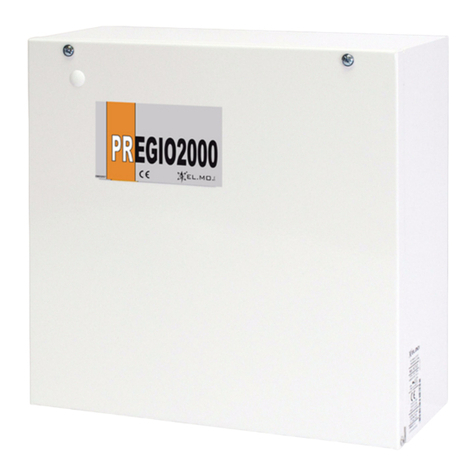
Elmo PREGIO500 User manual

1
USER MANUAL
PREGIO500
Multi-functional hybrid control unit
for intrusion detection systems
PREGIO500 is a multi-functional hybrid control unit that
supports both wired and wireless devices.
PREGIO500 is compatible with all EL.MO. serial devi-
ces (keypad, readers, power supply units, fog sensors,
concentrators and detectors) thanks to the ULTRABUS
interface.
The unit is also compatible with NG-TRX wireless tech-
nology through GATEWAY2K device over serial line.
Optional modules installable to improve unit operating
mode:
• MDWIFIH to connect the unit to a Wi-Fi network.
• MDGSMI to connect the unit to the GSM/GPRS net-
work via an internal antenna.
• MDPSTN to connect the unit to analogue phone li-
nes.
• MDVOICE64, that is a voice synthesis module that al-
lows to register up to 64 customized voice messages.
It is also possible to connect the unit to e-Connect mo-
dule via GPRS or Wi-Fi with the installation of MDGSMI
or MDWIFIH modules respectively.
PREGIO500 can manage:
• zones: 8 on-board zones, expandable up to 16 with
split function. It can manage a total of 24 zones using
concentrators.
• outputs: up to 24 outputs using concentrators and
optional relay modules.
• users: up to 32 users.
• control devices: up to 16 control devices (keypads,
proximity key readers) connected to a serial line.
PREGIO500 is supplied within a plastic case protected
against the opening of the cover and removal from wall.
Icons used in this manual:
Example
Fri01/09/17 9:00
Area 1
Messages on keypad display
Contents structure:
1. Control device description: keypad
¬Keypad indications
¬Operating mode with keypad
2. Control device description: proximity key
¬Reader indications
¬Operating mode with proximity keys
3. Control device description: remote control
¬Remote control indications
¬Operating mode with remote control
4. Phone communications
¬Phone calls reception
¬SMS texts sending and reception
5. Temperature monitoring
6. e-Connect usage
7. Maximum security
¬Maximun security property
¬Arming with maximum security
8. Remote control and interrogation
9. Anomalies diagnostics

2
.KEYPADS USAGE
PREGIO control units are multi-area devices capable of
managing up to 16 sectors.
During unit installation, sectors can be divided into:
• 4 areas with 4 sectors each;
• 2 areas with 8 sectors each;
• 1 area with all the 16 sectors.
Keypads allow to perform arming and disarming opera-
tions considering such distribution.
12
3
4
1. Number and control keys
2. Sector keys
3. Proximity keys reader
4. LED indicators
.
..Sector keys
Keypads are equipped with 4 sector keys allowing
the selection of sectors to be armed/disarmed.
Sector keys indications may vary according to the distri-
bution of sectors among areas.
4 Areas / 4 sectors mode
With 4 areas/4 sectors mode, each sector key is asso-
ciated to a sector of the currently operating area in a
univocal way; the sector keys provide information about
arming status of the corresponding sector (key S1 for
sector 1, key S2 for sector 2, etc.)
Key status
Definition
O
Sector disarmed
On
Sector armed
Fast blinking Armed with maximum se-
curity
Slow blinking Exit time in progress
8/16 Sectors per area mode
With 8/16 sectors per area mode, each sector key is as-
sociated to sector groups (during unit configuration):
each sector key provides information about arming sta-
tus of the corresponding sectors.
Key status
Definition
O
All sectors associated to the
key are disarmed
On
All sectors associated to the
key are armed
Fast blinking
All sectors associated to the
key are armed with maxi-
mum security
Fast blinking alternate to
steady light
At least one sector (but not
all sectors) associated to
the key is armed
Slow blinking Exit time in progress
Note: Once the system has been armed, arming sta-
tus is normally displayed on keypad display
and/or sector keys: such keys will remain ON
if sectors are armed. When the option Hide Ar-
ming Status is enabled in BrowserOne applica-
tion, all indications will be disabled and sector
keys will remain OFF also when the system is
armed.
If the keypad is configured as “system keypad”, its sec-
tor keys will indicate arming status of one area (and not
that of sectors.)
..Number and control keys
Keypads feature number keys and also the following
keys:
OK To enter a menu/submenu or confirm an ope-
ration.
STOP To exit a menu/submenu.
To browse among menu pages and options.
The keypads are normally equipped with a pro-
ximity keys reader.
..LED indicators
Four LEDs indicates the status of the current area. If the
keypad has been configured as “system keypad”, LEDs
will indicate system global status.

3
C
GREEN
It indicates arming status (“zones status” LED):
• ON: no zones with alarm/tamper alarm
events. The unit can be armed.
• OFF: at least one zone not assigned to the
exit path is alarmed.
• Blinking: the unit is armed and at least one
zone assigned to the exit path signals an
anomaly event; or at least one zone signals
alarm/tamper event but generates an event
dierent from intrusion alarm.
Note: when the LED is o or blinking, the
alarmed zones can be displayed
using
key.
L
YELLOW
It indicates anomaly status:
• ON: no anomalies. However, it is possible to
configure the LED so as it remains o when
there are no anomalies (via BrowserOne).
• Blinking: system anomaly (Mains failure,
Low battery, open Tamper or memory ano-
maly, etc.) or zones anomaly. For details on
how to display anomalies, please see “1.3.2
Anomalies status” on page 4.
To reset anomaly memories, arm and disarm
the unit.
%
RED
It indicates general alarm status:
• OFF: no alarm events.
• ON: alarm in progress (active relay).
• Blinking: alarm memories. To reset alarm
memories, arm and disarm the unit.
"
RED
It indicates tampering:
• OFF: no tampering zones.
• ON: tamper alarm in progress (active relay).
• Blinking: tamper alarm memories. To reset
alarm memories, arm and disarm the unit.
4 LEDs blinking simultaneously: configuration from
keypad in progress or system locked for maintenance.
Note: Once the system has been armed, if the option
Visualization protection is enabled in Brow-
serOne application, all status indications from
LEDs will be disabled.
.I
Each keypad can control one (or more) pertaining
area(s) and can display its status. The display will show
details of all areas, one by one.
The idle display shows current date and time in the above
row, and the welcome message (if it is the case) on the
row below:
Fri01/09/17 09:00
To activate the display, press any keys. It will show the
presenting area as defined during keypad installation.
The keypad shows presenting area again one minute
after the last button has been pressed.
Display with 4 areas / 4 sectors mode:
Fri01/09/17 09:00
Area 1
Display with 2 areas / 8 sectors mode:
Fri01/09/17 09:00
Area 1: --------
Display with
1 area / 16 sectors mode:
Fri01/09/17 09:00
----------------
..User code and keypad locked
It is necessary to key in a user code for the most part of
operations from keypad.
If during installation the option Enable keypad locking
for error code has been enabled, the keypad will be
blocked after the wrong code has been entered for th-
ree times and the following message will be displayed
for 90 seconds:
TEMPORARY
DISABLEMENT
During unit setup, it is possible to enable more options
to associate the generation of a tamper event to other
wrong codes.

4
..Change of current operating area
To change the current operating area, please follow be-
low steps:
- with keypad in idle mode press OK: the above row
shows user’s pertaining areas, below row shows the
currently operating area:
- press the number key (1, 2, 3 or 4) corresponding to
the desired area (such area can be accessed only if
the user has sectors authorized for the area);
- press OK to confirm, Stop to exit.
Once the operating area has been changed, LEDs will
indicate status of the area set and not that of presenting
area.
..User Menu
To enter user menu, key in user code followed by *
(asterisk). User menu includes options that can be used
for basic maintenance:
BYPASS ZONES
INSTALLER AUTH.
OUTPUT CONTROL
MANAGE SIM BAL.
CLOCK SETUP
CLOCK CALIBR.
WEEKLY PROGRAMMER
MANAGE USERS
PHONE NUMBERS
CHANGE CODE
SYSTEM TEST
MANAGE CHIME
EVENTS LOG
Maintenance
For more details, please see “1.6 User menu access
from keypad” on page 8.
.S
Once an operating area has been selected, it is possible
to enter “status display” menu: information about such
area will be displayed.
- Press arrow keys ( - ) while the interface is in
idle mode to go to status display menu pages. If Vi-
sualization protection option is enabled (EN50131
standard compliance), the user will have to enter user
code and then use arrow keys to go to status display
menu pages.
- Four options available: ZONES STATUS, ANOMALIES
STATUS, ALM/TAMP MEMORY, GSM STATUS.
ZONES STATUS
(Up Down Ok Stop)
- Press OK to enter a menu/submenu, Stop to exit.
-To browse menu pages and options, use arrow keys
( - ).
..Zones status
- Go to ZONES STATUS.
- Press OK to enter the menu.
- Use arrow keys ( - ) to browse the reports.
If there are no reports on the page, the following messa-
ge will be displayed:
No Alarms
(Stop)
Example of zone alarmed message:
ALARM
Zone 1
..Anomalies status
When an anomaly event occurs, the yellow LED Lstarts
blinking and the event can be verified from this menu.
- Go to ANOMALIES STATUS.
- Press OK to enter the menu.
- Use arrow keys ( - ) to browse the reports. If
there is more than one report, an arrow will appear
on the top right corner of the display.
Examples of anomaly reports displays:
ANOMALY
Low Battery
KEYP/RD TAMPER
Keyp/Rd 1
A1 A2 A3 A4
Area1

5
For some of the most common anomalies, please see
“9. DIAGNOSTICS” on page 21.
..Tamper/alarm memories status
This menu allows to verify alarm and tamper memories
logged on unit historic file.
- Go to ALM/TAMP MEMORY.
- Press OK to enter the menu..
- Use arrow keys ( - ) to browse the reports..
Example of a memory displayed:
KEYP/RD TAMPER
Keyp/Rd 1
..SIM Balance status
If the unit is equipped with MDGSMI module with pre-
paid SIM card, this menu allows to verify the SIM balan-
ce.
- Go to GSM STATUS.
- Press OK to enter the menu.
Above row shows the provider and the signal strength
[####], below row the card balance.
TIM [####]
???
Note: The card balance is displayed only in case of
prepaid cards; if this is not the case, the balan-
ce will not be displayed.
.A
..Simple arming
With simple arming, the sectors proposed to the user
will be armed. The sectors proposed are set during sy-
stem installation.
- Key in user code then press OK. Keys of sectors pro-
posed for arming for a specific user will blink in the
currently operating area.
- Press OK to start arming, Stop to cancel arming.
- If exit time has been set, it will be marked by beep
sounds: leave the protected areas within the set time
walking through the path set.
- At the end of exit time, sectors proposed will be ar-
med (sector keys remains lighted unless the option
Hide Arming Status is enabled).
..System arming with sectors selection -
areas sectors mode
This is an advanced arming procedure that allows the
manual selection of sectors to be armed among the sec-
tors proposed to the user.
With 4 areas / 4 sectors mode, each sector key is asso-
ciated to a sector in a univocal way.
- Key in user code then press OK to enter pre-arming
mode.
- Keys of sectors proposed for arming for a specific
user will blink in the currently operating area.
Area1
SECTORS SELECTION
- Press a sector key (S1, S2, S3, S4) to change the sec-
tors proposed (if authorized for the user).
Note: the interval between the pressure of one key
and the following one must not be over 5 se-
conds otherwise the system will arm.
Example: sectors initially proposed S1 and S3,
S1 S3 S4S2
if you press sector key S2 (if authorized) it will
become a “sector proposed”:
S1 S3 S4S2
If you press S2 key again, sector 2 will be re-
moved from proposed sectors.
- To move to another area, use arrow keys (- )
then select sectors to be armed.
- When finished, press OK to start arming, Stop to can-
cel arming.

6
- If exit time has been set, it will be marked by beep
sounds: leave the protected areas within the set time
walking through the path set.
- At the end of exit time, sectors proposed will be ar-
med (sector keys remain lighted unless the option
Hide Arming Status is enabled)
Note: if one selected sector cannot be armed, the ar-
ming procedure will be stopped.
..System arming with sectors selection -
/ sectors per area mode
With this arming mode (8/16 sectors per area), each sec-
tor key is associated to a sectors group (the association
is made during system installation): sector keys arm/di-
sarm sector groups.
- Key in user code then press OK.
- Sector keys associated to sectors proposed for ar-
ming will start blinking (for the specific user in the
currently operating area).
On the keypad display, a number / letter indicates that
the sector associated is proposed for arming (under 16
sectors per area mode letters A to G represent sectors
from 10 to 16); hyphens indicate sectors not proposed
for arming.
8-Sector mode:
Area1
Arm: 123--67-
16-Sector mode:
Area1
123--67-9AB----G
- During key blinking (pre-arming time, around 5s), it
is possible to change sectors proposed either per sin-
gle sector, or per sectors group:
• per single sector: press a number key to change a
single sector proposed (as long as the sector selec-
ted is authorized for the user).
8-sector
mode
Press 1 to 8 keys.
16-sector
mode
Press number keys 1 to 9, *(= A),
0(= B), #(= C), and sector keys
S1(= D), S2(= E), S3(= F), S4(= G).
Example
If sectors proposed for arming at the begin-
ning are number 1, 2, 3, 6, 7
Area1
Arm: 123--67-
when you press key 8 also sector 8 will be-
come proposed for arming (as long as it is
authorized for the user):
Area1
Arm: 123--678
If you press key 8 again, sector 8 will be ex-
cluded from sectors proposed.
• per sectors group: press a number key to change
sectors proposed for arming for that specific key ac-
cording to the following table:
Status BEFORE pres-
sing a sector key
Status AFTER having
pressed a sector key
At least one sector (but
not all) among those as-
sociated to that key is
proposed for arming
All sectors
associated to
that key are proposed for
arming
(as long as they
are authorized for that
user)
All sectors
associated to
that key are proposed for
arming
No sectors associated to
that key are proposed for
arming
(as long as they
are authorized for that
user)
Example
If sector proposed for arming are initially
number 1,2,3,6,7:
Area1
Arm: 123--67-
and sector key S2 has sectors 3, 4, and 5 as-
sociated (all authorized for user too), when
you press sector key S2 items proposed for
arming will change:
Area1
Arm: 1234567-
- When finished, press OK to start arming procedure,
Stop to cancel it.
- If ‘exit time’ has been set, it will be marked by beep
sounds: leave the protected areas within the set time
walking through the path set.

7
- At the end of exit time, sectors proposed will be ar-
med (sector keys remains lighted unless the option
Hide Arming Status is enabled).
..Fast arming - areas / sectors mode
If two specific options are enabled, sectors can be ar-
med without entering the user code.
Arming with sector key + OK
If the option Activate fast arming in BrowserOne has
been enabled, users can start fast arming with the fol-
lowing procedure:
- Press sector key of the sector to be armed (the sector
can be armed if it is authorized at least to one user).
The key will start blinking.
Sector S1.A1
FAST ARMING?
- Press OK to confirm (if not, the procedure will be can-
celled after 5s).
- If ‘exit time’ has been set, leave the protected areas
within the set time.
Repeat the procedure for all sectors to be armed.
The procedure will be cancelled if you press the key of a
sector that cannot be armed.
Arming with double pressure
If the option “Fast arming/output monoeuvre” has
been enabled through the double pressure of the
sector key in BrowserOne, users can activate fast ar-
ming with the following procedure:
- Press sector key of the sector to be armed (the sec-
tor can be armed if it is authorized to one user minu-
mum). The key will start blinking.
Sector S1.A1
FAST ARMING?
- Press the key again.
- If ‘exit time’ has been set, leave the protected areas
within the set time.
Repeat the procedure for all sectors to be armed.
The procedure will be cancelled if you press the key of a
sector that cannot be armed.
..Fast arming - / sectors per area
mode
Fast arming option can be enabled under ‘8/16 sectors
per area’ mode (if checked during system configura-
tion); to do so, press sector key + OK, or press secor
key twice (as explained in the previous paragraph “1.4.2
System arming with sectors selection - 4 areas 4 sectors
mode” a pagina 5.
Sectors associated to that sectors key will be armed as
long as they are authorized for the user.
..Forced arming through keypad
If the option Activate arming lock is enabled in Brow-
serOne, system arming will be denied if some fault con-
ditions occur.
When the arming is denied due to a dialler failure or lack
of supervision, users can force the arming only through
the keypads controlling the areas involved in the arming
denied.
- When forced arming is allowed, the following messa-
ge will be displayed:
ANOMALY
FORCE ARMING?
- Press OK within 15 seconds to start forced arming,
Stop to cancel it.
Note: detectors excluded will not cause arming inter-
ruption.
Fast arming will automatically be performed in case of
failure or lack of supervision when arming is activated
by remote control via software or SMS, and by time
scheduler.
Fast arming will not be performed in case of zones with
anomaly. If the command has been sent via SMS, the
control unit will reply with the message “ARMING DE-
NIED”.
..Installer intervention
If the option Required authorisation of the installer
for inclusion with faults/tampers has been enabled,
and one of the following events occur:
• system / control devices / serial devices tamper
• dialler / siren / battery fault
the installer code will be required to force system ar-
ming:
INSTALLER CODE:
--------

8
.. System disarming
- To disarm an armed system, key in user code follo-
wed by OK key.
- System disarming will be marked by beeping sounds.
Only sectors authorized for the specific user will be
disarmed.
..Disarming with duress mode
A duress event occurs when a user is forced to disarm
the system; in such case:
- key in user code increasing or decreasing the last di-
git by one unit (example: 123450 or 123458 if the real
code is 123459);
- press OK.
The control unit will be dissarmed and, at the same time,
a duress event will be generated. The event will be ma-
naged via phone dialler or GSM module.
..Panic alarm from keypad
If necessary, it is possible to generate a ‘panic alarm’
indicating the keypad at which it has been signalled.
- Press keys *and #on keypad simultaneously.
.A
During installation, the installer can authorize or deny
users for arming / disarming in BrowserOne User win-
dow.
A user can be denied authorization for arming or disar-
ming or for both commands; in the latter case, the user
can still check control unit status and access maintenan-
ce menu (if authorized).
Note: at least one user must always be authorized for
system arm/disarm.
.U
PREGIO500 control unit provides a user menu for basic
maintenance.
The user can access the menu only if the installer has
set the authorization during system configuration (in
BrowserOne, the option Small Maintenance has to be
checked).
To access the menu:
- Key in user code (default: 111111). It is strongly re-
commended to change the code to strenghten sy-
stem security level. The installer cannot see it since it
is represented by asterisks.
- Press *key.
- Use arrow keys and to browse among options.
Maintenance
BYPASS ZONES
The user menu lists the following items (on the right, the
number of the paragraph with details on the items):
Maintenance
¬ZONES BYPASS ...............§ 1.6.1
¬INSTALLER ACCESS................§ 1.6.2
¬OUTPUTS CONTROL...............§ 1.6.3
¬SIM BALANCE CHECK...............§ 1.6.4
¬CLOCK SETUP...............§ 1.6.5
¬CLOCK CALIBRATION...............§ 1.6.6
¬SCHEDULE SETUP...............§ 1.6.7
¬USERS MANAGEMENT...............§ 1.6.8
¬PHONE NUMBERS...............§ 1.6.9
¬CHANGE CODE...............§ 1.6.10
¬SYSTEM TEST...............§ 1.6.11
¬CHIME MANAGEMENT...............§ 1.6.12
¬EVENTS LOG...............§ 1.6.13
Press OK to enter a menu item, Stop to exit setup.
If you press Stop repeatedly after an operation, you may
be asked to save changes.
SAVE CHANGES?
(Ok=Yes #=No)
..Zones bypass
Zones with anomaly can be bypassed (example: for
maintenance operations).
- In user menu, use or to go to BYPASS ZONES.
- Press OK to enter the menu.
-Use / keys to browse among zones, or enter
the zone number (example, key in 003 for zone 3) .
-Press OK to bypass the zone and exit the menu, or
press Stop to exit the menu without saving.

9
Zone 001 BYPASS
Zone 001
To include the zone again, repeat the steps.
Zone 001 ENABLED
Zone 001
Note: if the installer has enabled the option Zone ex-
clusion only from installer via BrowserOne,
the menu will not be available for users and zo-
nes can be bypassed by the installer only.
..Limits to installer access
Installers access to configuration is subject to users’
authorization. The authorization is valid for all access
modes: from keypad, direct connection or remote as-
sistance.
The user can use the following menu:
- In user menu, use arrow keys / to go to INSTAL-
LER AUTH. option.
- Press OK to enter the menu.
-Press OK repeatedly to change authorization type:
• TEMPORARY = access granted once, within 15 mi-
nutes from activation of this option;
• NONE = access denied;
• PERMANENT = access granted.
-Press Stop to save changes and exit the menu.
..Manual control of outputs
Users can change outputs status if such outputs have
been assigned Manual Control option.
- In user menu, use arrow keys / to go to OU-
TPUT CONTROL option.
- Press OK to enter the menu.
-Use / keys to browse among exits, or key in
output number directly (example: 003 for output 3).
-Press OK
repeatedly to change outputs status
(ENA-
BLE/DISABLE). When all outputs are disabled the
following message will be displayed No Out. Avai-
lable. When an output is associate to an event and/
or cannot be controlled by the user, its status can be
checked but it cannot be managed.
-Press Stop to save changes and exit the menu.
..SIM balance check
Users can enable/disable balance reading of SIM card
used in MDGSMI module. This option is available only if
the correct SIM Balance Check Profile has been selec-
ted by the installer.
- In user menu, use arrow keys / to go to MANA-
GE SIM BALANCE.
- Press OK to enter the menu.
-Press OK repeatedly to switch between READING
ENABLED and DISABLED.
-Press Stop to save changes and exit the menu.
Note: not all telphone companies allow such opera-
tion.
..Date and time setup
- In user menu, use arrow keys / to go to CLOCK
SETUP.
- Press OK to enter the menu.
-Use number keys to set weekdays (1= Monday ... 7
= Sunday), day/month/year, hour and minute. Use
arrow keys / to move cursor along the row:
data which are being modified will blink.
-Press OK to save changes and exit the menu, or
press Stop to exit the menu without saving.
..Clock calibration
Use this menu to adjust the dierence in time occurred
over a month between the control unit clock and the
standard one manually.
- In user menu, use arrow keys / to go to CLOCK
CALIBR. option.
- Press OK to enter the menu.
-Use / keys to increase/decrease seconds per
month (5s/month steps).
-Press OK to save changes and exit the menu, or
press Stop to exit the menu without saving.
..Schedules change
A schedule set with the programmer can be suspended
or modified as long as at least one schedule is available
and the user is authorized for changes.
- In user menu, use arrow keys / to go to WEEKLY
PROGR. option.
- Press OK to enter the menu.
-If there are no schedules available the message No
Prog. Avail. will be displayed.
-Press 1to start modifying time: use number keys to
modify time, arrow keys to move cursor. Press
OK to confirm.
-Press #to suspend a schedules, 1 to restart it.
-Press Stop to save changes and exit the menu.

10
..Users authorizations management
The user who has been authorized during system instal-
lation can change other users’ authorization to system
access.
- In user menu, use or to go to USERS MANAGE-
MENT option.
- Press OK to enter the menu.
-Use arrow keys / to select the user.
-Press OK repeatedly to change the user’s authoriza-
tions: TOTAL; ARM ONLY (= armingh only); DISARM
ONLY (= disarming only); DENIED (= system access
denied). Press #key to suspend a user. The suspen-
sion can be set through weekly programmer too;
however, setup from keypad has priority over other
settings.
-Press Stop to save changes and exit the menu.
..Change phone numbers
Numbers on phone numbers list can be modified.
- In user menu, use or to go to PHONE NUM-
BERS option.
- Press OK to enter the menu.
-Press / to select the number.
-Press OK.
-Use number keys, *and #to enter the number: cur-
sor will move rightwards. Press to cancel one di-
git. Press to enter an empty space. Press S4 to
cancel the entire row.
-Press OK to save changes and exit the menu, press
Stop to exit without saving.
..Change user code
Users can change their codes.
- In user menu, use or to go to CHANGE CODE.
- Press OK to enter the menu.
-Use number keys to enter the code. Digits will be
represented by asterisks ( ****** ).
-Enter the code again. If the two codes match, the
new code is memorized and the function exits the
menu automatically.
..System test
The control unit will ask users to perform a system test
at regular intervals in order to verify the correct funcio-
ning of the system. Items tested: zones (with Walk test
option), outputs, the phone dialler (if enabled), and the
battery.
Test interval is set during installation. The control unit
yellow LED ON indicates the necessity of performing a
system test, and the following message will be displa-
yed among anomalies:
EXECUTE
SYSTEM TEST
Such request does not aect system functioning.
The test includes 4 steps: ZONES TEST, OUTPUTS TEST,
DIALLER TEST, BATTERY TEST. For the test to be consi-
dered valid, all four steps have to be run in sequence,
without exiting the SYSTEM TEST menu: please wait for
each step to be completed (with messages “TEST OK”,
“TEST EXECUTED” or “NOT EXECUTAB.”) and go to the
next one.
If users press Stop before the end of a step, the test will
be stopped and considered invalid.
System test start
- In user menu, use or to go to SYSTEM TEST.
- Press OK to enter the menu.
-Use and to browse among available steps.
-Press OK to start system test.
• ZONES TEST:
-All connected zones with walk test property shall
be alarmed: the system beeps for confirmation
and is now ready to test the following zone. When
no zones have the walk test property, the messa-
ge NOT EXECUTAB. will appear.
-Press Stop to exit zones test, arrow key to go to
the following step.
• OUTPUTS TEST:
-Press OK to start the outputs test. The following
outputs will be temporarily activated: programma-
ble relay (if activated during setup), external siren,
and RS485 siren (if present). All outputs will be
activated for 6 seconds and the activation can be
interrupted by pressing #key.
-Press Stop to exit outputs test, arrow key to go
to the following step.
• DIALLER TEST:
-Press OK. The dialler activates and the message
TEST CALL will be displayed.
-Press OK again to start the dialler test. Wait until
the test is finished (if the dialler is not active, the
message NOT EXECUTAB. will appear.)
-Press Stop to exit outputs test, arrow key to go
to the following step.

11
• BATTERY TEST:
-Press OK to start the battery test that will check bat-
tery eciency.
-When the test is positive, the message TEXT EXE-
CUTED will appear. In case of anomalies, the corre-
spondig events will be stored in the control panel.
The interval between battery tests shall be at least
2 minutes.
-Press Stop to exit outputs test.
Note: in case of battery replacement, after the repla-
cement it is necessary to do a battery test to
reset the anomaly signal.
..Chime management
Users can enable/suspend chime function.
Chime function shall be enabled for each zone individual-
ly during zones configuration. When enabled, an acoustic
signal will be emitted by the keypad when the zone is ac-
tivated while its sectors are disarmed or when a zone with
24H is alarmed.
- In user menu, use or to go to MANAGE CHIME.
- Press OK to enter the menu.
-Press OK repeatedly to select ENABLED / SUSPEN-
DED.
-Press Stop to save changes and exit the menu.
..Events log
Users can check system events list saved.
- In user menu, use or to go to EVENTS LOG.
- Press OK to enter the menu.
-The function will display the last event saved and
the corresponding user. Press / to browse
among events. Press * to display date and time of
the event.
-Press Stop to exit EVENTS LOG menu.
.PROXIMITY KEYS USAGE
With proximity keys users can arm/disarm systems quic-
kly by drawing them close to system readers (example
I8, I66, IZENITH). The keys shall be registered to the
control unit.
.I - I
A
B
C
D
E
A. General / tamper alarm LED (shared indication:
%/"
B. unit arming status LED (zones status) C
C. system anomaly LED L
D. system arming status LED
E. area for M4 key
For LEDs indications, see “1.1.3 LED indicators” on page 2.
.IZENITH
IZENITH readers allows the selection of sectors to be
armed in an area using 4 dedicated keys.
A
B
C
D
E
F
A. General / tamper alarm LED (shared indication:
%/"
B. unit arming status LED (zones status) C
C. system anomaly LED L
D. system arming status LED
E. area for M4 key
F. sectors dedicated keys
For LEDs indications, see “1.1.3 LED indicators” on page 2.

12
During arming procedure, red-lighted
LEDs will indicate sectors arming status.
.ETRZENITH
ETRZENITH includes a LED indicator, one area for ar-
ming with proximity keys, and 4 sector keys to select
for arming.
For LEDs indications, see “1.1.3 LED indicators” on page 2.
.O
..System arming
- Place the proximity key near the sensitive area (onto
reader or keypad).
- The pre-arming time will start (around 5s): if there
are sector keys, users can modify sectors proposed
for arming. “1.4.2 System arming with sectors selec-
tion - 4 areas 4 sectors mode” on page 5.
- When the pre-arming time elapses, the exit time will
start (if set). Leave the protected area within such
time walking through the path set.
- When exit time elapses, the unit status LED will light
up.
..System forced arming
When the option Activate arming lock has been ena-
bled in BrowserOne, system arming will not be allowed
if some faults occur.
If arming is not allowed because of dialler fault or lack of
supervision events, users can force system arming only
using control devices that control areas involved in the
arming lock.
- When arming can be forced, the red arming LED will
start blinking rapidly.
- Within 15 seconds: to force arming place M4 key
again near the reader or press OK on the keypad to
which the reader is connected.
Note: bypassed sensors will not cause arming lock.
..System disarming
- Place the proximity key near the sensitive area (onto
reader or keypad).
- Wait a few seconds until the unit status LED (on rea-
ders) or sector keys (on keypad) switches OFF.
..System disarming - duress mode
Users may be forced to disarm the system with a pro-
ximity key (duress event). To protect against this possi-
bility, users may ask installers to activate the “Double
confirmation” function, that is, all disarming procedures
with proximity keys have to be confirmed by entering a
user code (to keypad) within a set time interval.
To disarm with double confirmation function active:
- place the proximity key near the sensitive area;
- go to the nearest keypad within the time set during
system configuration (Double confirmation time for
duress), enter a user code, then press OK.
All areas feature a separate timer: if a disarming proce-
dure involves multiple areas, the timer of all the invol-
ved areas will activate.
The code entered may not be of the same user that di-
sarmed the unit; however each user can lock only timers
of pertaining areas.
If the time interval elapses without the confirmation of
the system disarming, a duress alarm related to the user
that disarmed will be created.
.USE OF REMOTE CONTROL DEVICES
Remote control devices can be used to arm (either total-
ly or partially) and disarm systems.
Remote control devices have to be registered to RIVER-
RF concentrators (ATLANTE4) or to GATEWAY2K (ATLAN-
TE2K).
.F
The following image refers to ATLANTE2K device. Other
devices may not feature the same function keys.
F

13
C
D
A
B
1
2
E
A. “Total arming” key
A. “Total disarming” key
A. “Partial arming 1” key
A. “Partial arming 2” key
B. Green-red LED for transmission indication (dierent
devices may feature dierent signallings).
1. “Output 1 control” key
2. “Output 2 control” key
.O
..System arming
To arm the system, press one of the following keys:
• “Total arming” key (A): arms all sectors authorized
for the user;
• “Partial arming 1” key (C): arms sectors proposed to
the user;
• “Partial arming 2” key (D): arms sectors authorized
for the user except the proposed ones.
Example: if sectors authorized are number 1,
2, 3, 4, 5, 6, and proposed ones are 1, 2, 3,
4, only the remaining sectors 5 and 6 will be
armed.
Note: for some remote controls, installers can modi-
fy the default configuration of “Partial arming
1” key and “Partial arming 2” key so that such
keys will arm/disarm defined sectors instead of
sectors proposed and sectors authorized but
not the proposed ones respectively.
..Forced arming with remote controls
When the option Activate arming lock has been ena-
bled in BrowserOne, system arming will not be allowed
if some faults occur.
If system arming is not allowed because of dialler fault
or lack of supervision events, users can force system ar-
ming only using control devices that control areas invol-
ved in the arming lock.
- Within 15 seconds: to force arming press again the
remote control key previously selected.
Note: bypassed sensors will not cause arming lock.
..System disarming
Press “Total disarming” key (B).
..System disarming - duress mode
Users may be forced to disarm the system with a remo-
te control device (duress event). To protect against this
possibility, users may ask installers to activate the “Dou-
ble confirmation” function, that is, all disarming proce-
dures with remote controls have to be confirmed by en-
tering a user code (to keypad) within a set time interval.
To disarm with double confirmation function active:
- press “Total disarming” key;
- go to the nearest keypad within the time set during
system configuration (Double confirmation time for
duress), enter a user code, then press OK.
All areas feature a separate timer: if a disarming proce-
dure involves multiple areas, the timer of all the invol-
ved areas will activate.
The code entered may not be of the same user that di-
sarmed the unit; however each user can lock only timers
of pertaining areas.
If the time interval elapses without the confirmation of
the system disarming, a duress alarm related to the user
that disarmed will be created.
..Panic event
When necessary, a panic alarm event can be generated
by pressing “Partial arming 1” key (C) and “Partial ar-
ming 2” key (D) simultaneously.
If suitably set, sirens and phone dialler will activate upon
panic event.
.TELEPHONE COMMUNICATIONS
.R C
When using telephone functions (with MDPSTN / MDG-
SMI modules installed), users will receive calls or SMS
texts when specific alarm events occur.
When users receive a phone call, they can use one of
the following keys to activate a specific function:
The call is interrupted, the unit will call the fol-
lowing number (if set).
The call is interrupted, the unit will not call
other numbers until a new event occurs.
*
or
#
It activates remote listening function. The call
will be terminated after 2 minutes automati-
cally, or whenever users want by pressing 0
or 5 key.

14
..Remote listening
Remote listening function is available only if MDVOICE64
voice synthesis module has been installed and registered.
The function can be activated also via remote control
command M.ON (see “8. REMOTE INTERROGATION
AND REMOTE CONTROL” on page 17: when the activation
request is accepted, the unit will send an SMS text to
confirm, text “REMOTE LISTENING REQ.”) and will call
the number and immediately activate the remote
liste-
ning
function.
.R SMS
If the unit is equipped with MDGSMI module, during
installation it is possible to activate SMS texting upon
events (alarms, arming/disarming commands, anoma-
lies).
Users with their phone number on the list will receive a
SMS text from the unit upon occurrence of such events.
The unit can send maximum 1000 events / day.
During installation it is possible to set forwarding num-
bers, that are number to which the unit will forward SMS
texts not identified as remote control texts (example,
SMS texts sent by phone companies, etc.)
..SIM balance check
If installers activate the balance control of prepaid SIM
cards installed on to MDGSMI module, users can su-
spend / activate again the balance control:
• from keypad (SIM BALANCE MANAGE in user menu)
¬details at: “1.6.4 SIM balance check” on page 9 .
• via SMS (C.OFF / C.ON messages)
¬details at: “8. REMOTE INTERROGATION AND
REMOTE CONTROL” on page 17.
.S SMS
SMS texts are used to receive information about unit
status or send commands to the unit. For details, see
“8. REMOTE INTERROGATION AND REMOTE CONTROL”
on page 17.
.M
Users can modify the phone number list using PHONE
NUMBERS in user menu.
¬details at “1.6.9 Change phone numbers” on
page 10.
Such user change can be disabled during configuration.
.A
..Dialler block at disarming
This function will block any communication, either pen-
ding or in progress, relating to sectors just disarmed.
Dialler block function is available in Options menu in
BrowserOne. If dialler block is removed, the phone dial-
ler will activate when the first event generated after the
removal occurs.
..Limits to dialler activations
Installers can program the control unit so that it limits
the max number of voice calls per day. Limits refer to
events, and not to calls: the amount of calls can be hi-
gher if events cause several calls. Moreover, the limit
refers only to voice dialler and not digital dialler. When
the max number is reached, the voice/SMS dialler igno-
res other calls until the next day.
This function is available in Phone dialler menu in
BrowserOne.
..Disable arm/disarm commands
Installers can disable arm/disarm commands via SMS
texts or voice communications (not digital ones) for each
single user.
This function is available in Users menu in BrowserOne.
. TEMPERATURE MANAGEMENT
PREGIO500 is equipped with a temperature detector
measuring the temperature inside the housing.
The unit can be configured to monitor the temperature
and check it does not go higher prealarm/alarm A thre-
shold and does not go lower prealarm/alarm B threshold.
The installer can set an output to activate when the tem-
perature reaches one of the thresholds and to reset
when the temperature falls again within thresholds set.
If the temperature is not over/under thresholds set, the
output can be reset also by users in the two following
ways (it is required the installer has set one output with
“A-B temperature control” function associated to a SX
sector key):
• from keypad: key in user code + SX
• via remote control SMS S.X (see “8. REMOTE INTER-
ROGATION AND REMOTE CONTROL” on page 17
Example
If S3 key has been associated to the function,
the output will reset:
• with the user code keyed in and followed
by S3 key, or
• sending an SMS text with S.3 command

15
.ECONNECT USAGE
e-Connect is a supervision software for EL.MO. intrusion
detection systems. It allows users to control and mana-
ge their systems via the Internet, a PC or a smartphone
application.
Operations with e-Connect software:
• check control unit status (anomalies, tamper events,
alarms);
• arm / disarm procedures;
• read events log;
• enable/disable outputs.
For the correct use of e-Connect software, PREGIO500
unit has to be equipped with MDWIFIH or MDGSMI mo-
dules. The installer has to configure the unit suitably and
set one user account.
To access e-Connect, download the app (available for
Android, iOS and Windows systems) or login to
https://connect.elmospa.com.
For more details on e-Connect, please see the user ma-
nual on elmospa.com site (also for download).
.MAX SECURITY PROPERTY
Sectors can be armed with Max Security property; such
property can be set by the installer during configuration.
When a sector is armed in max security mode it can only
be disabled:
- by a user with ‘max security’ property (enabled via
BrowserOne during configuration);
- via weekly programmer;
- by the installer, via software.
.A ‘ ’
To arm with Max Security property:
- key in user code
- press #key
- continue as illustrated for normal arming:
• simple arming: press OK (see “1.4.1 Simple arming”
a pagina 5).
• arming with sectors selection: use sector keys to
modify sectors proposed (“1.4.2 System arming with
sectors selection - 4 areas 4 sectors mode” on page
5). When finished, press OK.
Sector keys corresponding to sectors armed with Max
Security property will blink quickly; sectors armed with
Max Security property will blink on keypad display.
Note: users without Max Security property cannot di-
sarm sectors until at least one of sectors autho-
rized for them or for the keypad are armed with
Max Security.
.N M S
A sector can be armed with Max Security property:
• by a user with Max Security property: in such case the
sector is armed in User Max Security mode;
• by the weekly programmer: in such case is armed in
Weekly Programmer Max Security
mode.
The User Max Security property is reset at any disar-
ming; when a sector armed with Max Security property
is disarmed the property is reset. On the contrary, the
Weekly Programmer Max Security property is reset
by “Max Security Set” and “Max Security Reset” weekly
programmer functions only.

16
In detail, if a sector is armed in Weekly Pro-
grammer Max Security
mode and
a user with
max security property performs a disarm, the
Weekly Programmer Max Security
property
remains active.
Therefore, at the next control
unit arming it will be armed with Max Security
property, even if the arming is performed by a
user without the Max Security property.
However, if the disarming is performed via
weekly programmer “Max Security Reset”
function, the sector property will be reset and
the sector can be armed in the standard way.
The following icons indicate sectors arming status:
Sector disarmed,
no Max Security
Sector disarmed,
Weekly Programmer Max Security
Sector armed,
no Max Security
Sector armed,
Weekly Programmer Max Security
Sector armed,
User Max Security
Sector armed,
User Max Security + Weekly Programmer
Max Security
The following table illustrates Max Security operating
mode for arming/disarming events:
Starting
status Action End
status
Arming made by user / weekly
programmer without Max
Security
Arming made by user with Max
Security
Arming made by weekly pro-
grammer with Max Security
Arming made by user without
Max Security
Arming made by user with Max
Security
Arming made by weekly
programmer with/without Max
Security
Disarming made by user / we-
ekly programmer
Disarming made by user with
Max Security or weekly pro-
grammer without Max Security
Disarming made by weekly pro-
grammer with Max Security
Disarming made by user with
Max Security or by weekly
programmer with/without Max
Security
Disarming made by user with
Max Security
Disarming made by weekly pro-
grammer without Max Security
Disarming made by weekly pro-
grammer with Max Security
Reset Max Security by weekly
programmer
Reset Max Security by weekly
programmer
Reset Max Security by weekly
programmer
Reset Max Security by weekly
programmer
Set Max Security by weekly
programmer
Set Max Security by weekly
programmer

17
Set Max Security by weekly
programmer
Special cases:
• A max security arming can be performed while the
sectors are not armable or are already armed; in this
case the arming is denied but the max security pro-
perty is set and the corresponding event is saved on
to the system log.
• When a weekly programmer activates a max security
arming but the sectors cannot be armed and feature
the arming lock option, the sectors will not be armed
but the weekly programmer max security property
will be set anyway.
• When a max security arming command is sent via re-
mote control to already armed sectors, such sectors
will remain armed and will be assigned the User Max
Security property.
.REMOTE INTERROGATION AND REMOTE
CONTROL
MDGSMI module installed onto the control unit allows
using the remote interrogation function via SMS to re-
ceive information about system status or send comman-
ds to the unit. An SMS text will be sent to the unit and the
unit will reply with another SMS text.
The command sent will be accepted only if sent by a
number on the unit phone number list.
.R SMS
SMS text shall be in the following form:
C.nnnnnn X.X
where
nnnnnn = code of the user sending the SMS text (6 di-
gits)
X.X = code of the command (see table).
Between C.nnnnnn and X.X users shall leave an em-
pty space.
With a single SMS text it is possible to send up to 10
commands/reports, separated by an empty space.
C.nnnnnn X.X Y.Y Z.Z
Commands will always be performed before reports. To
each SMS received, the unit will reply with one or more
SMS texts (max 16) containing information on the ope-
rating status requested or on the command performed.
The control unit will reply only if the number sending the
SMS is on the unit phone list.
The following tables contain command codes to be used
instead of X.X. Codes from R.C to R.T are report codes;
the others are command codes.
Report
codes Indication
R.C Control unit report
R.I Zones report
R.M
Alarm/tamper memory report
R.A Anomalies report
R.U Outputs report
R.E Bypassed zones report
R.S Sectors report
R.T Temperature report

18
Example
User with code 123456 requires a control
unit status report. The user will text the fol-
lowing code:
C.123456 R.C
with an empty space between C.123456
and R.C
The reply SMS will be
PANELFULLY ARMED, INTRUSION ALARM
MEMORY
Command
codes Indication
I.ON Arm areas / sectors authorized
I.P1 Arm sectors proposed
I.P2 Arm sectors authorized but not the propo-
sed ones
I.OFF Disarm areas / sectors authorized
G.ON Activate GSM module
G.OFF Deactivate GSM module after 7 minutes
M.ON Ambient listening request
A.# Output activation (# = 2-digit output num-
ber)
D.# Output deactivation (# = 2-digit output
number)
E.# Exclude zone (# = 2-digit zone number)
N.# Include zone (# = 2-digit zone number)
S.# Output manoeuvering (# = manoeuver key
number)
C.ON Activate balance reading
C.OFF Suspend balance reading
Example
The user with code 123456 has the fol-
lowing sectors authorized: all area 1 sec-
tors and sectors 2 and 4 of area 2. The user
wants to arm all the sectors and will text the
following code:
C.123456 I.ON
leaving a space between C.123456 and
I.ON
The user will receive the following text:
Area1 ARMED,Area2 S - 2 - 4
.A
..Control unit report
The first part of the message will be one of the following
messages:
Replying SMS: first part Indication
PANEL DISARMED
Ready to be armed
All sectors authorized for
the user are disarmed
but can be armed.
PANEL DISARMED
Not ready to be armed
All sectors authorized for
the user are disarmed
and there are some
conditions that prevent
arming.
PANEL FULLY ARMED All sectors authorized for
the user are armed.
PANEL PARTIALLY ARMED
Some sectors authorized
for the user are armed
(but not all).
Such data will be followed by alarm/tamper, anomaly
and GSM activation information and separated by com-
mas:
TAMPER ALARM
Tamper alarm at one of
the areas authorized for
the user.
TAMPER ALARM MEMORY
Tamper alarm memory at
one of the areas authori-
zed for the user.
INTRUSION ALARM
Intrusion alarm at one of
the areas authorized for
the user.
INTRUSION ALARM
MEMORY
Intrusion alarm memory
at one of the areas au-
thorized for the user.
PANEL ANOMALY
One of the areas autho-
rized for the user signals
an anomaly (or there is a
memory for such event).
GSM ON GSM module on.
GSM TURNING OFF GSM module is turning
o.

19
..Zones report
The control unit replies with SMS texts containing the
status of the zones that pertain to the user (one per
zone).
Replying SMS Indication
zone [Zone Name] ALARM The zone signals an
alarm event.
zone [Zone Name] TAMPER The zone signals a tam-
per event.
no zones alarmed No zones signal tamper
or alarm events.
..Memories report
The control unit replies with SMS texts containing alarm/
tamper memories, one text per each zone pertaining to
the user.
Replying SMS Indication
system TAMPER MEM.
External tamper memory
at (at least) one of the
areas pertaining to the
user.
zone ZoneName
ALARM MEM.
Alarm memory at the
zone.
zone ZoneName
TAMPER MEM.
Tamper memory at the
zone.
no alarm/tamper mem. No alarm / tamper me-
mories.
..Anomalies report
The control unit replies with SMS texts containing ano-
malies information, one text per each zone pertaining
to the user.
Replying SMS Indication
System test ANOMALY
System test anomaly at
(at least) one of the areas
pertaining to the user
Mains failure MEMORY
Mains failure memory at
(at least) one of the areas
pertaining to the user
DET. FAULT MEM.
zone ZoneName
Detector fault anomaly at
the zone.
no anomalies No anomalies.
..Outputs report
The control unit replies with SMS texts containing ou-
tputs status, one text per each zone pertaining to the
user.
Replying SMS Indication
output [OutputName]
ACTIVE The output is active.
no enabled outputs There are no outputs
activated.
..Excluded zones report
The control unit replies with SMS texts containing exclu-
ded zones status, one text per each zone pertaining to
the user.
Replying SMS Indication
zone [Zone Name]
EXCLUDED The zone is excluded.
no zones bypassed There are no excluded
zones.
..Sectors report
The control unit replies with SMS texts containing areas
arming status, one text per each zone pertaining to the
user.
Replying SMS Indication
[Area Name] ARMED All area sectors are
armed.
[Area Name] DISARMED All area sectors are disar-
med.
[Area Name] S12--
Some sectors of the area
are armed. Numbers
indicate sectors armed,
hyphens sectors disar-
med.
..Temperature report
The control unit replies with an SMS text containing the
unit internal temperature measured by the sensor.
Replying SMS Indication
+/- XX,X degrees Temperature detected.

20
.R
The control unit will reply with one SMS (or more) contai-
ning the response to the command sent.
..Arm/disarm commands
The command aects all sectors authorized for the user.
The control unit will reply with one SMS per each area
authorized for the user:
Replying SMS: first part Indication
[Area Name] ARMED All area sectors are
armed.
[Area Name] DISARMED All area sectors are disar-
med.
[Area Name] S 1 2 - -
Some sectors of the area
are armed. Numbers
indicate sectors armed,
hyphens sectors disar-
med.
ARMING DENIED Arming is not possible.
DISARMING DENIED Disarming is not possi-
ble.
..GSM ON/OFF
Replying SMS Indication
GSM ON GSM module on.
GSM TURNING OFF GSM module is turning
o.
G.DENIED
GSM on/o functions
disabled or the user is
not authorized for Small
Maintenance.
..Remote listening request
Replying SMS Indication
REMOTE LISTENING REQ. Command M.ON reco-
gnized.
..Activate/deactivate outputs
The control unit will reply with one SMS per output:
Replying SMS Indication
output [OutputName]
ENABLED The output is active.
output [OutputName]
DISABLED The output is not active.
A.DENIED
Output activation is not
allowed or the user is
not authorized for Small
Maintenance.
D.DENIED
Output deactivation is
not allowed or the user is
not authorized for Small
Maintenance.
..Bypass/include zone
The control unit will reply with one SMS per zone:
Replying SMS Indication
zone [Zone Name] BYPAS-
SED The zone is excluded.
zone [Zone Name] ACTIVE The zone is active.
E.DENIED
Zone exclusion is not
allowed or the user is
not authorized for Small
Maintenance.
N.DENIED
Zone inclusion is not
allowed or the user is
not authorized for Small
Maintenance.
..Output commands
Replying SMS Indication
COMMAND S1 EXECUTED The command has been
executed.
SX stands for sector keys (S1 to S4). Each sector key ma-
nages one output, according to software configuration.
..Disable balance reading
Replying SMS Indication
SIM BALANCE
READING DISABLED Reading disabled.
SIM BALANCE
READING ENABLED Reading enabled.
C.DENIED
Reading disabled or the
user is not authorized for
Small Maintenance.
Table of contents
Other Elmo Control Unit manuals
Popular Control Unit manuals by other brands

Burkert
Burkert 219639 operating instructions

3M
3M RTE6701-OEM Integration manual

Kermi
Kermi x-net connect installation instructions

Pentair
Pentair FLECK 4600 SXT user guide

Burkert
Burkert 6511 operating instructions

Conbraco Industries
Conbraco Industries Apollo 70-600 Series Installation, operation and maintenance guide