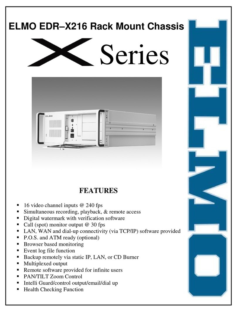
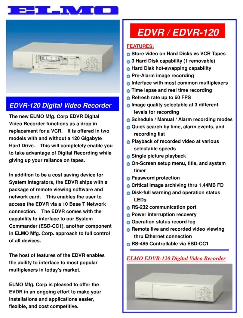
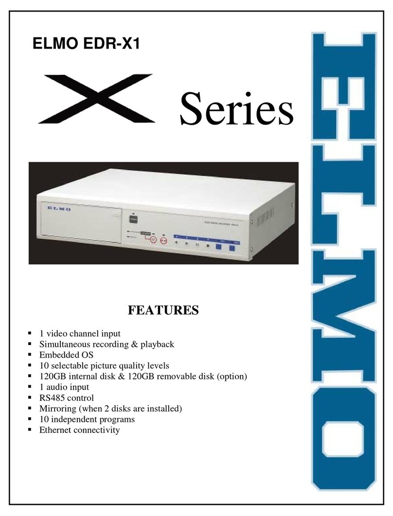
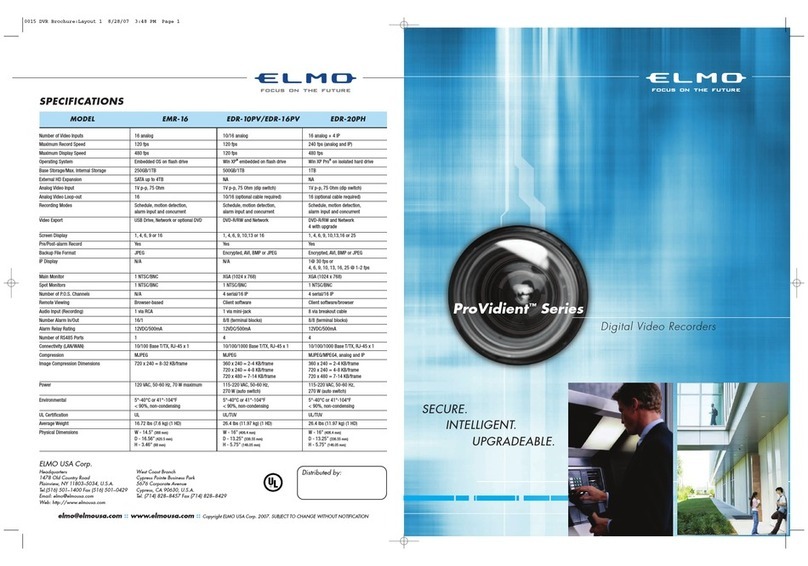
Elmo ProVidient EMR-16 User manual

16-ch Digital Hard Disk Recorder
EMR-16
Instruction Manual


Table of Contents
Introduction .................................................................................................................................1
Before Use ..................................................................................................................................5
Installation ..............................................................................................................................5
Use Environment...............................................................................................................5
Handling ............................................................................................................................5
Other Cautions .......................................................................................................................6
Recording Medium (Hard Disk) and Radiating Fan...........................................................6
Motion Detect (Movement Detection) Function .................................................................6
System Structuring ............................................................................................................6
Ethernet Terminal ..............................................................................................................6
When Malfunction Occurs .................................................................................................6
Handling of Recorded Data ...............................................................................................6
Features .................................................................................................................................7
Accessories............................................................................................................................8
Names and Functions .................................................................................................................9
Front Face..............................................................................................................................9
Back Face ............................................................................................................................11
Connection................................................................................................................................12
Standard Connection Example.............................................................................................12
Example of Connection with VP Power Unit (VC90P, etc) ...................................................13
Example of Connection with Alarm Devices.........................................................................14
Example of Connection with External Control Equipment....................................................15
Example of Connection with External Storage Media ..........................................................16
Example of Connection of PTZ Camera ..............................................................................16
Example of Connection with Expansion Hard Disk Unit.......................................................17
How To Use...............................................................................................................................18
Starting Up ...........................................................................................................................18
Turning Off ...........................................................................................................................18
Viewing Live Feeds ..............................................................................................................19
Screen Display While Showing Live Feeds.....................................................................19
Switching Cameras .........................................................................................................20
Display in Split Screen.....................................................................................................20
Automatic Sequence Display ..........................................................................................22
PTZ Camera Control .......................................................................................................22
2X Digital Zoom Display ..................................................................................................24
Viewing Live Feeds from Monitor 2 .................................................................................24
Recording.............................................................................................................................25
Screen Display During Recording ...................................................................................25
Manual Recording ...........................................................................................................26
Using Automatic Recording Mode ...................................................................................26
Playback...............................................................................................................................27
Screen Display During Playback .....................................................................................27
Playback/Stop Playback ..................................................................................................28
Changing Playback Speed ..............................................................................................29
Playback Frame by Frame ..............................................................................................29
Playback at Fast Speed...................................................................................................30
Display in Split Screen.....................................................................................................30
How to Use LAYOUT Function.............................................................................................31
Finishing LAYOUT Function ............................................................................................33
Search and Playback Recorded Video ................................................................................34
Copy Function ......................................................................................................................38
i
How to Copy....................................................................................................................38

Stop Copying...................................................................................................................41
Image File Format Copied to USB Media .......................................................................41
Image File Format Copied to DVD ..................................................................................41
WEB Server Function ...............................................................................................................42
Functions .............................................................................................................................42
Physical Connection Configuration......................................................................................42
Operation Environment ........................................................................................................42
Login/Logout ........................................................................................................................43
LIVE FEED...........................................................................................................................45
PLAYBACK ..........................................................................................................................46
MENU ..................................................................................................................................49
E-Mail Function ....................................................................................................................51
How To Set Up..........................................................................................................................52
How to Start and Finish Menu Mode....................................................................................52
Operation of Menu Screen...................................................................................................54
List of Menu Functions.........................................................................................................55
Main menu screen ...............................................................................................................59
Recording Setup ..................................................................................................................60
Recording Conditions Setup ...........................................................................................61
Recording Schedule Setup .............................................................................................63
Concurrent Recording Camera Setup.............................................................................65
Holiday Setup..................................................................................................................66
Motion Setup ...................................................................................................................67
Screen Display Setup ..........................................................................................................69
OSD Display Setup .........................................................................................................70
Monitor Output Setup ......................................................................................................72
Automatic Sequence Setup.............................................................................................73
Camera Name Setup ......................................................................................................74
Network Setup .....................................................................................................................75
E-mail Setup ........................................................................................................................76
Sending Condition Setup ................................................................................................78
System Setup.......................................................................................................................79
Control Camera Setup Screen ........................................................................................80
User Setup ......................................................................................................................81
Log Display ..........................................................................................................................83
Recording Log.................................................................................................................83
Error Log .........................................................................................................................84
Startup Log......................................................................................................................85
User Log..........................................................................................................................86
Equipment Maintenance ......................................................................................................88
Writing Method ................................................................................................................89
How to Format Hard Disks ..............................................................................................89
Operation Under Error Status ...................................................................................................91
Hard Disk Error ....................................................................................................................91
Video Loss .............................................................................Error! Bookmark not defined.
Output under Error Status....................................................................................................92
Troubleshooting ........................................................................................................................93
Warranty and Services .............................................................................................................94
Warranty..........................................................................................................................94
When requesting repair during warranty period ..............................................................94
Repair after expiration of warranty period .......................................................................94
Inquiry .............................................................................................................................94
ii
Repair Parts ....................................................................................................................94

iii
Specifications ............................................................................................................................95
Appendix ...................................................................................................................................99
Recording Time Table ..........................................................................................................99
JPEG Display Software: “Resize Viewer” ..........................................................................113
Specifications ................................................................................................................113
Operation Requirements ...............................................................................................113
Screen Display and Operation ......................................................................................114
File Display Order..........................................................................................................115
External Dimensions ..........................................................................................................116


Introduction
Thank you very much for your purchasing ELMO Digital Video Recorder. Before use,
please read this Instruction Manual carefully so that you may be able to use your
newly acquired digital video recorder properly.
After reading, be sure to keep it handy for reference.
The lightning flash with arrowhead symbol, within an equilateral triangle, is intended to alert
the user to the presence of uninsulated "dangerous voltage" within the product's enclosure
that may be of sufficient magnitude to constitute a risk of electric shock to persons.
The exclamation point within an equilateral triangle is intended to alert the user to the
presence of important operating and maintenance (servicing) instructions in the literature
accompanying the appliance.
CAUTION
Do not use any power supply other than specified.
WARNING
TO REDUCE THE RISK OF FIRE OR ELECTRIC SHOCK, DO NOT EXPOSE THIS
APPLIANCE TO RAIN OR MOISTURE.
This class A digital apparatus meets all requirements of the Canadian Interference-Causing
Equipment Regulations.
Cet appareil numérique de la classe A respecte toutes les exigences du Règlement sur le
matériel brouilleur du Canada.
INFORMATION
This equipment has been tested and found to comply with the limits for Class A digital
device, pursuant to Part 15 of the FCC Rules. These limits are designed to provide
reasonable protection against harmful interference when the equipment is operated in a
commercial environment.
This equipment generates, uses, and can radiate radio frequency energy and, if not
installed and used in accordance with the instruction manual, may cause harmful
interference to radio communications.
Operation of this equipment in a residential area is likely to cause harmful interference in
which case the user will be required to correct the interference at his own expense.
USER-INSTALLER CAUTION: Your authority to operate this FCC verified equipment could
be voided if you make changes or modifications not expressly approved by the party
responsible for compliance to Part of the FCC Rules.
- 1 -

IMPORTANT SAFETY INSTRUCTIONS
1. Read these instructions.
2. Keep these instructions.
3. Heed all warnings.
4. Follow all instructions.
5. Do not use this apparatus near water.
6. Clean only with dry cloth.
7. Do not block any ventilation openings. Install in accordance with the manufacturer's
instructions.
8. Do not install near any heat sources such as radiators, heat registers, stoves or other
apparatus (including amplifiers) that produce heat.
9. Do not defeat the safety purpose of the polarized or grounding-type plug.
A polarized plug has two blades with one wider than the other. A grounding type
plug has two blades and a third grounding prong. The wide blade or the third prong are
provided for your safety. If the provided plug does not fit into your outlet, consult an
electrician for replacement of the obsolete outlet.
10. Protect the power cord from being walked on or pinched particularly at plugs, convenience
receptacles, and the point where they exit from the apparatus.
11. Only use attachments/accessories specified by the manufacturer.
12. Use only with the cart, stand, tripod, bracket, or table specified by the
manufacturer, or sold with the apparatus. When a cart is used, use caution
when moving the cart/apparatus combination to avoid injury from tip-over.
13. Unplug this apparatus during lightning storms or when unused for long
periods of time.
14. Refer all servicing to qualified service personnel. Servicing is required when the apparatus
has been damaged in any way, such as power-supply cord or plug is damaged, liquid has
been spilled or objects have fallen into the apparatus, the apparatus has been exposed to
rain or moisture, does not operate normally, or has been dropped.
15. The apparatus is not waterproofs, to prevent fire or shock hazard, do not expose this
appliance to rain or moisture and do not put any water source near this apparatus, such as
vase, flower pot, cosmetics container and medicine bottle etc.
16. Grounding or Polarization - This product may be equipped with either a polarized 2-wire AC
line plug (a plug having one blade wider than the other) or a 3-wire grounding type plug, a
plug having a third (grounding) pin. The 2-wire polarized plug will fit into the power outlet
only one way, This is a safety feature. If you are unable to insert the plug fully into the outlet,
try reversing the plug. If the plug still fails to fit, contact your electrician to replace your
obsolete outlet. Do not defeat the safety purpose of the polarized plug. The 3-wire
grounding type plug will fit into a grounding type power outlet. This is a safety feature. If you
are unable to insert the plug into the outlet, contact your electrician to replace your obsolete
outlet. Do not defeat the safety purpose of the grounding type plug.
17. Lightning - For added protection for this product during a lightning storm, or when it is left
unattended and unused for long periods of time, unplug it from the wall outlet and
disconnect the antenna or cable system. This will prevent damage to the product due to
lightning and power-line surges.
- 2 -

PRECAUTIONS
- Refer all work related to the installation of these products to qualified service
personnel or system installers.
- Do not operate the appliances beyond their specified temperature, humidity, or power
source ratings.
Use the appliance at temperatures within +5 °C - +40 °C (41 °F - 104 °F) and humidity below
80 %.
The input power source for this appliance is 120 V AC 60 Hz.
Performance and lifetime of hard disk drives are easily affected by heat (used at high
temperature) characteristically. It is recommended to use this appliance at temperatures
within +20 °C - +30 °C (68 °F - 86 °F).
- Handle the appliance with care.
Do not strike or shake, as this may damage the appliance.
- Do not strike or give a strong shock to the unit.
It may cause damage or allow water to enter the unit.
- Cooling Fan
Turn off the power when cleaning the unit. Otherwise it may cause injuries.
- Cleaning
Turn off the power when cleaning the unit. Otherwise it may cause injuries.
Do not use strong or abrasive detergents when cleaning the appliance body.
Use a dry cloth to clean the appliance when it is dirty.
When the dirt is hard to remove, use a mild detergent and wipe gently.
- Indication label
Refer to the indication labels placed on the back of the unit as to the indications of equipment
classification and power source, etc.
- Built-in hard disk drives
Hard disk drives are vulnerable to vibration. Handle them with care.
It is possible to damage them if they are moved while their motors are still running. Do not
move them just after turning their power on or off (for around 30 seconds).
When hard disk drive trouble occurs, replace it immediately. Consult your dealer for servicing.
When replacing the hard disk drivers, take notice of the following.
- Place the unit horizontally an a level surface. Do not place the unit in an upright position.
When stacking multiple units, clear a space of more than 5 cm from both sides, the top, the
bottom and the rear of the units.
- Avoid placing receptacles that contain liquids such as water near the unit.
- If liquid spills onto the unit, it may cause fire or an electric shock.
- Do not expose the unit to water or moisture, or try to operate it in wet areas.
- Wait until the dew evaporates in any of the following cases;
- The recorder is placed in an extremely humid place.
- The recorder is placed in a room where a heater has just been turned on.
- The recorder is moved from an air-conditioned room to a humid and high-temperature
room.
- We recommend that you make a note of your settings and save them. This will help when you
are required to change the system configuration, or when unexpected trouble or failure
occurs.
- 3 -
- Distributing, copying, disassembling, reverse compiling, reverse engineering and also
exporting in violation of export laws of the software provided with this product, is expressly
prohibited.

WARNING
Handling the cord on this product or cords associated with accessories sold with
this product, will expose you to lead, a chemical known to the State of California
to cause birth defects or other reproductive harm.
Wash hands after handling.
- 4 -

B
I
efore Use
Below are the reminders you definitely need to know before using the equipment.
nstallation
Use Environment
yInstall the equipment in the environment at temperatures within 5 to 40° and humidity between 30
and 80% (where no due condensation)
yWhen changing the place of installation, be sure to turn off the main power and pull off the power
plug from the outlet.
yDo not install at places exposed to dust, oily,smoke, steam, or direct sunlight. The equipment has a
air cooling fan system, and therefore, be sure to allow a space over 10 cm from the wall. Dust can
accumulate in the ventilating openings even in not dusty places. As use in such a condition can cause
abnormal internal temperature rising, clean the ventilating openings after turning the main power off
and disconnecting the power plug from the outlet. It is advisable to clean the ventilating openings
about once a year.
yDo not install the equipment in strong electromagnetic fields or radio waves.
yInstalling the equipment in close proximity to wireless devices such as radios or televisions can
result in poor reception.
yPlace the equipment at a level and stable place. Do not install the equipment sideways up.
yHard disks are installed inside the equipment. Shocks or vibrations can cause damages or
malfunctioning of the hard disks. Give due consideration to the installation environment.
Handling
yHard disks are installed inside the equipment. Handle with due caution so as not to give shocks or
vibrations regardless of operating or non-operating to avoid malfunctioning.
yDo not unplug the power cord during recording, playback or other operations.
- 5 -

Other Cautions
Recording Medium (Hard Disk) and Radiating Fan
yThe hard disk and radiating fan installed inside the equipment are expendables.
yWhen replacing, consult the reseller of your purchase. (Service is chargeable even during the
warranty)
yA reference life of the hard disk is about 3 years for replacement. (Be advised that this duration is
simply a reference, and by no means guarantees its performance)
Motion Detect (Movement Detection) Function
yIn order to use the motion detect function built into the equipment, conduct the required setup
according to the target to be detected.
yWhen constructing a system for giving an alarm sound in connection with the motion detect function
of the equipment, beware of malfunctioning. In order to avoid malfunctioning or non-functioning,
consider the use of appropriate sensors in combination.
System Structuring
yWhen controlling the equipment through the Ethernet terminal in a certain monitoring system setup,
malfunction of this equipment or external equipment due to the setup therein or the connection or
combination status of devices can affect the entire monitoring system.
yWhen structuring a monitoring system using this equipment, be advised to thoroughly confirm in
advance the operation after connecting or combining the equipment with other equipment.
Ethernet Terminal
yWhen considering network connection, be advised to consult the network administrators or
engineers about setup or equipment requirements in advance.
yThe network function of this equipment does not guarantee the connection with all other network
devices.
When Malfunction Occurs
yIn the event of malfunction, turn the main power off, disconnect the power cord from the outlet, and
contact your reseller. Leave the repair work to the specialized repair staff.
Handling of Recorded Data
yBefore conducting important recording, perform test recording to make sure of normal recording
operation. In the case of setup for long recording mode by lowering the resolution, confirm that the
video image quality necessary for recorded footage is secured.
yBe advised that no compensation is available for incidental damage caused by malfunction or
defective condition of this equipment or other equipment during recording (such as no recording, no
normal playback, loss or the recorded video or sound data, etc)
yThis equipment is capable of digital recording video images. Care is needed when recording
copyrighted footages.
yIn case monitor cameras are set up for the purpose of recording videos with this equipment, the
direction or location of cameras that are recording should take into consideration the protection of
privacy or portrait rights.
- 6 -
yVideo data recorded using this equipment can be regarded as the “personal information” stipulated in
the “Private Information Protection Law.” Due caution is needed for handling such video data.

Features
■High Quality Digital Video and Sound Recording
Compared to the conventional VTR using tape recording, digital recording onto a hard disk enables
recording of higher quality video and sound data. Unlike tape recording, rewinding or cuing takes very
little time..
The recording pixel size is 720×240 per video image. Highly recognized Motion-JPEG is adopted for
the data compression method during video recording. A variety of settings are available depending on
the purposes and total recording time by means of 4-level image quality setup and recording interval
setup ranging from the shortest of 1/60 second to the longest of 1 seconds.
Sound can be recorded simultaneously for any video recording setups.
■Maximum of 4 Units of Large Capacity Hard Disk Drives Can Be Mounted
Up to 4 large capacity hard disk drives can be mounted for recording video and sound.
Extended recording is possible by recording onto one hard disk at a time, or highly reliable mirror
recording is viable by recording onto 2 hard disks at the same time.
■Handling Input from 16 Cameras
16 input terminals for video signal are provided. The equipment is capable of receiving input from
standard video cameras and recording. The video quality and recording intervals can be separately set
up for each of the input cameras.
The video images from the input cameras can be displayed on the monitor according to the desired
purposes such as split-screen display or automatic sequence.
The monitor output comes in 2 lines (Monitor 1 and Monitor 2). The monitor display can be operated
separately for each output, capable of a wide variety of monitoring operations.
■Simultaneous Operation of Recording, Playback and Live Display
Playback of recorded video is possible while recording continues. (Duplex operation)
Playback image and live image can be displayed singly on the monitor or in screen splits. In the screen
split display mode, LAYOUT setup is also available wherein recording continues while playback image
from the hard disk as well as live camera images are simultaneously displayed.
There is no need to stop recording , so important scenes can be continuously recorded while checking
the recorded data.
■2 Types of Recording Modes
In addition to manual recording mode where recording is started by pushing the recording button,
automatic recording mode is programmed in which timer setup, alarm input or motion (movements on
the monitor) detection automatically starts recording operation according to the preprogrammed
schedules for each monitor camera.
In the automatic recording mode, timer setup, alarm input, and motion detection can be set up in
combination. This enables a flexible operation according to a variety of monitor requirements.
■Motion Detect (Movement Detection) Function
Automatic recording can be programmed for a situation wherein movement is detected within a certain
designated area of the recording range of an input camera.
■Convenient Functions of Search and Playback
By specifying recording date and time or events of recording start (manual, alarm input, motion
detection, etc), the desired recording video can be quickely searched.
- 7 -
Playback can be done at normal and high speed, as well as in reverse.

■Capable of Remote Monitoring Via Network
Ethernet terminal is provided as standard equipment enabling connection with networks.
By accessing the Web server installed in the equipment via multi-purpose browser from other hosts on
the same network, it is able to operate various functions such as distribution of live feeds from the
cameras, search or playback of recorded video, remote control or setup of the equipment, etc.
When connecting our-recommended PTZ cameras, these are also remotely controlled (RS-485) from the
browser screen.
Accessories
Below are the accessories of this equipment:
Power supply AC cable
Instruction manual
- 8 -
Cautionary statement

Names and Functions
Below are the names and functions of each control on this equipment:
Front Face
No. Name Description
①POWER Key When pushing the POWER switch while recording, playback or live
feed display, the screen display of Monitor 1, buzzer, and each
indicator will be turned OFF.
When pushing the POWER switch during recording, the recording
operation is continued though the screen display is turned off. The
screen is displayed when pushing the POWER switch again.
②RECORDING
Indicator
Indicates the recording status
Indicator ON: Recording in progress
Indicator OFF: Other than recording
ALARM Indicator
(Red)
Indicates whether alarm given or not
Indicator ON: Malfunction of equipment
Indicator OFF: Operation normal
HDD Indicator
Indicates the blank space of the hard disk
Green: Disk space is sufficient.
Orange: Disk usage is approaching maximum.
Red: Disk space is insufficient.
* Indicates only when <OVERWRITE> of “Recording Setup” is set in
“NO.”
③Camera Selection Key
Key ①~ ⑯
Selects the channel for full screen display of live feeds or playback
video.
The selection position can be set in the LAYOUT setting, and the
position synchronizes with the 16-split screen. (When there is L2 at the
default position whose default is L1, pushing 1 displays the L2 single
screen.)
Functions as cursor keys while Operation / Setup Display is showing
③: Up、⑥: Left、⑧: Right、⑪: Down、⑦: Select
①②④⑤⑨⑩⑫~⑯: Not able to use
- 9 -
⑦
①③④⑤
⑥
②
⑧

No. Name Description
④UP Key Increase the setup value
DOWN Key Decrease the setup value
SEARCH Key Used for search of recorded video data.
Pushing this key shows Search screen
When operation is possible, lamp on the key lights up.
Recording Key( )
/
Recording Stop Key
()
Starts or stops manual recording.
Pushing Recording Key starts manual recording, and pushing it again
stops the manual recording.
Lamp on the key lights up while manual recording in progress.
SEQ DISP Key Automatically switches video images according to the setup.
See “Automatic Sequence Setup” under “Screen Display Setup”
(→P.73) for how to set up
SCRN DIV Key Displays the Screen Division Setup screen. (→P.20)
MENU Key Displays the Operation / Setup Menu on the screen.
The key lamp lights up when operation is possible.
CAM Key When pushing this key in the single screen mode, PTZ camera control
menu is displayed.
MON 2 Key To be pushed when operating Monitor 2 output.
Pushing again puts back to operation of Monitor 1 output.
The key lamp lights up during operation of Monitor 2.
⑤Jog Dial
Shuttle Dial
Conducts jog or shuttle operation during playback or playback pause.
See “Changing Playback Speed” (→P.29)and “Playback Frame by
Frame” (→P.29).
⑥SKIP Key( ) Skips to the beginning and start playback in playback video screen.
Setup of playback video screen is in LAYOUT.(→P.31)
Playback/Pause Key
()
Plays back recorded video forward in playback video screen.
Setup of playback video screen is in LAYOUT.(→P.31)
Pauses the video during playback or backward playback.
Each time you push this key, the operation changes from play to pause
or from pause to play.
Stop Key( ) Stops the playback in playback video screen.
Setup of playback video screen is in LAYOUT.(→P.31)
Backward
Playback/Pause Key
()
Plays back recorded video backward in playback video screen.
Setup of playback video screen is in LAYOUT.(→P.31)
Pauses the video during playback or backward playback.
Each time you push this key, the operation changes from backward
play to pause or from pause to backward play.
Skip Key Skips to the last recorded position and plays backward in playback
video screen.
Setup of playback video screen is in LAYOUT.(→P.31)
⑦USB Port
(ARCHIVE)
Connects USB media. The recorded video data or setup status can be
stored onto the connected USB media.
USB Port
(MOUSE)
Connects USB Mouse. This equipment can be operated using the
connected USB mouse.
⑧DVD Drive DVD drive can be stored within. (Optional)
- 10 -
Jo
g
Dial Shuttle Dial

Back Face
LOOP THROUGH
No. Names Description
①POWER Switch Turns the power of this equipment on and off.
Pushing toward the right turns the power ON and toward the left
turns OFF.
②VIDEO IN Video input connectors for Channels ①~ ⑯.
Connect the video output terminals from cameras, or other devices
③AC Inlet Power in 120VAC 60Hz is supplied here to.
Connect the power cord to this inlet.
Disconnecting the cord from this inlet stops all functions of the
equipment.
④LOOP THROUGH Loop connectors for the video input of Channels ①~ ⑯. To be
used for distribution of video signals to other equipment.
⑤MONITOR OUT 1
MONITOR OUT 2
Output for video signal to be connected with monitors.
MONITOR 1: Capable of displaying live feeds, playback video
images, and setup display screen.
MONITOR 2: Only for displaying live feeds.
⑥AUDIO IN
AUDIO OUT
Input and output connectors for audio signals
⑦RS-485 Terminal
Block
6P Terminal Block for RS-485
⑧RS-485 Termination
Switch
To be set in ON in case no other equipment is connected after this
equipment when connecting RS-485
⑨Ethernet Terminal RJ-45 connector for Ethernet, capable of connecting with various
networks
⑩DISK ARRAY
CONTROL
Terminal for HDD expansion unit (EMR-ESU) control
(quadplex-pole quadplex-core), for connecting with the control
cable attached to EMR-ESU
⑪DISK ARRAY 1/2 e-SATA terminal for HDD expansion unit (EMR-ESU) connection,
connecting with the e-SATA cable attached to EMR-ESU
⑫ALARM Terminal
Block
Terminal Block for input and output of alarm signals
⑬GND Connects the grounding wire.
- 11 -
③④⑤⑥⑦⑧⑨⑩⑬⑫
①②⑪

Connection
Below are the instructions on how to connect the equipment with other equipment:
Caution
yWhen connecting this equipment with other equipment, be sure to turn off the power of all
equipment to be connected.
Standard Connection Example
LOOP THROUG H
CCD Camera
BNC-BNC
Coaxial Cable
BNC-BNC
Coaxial Cable
To Video Input
Terminal
To Camera Input Terminal
To Video Input
Terminal
1
16
1
16
BNC-BNC
Coaxial Cable
To Video Input
Terminal
Microphone
Control Equipment
Color Monitor
TV
Color Monitor
TV
Color Monitor
TV
To Video Input
Terminal
To Sound Input
Terminal
- 12 -

Example of Connection with VP Power Unit (VC90P, etc)
- 13 -
LOOP THROUGH
VP Power Unit
BNC-BNC
Coaxial Cable
BNC-BNC
Coaxial Cable
To Video Input
Terminal
To Video Input
Terminal
Color Monitor
TV
To Sound Input
Terminal
To Sound Output
Terminal
VP Multiple Camera
BNC-BNC
Coaxial Cable
1
16 To Camera Input Terminal
To Video Input Connector

Example of Connection with Alarm Devices
LOOP THROUGH
Control Equipment
Lights, etc
■Connection with Sensor
A sensor can be connected to the terminal block on the back as input from alarm signal. Use no-voltage,
normally open output type
Terminal Specification
Input / Output
Terminal Input / Output Terminal Circuit Signal Specification
・Alarm input VCC (+3.3V)
10kΩ
Alarm Input
GND
LVC245
TTL negative logic, or
no-voltage, normally
open output
Pulse width; over 100ms
・Alarm output
Maximum of DC24V、
Under 20mA
Alarm Output
GND
GND
- 14 -
Other manuals for ProVidient EMR-16
1
Table of contents
Other Elmo DVR manuals

Elmo
Elmo EDVR-120 User manual

Elmo
Elmo ProVidient EMR-16 User manual

Elmo
Elmo EDR-X04 User manual

Elmo
Elmo EDR-X04 User manual

Elmo
Elmo DVR V5.01 User manual

Elmo
Elmo EDR-X109 Compact User manual

Elmo
Elmo EDR-X1 User manual

Elmo
Elmo EDR-X216 User manual

Elmo
Elmo EDR-X1 Troubleshooting guide

Elmo
Elmo EDR-X109 Compact User manual