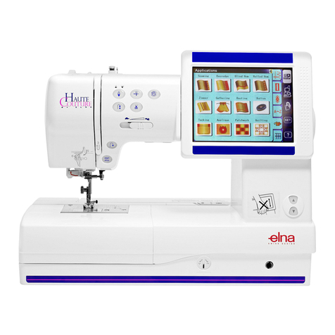
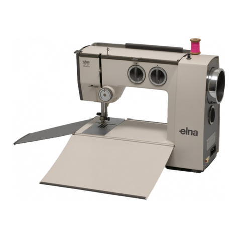
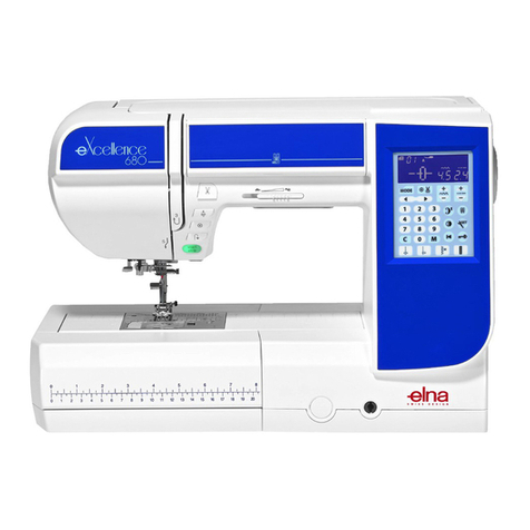
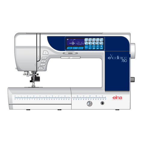
ELNA 7100 User manual

Servicing Manual

Replacing the External Parts
Face plate .....................................................................................................1
Top Cover......................................................................................................1
Belt Cover .....................................................................................................1
Motor Cover ..................................................................................................1
Base ..............................................................................................................1
Mechanical Adjustment
Needle Bar Height.........................................................................................2
Presser Bar Height........................................................................................2
Feed Dog Height ...........................................................................................3
Feed Dog Alignment......................................................................................3
Feed Cam Timing..........................................................................................4
Feed Lifting Cam Timing ...............................................................................5
Needle to Hook Timing..................................................................................6
Clearance between Needle and Hook Point .................................................6
Hook Stopper Position ..................................................................................7
Bobbin Winder Stopper .................................................................................8
Check Spring Stroke .....................................................................................9
Pre-tension Dial.............................................................................................9
Knee Lifter Lever.........................................................................................10
Needle Stop Position...................................................................................11
Needle Threader .........................................................................................12
Replacing the Electronic Components
Location of the Electronic Components ......................................................13
Location of the Connectors .........................................................................14
Internal Wiring .............................................................................................15
Circuit Board-A............................................................................................16
Circuit Board-F and Slide Volume ...............................................................16
Driving Motor......................................................................................... 17-18
Power Transformer......................................................................................19
Machine Socket...........................................................................................19
Light Bulb ....................................................................................................20
Adjustment of the Thread Cutter Mechanism
Static Cutter Blade ......................................................................................21
Thread Cutter Blade....................................................................................22
Thread Guide Plate .....................................................................................23
Needle to Cutter Cam Timing......................................................................24
Thread Drawing Lever.................................................................................25
Auto Tension Release .................................................................................26
Thread Cutter Troubleshooting....................................................................27
Parts List ..................................................................................................28
Table of Contents
1
Replacing the External Parts
1. Face Plate
2.Top Cover
3. Belt Cover
4. Motor Cover
5. Base
Remove the setscrew (4 x 10) q and washer w.
Remove the face plate e.
Remove the 2 setscrews (4 x 25) r.
Lift the top cover t and pull out the motor
connector y. Remove the top cover.
Remove the 3 setscrews (4 x 12) u and remove
the belt cover i.
NOTE:
When attaching the belt cover, engage the hooks
with the motor cover.
Remove the 3 setscrews (4 x 12) o and remove
the motor cover !0.
Remove the 4 hinge screws !1, washers !2,
rubber feet !3 and base washers !4. Remove
the base !5.
q
w
e
r
r
t
y
u
u
i!0
o
o
!1
!5
!1
!1
!1
!2
!3
Follow the above procedures in reverse.
To attach:
To remove:
!4

2
Mechanical Adjustment
1. Needle Bar Height
2. Presser Bar Height
zRemove the face plate.
xTurn the handwheel to bring the needle bar q to the
lowest position.
vLoosen the setscrew w.Move the needle bar q up
or down and match the upper hairline e with the
bottom edge of the needle bar bushing r.
NOTE:
Be sure not to rotate the needle bar when adjusting the
needle bar height.The needle clamp screw should be
parallel to the upper shaft.
bTighten the setscrew and attach the face plate.
q
e
r
w
The distance between the bottom of the presser foot in
up position and the needle plate should be 5.7–6.3 mm.
zRemove the face plate and needle.
xLower the feed dog below the needle plate. Place a
block 6 mm thick under the presser foot and lower the
presser foot lifter.
cLoosen the setscrew q. Raise the presser foot lifter
and tighten the setscrew qfirmly.
Attach the needle and face plate.
NOTE:
Make sure that the presser foot should be parallel to the
feed dog slots win the needle plate.
6 mm
q
w
Presser foot should be parallel
to the feed dog slots.

3
3. Feed Dog Height
When the feed dog is fully raised the height should be
0.8–1.0 mm above the needle plate.
zSet the stitch length dial at 6 (Maximum).Turn the
handwheel to bring the feed dog to the highest
position.
xLoosen the setscrew q.
cTurn the eccentric pin wto adjust the feed dog height
to 0.9 mm.
• If the feed dog is too low, turn the pin to the right e.
• If the feed dog is too high, turn the pin to the left r.
vTighten the setscrew q.
0.8–1.0 mm
qe
r
w
4. Feed Dog Alignment
The lateral gaps between both sides of feed dogs and
needle plate slots should be even.
The crealance between the front end of the center feed
dog and center slot should be 4.2–4.8 mm when the
stitch length dial is set at 0.
zRemove the base and lay the machine on its back.
xSet the stitch length dial at 0.
cLoosen the setscrews q. Move the feed base wup
or down to adjust the clearance e between the front
end of the center feed dog and center slot to 4.5 mm.
Adjust the lateral position of the feed dogs by moving
the feed rock shaft rto the right or left if neccessary.
vTighten the setscrews q.Set the stitch length dial at 6
and turn the handwheel to check if the feed dogs do
not touch the needle plate.
bAttach the base.
q
e
r
w
Lateral gaps should be even.
4.2–4.8 mm

4
5. Feed Cam Timing
To Check:
zLower the needle bar by turning the handwheel until
the point of the needle is 17.5 mm above the upper
surface of the needle plate q.
xThe feed dogs should not move when moving the
reverse stitch lever up and down.
If the feed dogs move, adjust the feed cam timing as
follows.
To Adjust:
zRemove the base and lay the machine on its back.
xLower the needle bar until the needle point is 17.5 mm
above the needle plate q.
cLoosen the setscrews w.
While moving the reverse stitch lever, turn the feed
cam ein the direction either Aor Buntil the feed
dogs stop moving.
vTighten the setscrews wand attach the base.
q
e
wA
B
17.5 mm

5
6. Feed Lifting Cam Timing
To check:
zLower the needle bar until the point of needle is level
with the upper surface of the needle plate q0.4 mm
below the needle plate .
xThe top of the feed dogs wshould be 0–0.1 mm
above the needle plate.
To adjust:
zRemove the base and lay the machine on its back.
xLower the needle bar until the needle point is level
with the needle plate qor 0.4 mm below the needle
plate .
cLoosen the setscrew e.
vIf the feed dogs are higher, turn the feed lifting cam r
in the direction A.
If the feed dogs are lower, turn the feed lifting cam r
in the direction B.
bTighten the setscrew eand attach the base.
e
w
q
q
r
A
B
0.4 mm
0–0.1 mm

6
7. Needle to Hook Timing
8. Clearance between Needle
and Hook Point
zRemove the needle plate.
xLoosen the 3 setscrews q. Pull out the hook race
very slightly (less than 0.5 mm).
cRaise the needle bar from the lowest position until the
lower heirline wof the needle bar matches the edge
of the needle bar bushing e.
NOTE:
The needle bar rises 2 mm from the lowest position.
vRotate the hook to match the hook point rwith the
right side of the needle.
bTighten the setscrews qslightly and proceed with the
adjustment of the clearance between the needle and
hook point.
r
q
w
e
Lowest position
2 mm
2 mm
The clearance between the needle and hook point should
be 0–0.1 mm.
zTurn the handwheel to bring the hook point qbehind
the needle w.
xKnock on the hook race rim lightly to make a slight
clearance between the needle and hook point.
NOTE:
Do not knock on the hook body.
cTighten the setscrews firmly and check the needle to
hook timing and the thread path e(0.4–0.8 mm).
vAttach the needle plate.
q
w
q
0–0.1 mm
0–0.1 mm 0.4–0.8 mm
e

7
9. Hook Stopper Position
zRemove the needle plate and base.
xLoosen the setscrew qand move the hook stopper w
so that the center of the needle eis located between
the center of th hook stopper rand outer side of the
hook stopper spring t.
cTighten the setscrew qand attach the needle plate
and base.
q
w
e
t
r
w

8
10. Bobbin Winder Stopper
The amount of thread wound on the bobbin should be
16.5–19.5 mm in diameter.
zLoosen the setscrew q.Turn the bobbin winder
stopper wto adjust the thread amount.
• If the amount is too mauch, turn the stopper in the
direction A.
• If the amount is not enough, turn the stopper in the
direction B.
cTighten the setscrew qfirmly.
q
w
A
B
16.5–19.5 mm

9
11. Check Spring Stroke
The amount of the needle thread supplied by the check
spring should be 11–15 mm.
zThread the machine up to the thread guide qand
lower the presser foot.
Lower the needle bar to the lowest position.
xHold the thread end and mark the point won the
thread beside the thread guide.
NOTE:
There should be no slack in the thread.
cPull the thread gently to the left until it stops (the
check spring ewent full stroke).
vMeasure the length of thread drawn out.
bLoosen the setscrew rand move the tension dial
guide tto adjust the stroke.
• If the length is too long, turn the guide in the direction A.
• If the length is too short, turn the guide in the direction B.
nTighten the setscrew r.
q
w
e
t
r
q
r
A
B
11–15 mm
12. Pre-tension Dial
The standard position of the pre-tension dial is as follows:
The screw head qsinks 4 mm below the dial face.
q
w
4 mm

10
13. Knee Lifter Lever
The presser foot rises 7.5 mm when it is fully raised with
the knee lifter.
zRemove the base and lay the machine on its back.
xLoosen the nut qon the knee lifter lever wslightly
and turn the adjusting screw eto adjust the height.
• If it is lower than 7.5 mm, turn the adjusting screw e
clockwise.
• If it is higher than 7.5 mm, turn the adjusting screw e
counterclockwise.
cTighten the nut qfirmly and attach the base.
NOTE:
Lower the needle bar to the lowest position and check if
the needle cramp does not hit against the presser foot
when it is fully raised.
7.5 mm
qw
e

11
14. Needle Stop Position
zTurn the power switch qon while pressing the Up/
Down needle position button wand bobbin winding
button eat the same time.
xRemove the top cover.
cLower the needle bar by turning the handwheel until
the needle point is 18.7 mm above the upper surface
of the needle plate r.
vLoosen the setscrew t. Rotate the upper shaft
shielding plate ytoward you until the green LED u
turns on.
bTighten the setscrew tand turn the power switch off.
nAttach the top cover.
q
we
t
r
y
u
18.7 mm

12
15. NeedleThreader
To remove:
zRemove the face plate.
xPull the threader qout from the threader shaft w.
To attach:
vAlign the groove eof the theader with the pin ron
the threader shaft. Push the threader up until it snaps
in place.
To adjust:
zIf the threader hook qthrusts or hits against either
left or right edge of the needle eye w:
Loosen the setscrew e. Move the threader plate r
to adjust the lateral position of the threader hook q.
xIf the threader hook qthrusts or hits against either
top or bottom edge of the needle eye w, or misses
the needle eye w:
Loosen the setscrew t. Move the threader position
setting plate yup or down to adjust the vertical
position of the threader hook q.
qw
e
t
r
y
q
w
q
w
e
r

13
Replacing the Electronic Components
Lamp
Circuit board-F
Slide volume
Circuit board-A
Bobbin winder motor Bobbin winder switch
Upper shaft sensor
Driving motor
Machine socket
Power transformer
Circuit borad-MS
Arm lamp
Thread cutter switch
Capacitor
Push-pull solenoid
1. Location of the Electronic Components

14
Motor sensor
Circuit borad-F
Thread cutter switch*
Machine socket (primary)
Power transformer
(primary)
Driving motor
Machine socket (secondary)
Slide volume
Arm lamp
Power transformer
(secondary)
Bobbin winder
switch
Push-pull
solenoid*
Capacitor*
Upper shaft sensor
Lamp
2. Location of the Connectors

15
3. Internal Wiring
Motor cord
Motor sensor cord
Machine socket cord (primary)
Machine socket cord (secondary)
Push-pull solenoid cord*
Capacitor cord* Cord binder
Cord guide (1)
Thread cutter cord* Cord guide (2)
Motor cord
Motor censor cord
Cord guide (1)
Setscrews for cord guide (1)
To prevent the internal wirings from contacting the moving parts or being caught in the joint of the external
parts, the internal wirings should properly be routed and secured as illustrated.
Cord binder

16
4. Circuit Board-A
To remove:
zRemove the top cover.
xPull out connectors from the circuit board-A.
Remove the cords from the cord clips q.
cRemove the setscrews wand the board-A
case lid e.
vPull out the connectors under the case lid.
Remove setscrews rand circuit board-A.
To attach:
bInstall the circuit board-A and secure it with
the setscrews r.
nInsert the following connectors:
tMachine socket (primary)
yPower transformer (primary)
uDriving motor
nAttach the board-A case lid eand secure it
with the setscrews w.
,Insert the remaining connectors and secure
the cords with the cord clips qon the case lid.
.Attach the top cover.
NOTE:
Do not disconnect the connectors by pulling on cord.
To disconnect, grasp the connector, not the cord.
5. Circuit Board-F and Slide Volume
zRemove the top cover.
xLoosen the 4 setscrews qand remove the
ornamental panel w.
cPull out the circuit board-F connector from the
circuit board-A. Remove the 3 setscrews e
and circuit board-F r.
vPull out the slide volume connector from the
circuit board-A. Remove the CS rings tand
slide volume y.
bTo attach: follow the above procedure in
reverse.
NOTE:
Do not disconnect the connectors by pulling on cord.
To disconnect, grasp the connector, not the cord.
qw
e
r
r
t
y
u
qw
e
t
r
qq
w
y

17
6. Driving Motor
To remove:
zRemove the belt cover and motor cover.
xPull out the motor sensor connector q.
cPull out the motor connector w, while pushing the
connector lock e.
vRemove the nuts rand driving motor t.
NOTE:
Do not disconnect the connectors by pulling on cord.
To disconnect, grasp the connector, not the cord.
(to be continued on next page.)
q
r
t
e
w
w

18
6. Driving Motor (continued)
To attach:
zInstall the driving motor qto the motor bracket wand
attach the motor belt e.Tighten the nuts rfirmly.
xLoosen the setscrews tslightly and move the motor
up or down to adjust the motor belt tension.
The belt should deflect 4–5 mm when applying 300
grams of load to the middle of the belt.
Tighten the setscrews tfirmly.
cInsert the motor connector yand motor sensor
connector u.
vAttach the motor cover and belt cover.
q
w
e
t
r
y
Motor belt tension
4–5 mm
Table of contents
Other ELNA Sewing Machine manuals

ELNA
ELNA eXperience 660 User manual

ELNA
ELNA eXcellence 792PRO User manual

ELNA
ELNA CE10 User manual

ELNA
ELNA 3210 JEANS - User manual

ELNA
ELNA Lotus User manual

ELNA
ELNA 7300 - User manual

ELNA
ELNA Xquisit II User manual

ELNA
ELNA eXperience 620 User manual

ELNA
ELNA Sew Fun User manual

ELNA
ELNA 6005 heirloom edition User manual

ELNA
ELNA eXperience 550 User manual

ELNA
ELNA Elina 21 User manual

ELNA
ELNA Cover Pro 2000CPX Troubleshooting guide

ELNA
ELNA eXpressive 970 User manual

ELNA
ELNA 5200 User manual

ELNA
ELNA eXpressive 900 User manual

ELNA
ELNA 444 User manual

ELNA
ELNA Lock L4 User manual

ELNA
ELNA EN VISION CE 20 - LEAFLET User manual

ELNA
ELNA 654 - User manual