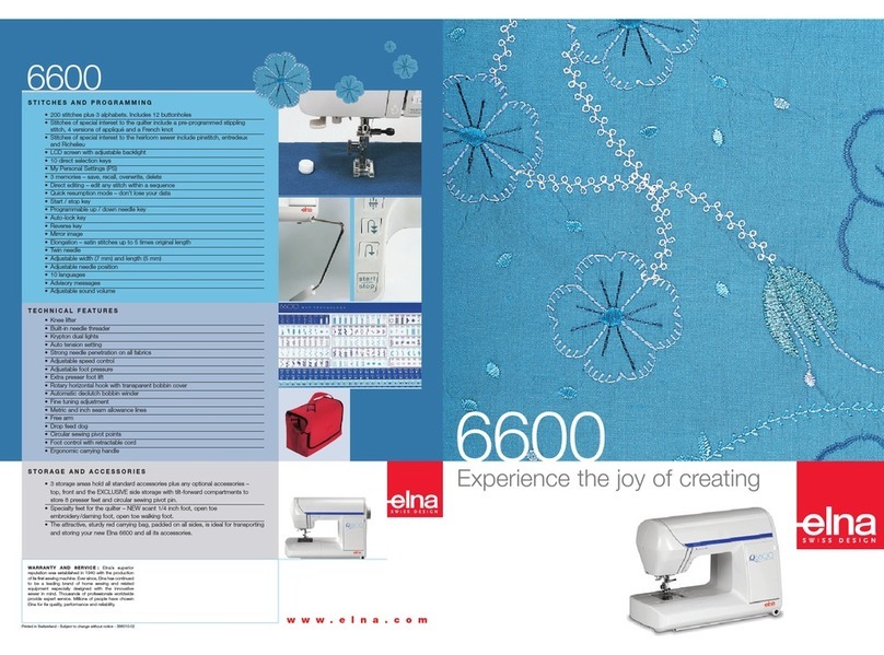
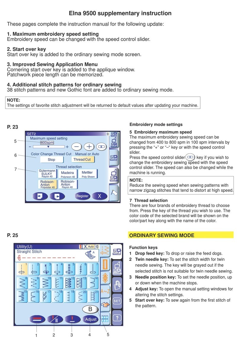
ELNA 9500 - LEAFLET User manual

SERVICING MANUAL
9500

Changing External Parts (1) ...................................................................................... 1
Changing External Parts (2) ...................................................................................... 2
Changing External Parts (3) ...................................................................................... 3
Changing External Parts (4) ...................................................................................... 4
Changing External Parts (5) ...................................................................................... 5
Changing External Parts (6) ...................................................................................... 6
Changing Thread Tension Uni.................................................................................... 7
Replacing the Thread Cutter unit ............................................................................... 8
Replacing Needle Threader Motor (1) ....................................................................... 9
Replacing Needle Threader Motor (2) ...................................................................... 10
Connector Connection Diagaram.............................................................................. 11
Replacing Printed Circuit Board A ............................................................................ 12
Replacing Printed Circuit Board F1, F2/Slide Volume .............................................. 13
Replacing Printed Circuit Board B ........................................................................... 14
Replacing Switching Power Supply........................................................................... 15
Replacing DC Motor and Motor Belt Tension Adjustment......................................... 16
Adjusting Needle Drop Position ................................................................................ 17
Adjusting Hook Timing .............................................................................................. 18
Adjusting Needle Bar Height..................................................................................... 19
Adjusting Clearance between Needle and Hook ...................................................... 20
Adjusting Backlash between Hook Drive Gear and Lower Shaft Gear ..................... 21
Adjusting Presser Foot Position and Height.............................................................. 22
Adjusting Feed Dog Height ....................................................................................... 23
Adjusting Height of Embroidery Foot P..................................................................... 24
Adjusting Upper Shaft Shield Plate Position ............................................................. 25
Adjusting Tension Release Mechanism ................................................................... 26
Adjusting Needle Thread Tension ............................................................................. 27
Replacing Threader Plate and Adjustment ............................................................... 28
Adjusting Needle Threader Switch............................................................................ 29
TTP Adjusting Mode ................................................................................................. 30
Adjusting Stretch Stitch Balance............................................................................... 31
Adjusting Presser Foot Lifter Sensor ........................................................................ 32
Adjusting Buttonhole Lever ....................................................................................... 33
Adjusting Presser Foot Sensor ................................................................................. 34
Adjusting Remaining Bobbin Thread Sensor ............................................................ 35
Adjusting Thread Cutter Solenoid ............................................................................. 36
Adjusting Upper Shaft Clutch Solenoid..................................................................... 37
Adjusting Thread Cutter Switch ................................................................................ 38
Adjusting Bobbin Winder Stopper ............................................................................. 39
INDEX

Adjusting Thread Drawing Lever ............................................................................... 40
Adjusting X andY Sensors ....................................................................................... 41
Adjusting the Sewing Start Position .......................................................................... 42
Setting Position of Thread Take Up lever .................................................................. 43
To Adjust Upper Shaft Declutch Device .................................................................... 44
Setting Position of Parts on Lower Shaft................................................................... 45
Setting Position of the Upper and Lower Shafts ....................................................... 46
INDEX

1
9500
Changing External Parts (1)
To remove:
1Remove Screws (A) (2 pcs) and remove the face
cover .
To attach:
2Follow the above procedure in reverse.
Replacing the face cover
Replacing the top cover
To remove:
1Open the face cover.
2Remove the caps (2 pcs), Screw (B) and Screw
(C).
Raise the carrying handle and remove Screw (D).
3 Raise the top cover and disconnect the bobbin
winder connector .Renove the top cover from rear
side.
• Presser dial comes off together.
To attach:
4 Raise the carrying handle, insert the top cover
from rear side.
5Connect the bobbin winder connector to the A
board.
6Tighten Screws (B), (C), (D).
7Attach the caps.
e
q
q
w
r
(A)
e
r
w
w
(B)
(C)
(D)

2
9500
Changing External Parts (2)
Replacing the belt cover
To remove:
1 LoosenScrew(A).
2Remove the Caps and remove Screws (B) and
(C).
3Remove the hook under the belt cover while push
ing below and remove the belt cover.
To attach:
4Match the belt cover position with the front cover.
5Attach the belt cover while pushing the hook below.
6 Tighten the Screws (A), (B) and (C).
7 Attach the caps .
w
(A)
(B)
(C)
q
q
w
q

3
9500
Changing External Parts (3)
Replacing the bed cover
To remove:
1 Remove the extension table.
2Remove Screws (A) (2 pcs) and remove the bed
cover.
To attach:
3Follow the above procedure in reverse.
(A)

4
9500
Changing External Parts (4)
Replacing the base
To remove:
1 Remove the extension table.
2Remove the belt cover.
3Disconnect the connector from the printed circuit
board S1 .
4Loosen Screws (A) and (B) and remove the base.
To attach:
5Insert the connector cords between the base and
arm. Make sure that the cords should not be
caught between the arm and base unit when
attaching it, then tighten Screws (4 pieces) temporarily.
6Attach the extension table.
7Match the extension table, base and free arm
position and tighten Screw (B).
8 Tighten the rest of Screws (A).
9 Insert the connector tothe printed circuit
board S1 from below the releasing arm .
10 Attach the belt cover.
q
w
qw
(A) (A)
(A) (B)
e
e

5
9500
(A)
(B)
(C)
(D)
Changing External Parts (5)
To remove:
1Open the face cover and remove the top cover, belt
cover and extension table.
2Loosen Screw (A) and remove the arm thread guide
(rear) .
3Loosen Screw(B).
4Loosen Screw (C) and remove (D).
5Disconnect the each connector and remove the front
cover.
Note: Unlock the hooks while removing the front
cover.
To attach:
6Follow the above procedure in reverse.
Front cover
q
q
w
w

6
9500
(A)
(B)
(C)
(D)
Changing External Parts (6)
1 Remove the face cover, top cover and belt cover.
2Loosen Screws (A), (B), (C) and remove Screw (D)
and remove the rear cover.
Note: Lower the presser foot.
To attach:
3Follow the above procedure in reverse.
Rear cover
To remove:

7
9500
(A)
(B)
ChangingThreadTension Unit
To remove:
1 Remove the front cover.
2.Lowerthepresserfootlifter.
3 Remove Screws (A), (B).
4 Pull the connector out from the “U”board and remove
the thread tension unit.
To attach:
3 Follow the above procedure in reverse.
Note: After changing the thread tension, check the
tension release mechanism. (See page 26)

8
9500
1Remove the needle plate and bed cover.
2 Loosen Screw (A) and remove the thread
cutter cover .
3 Remove Screws (B) (2 pcs) and remove the thread
cutter unit.
4 Insert the pin and into the thread cutter hole and
attach the thread cutter unit by Screw (B).
Note: After changing the thread cutter unit, check the
driving arm function with turning the
handwheel.
1 Lower the needle bar at its lowest position.
2 Push the driving arm (1) down and insert
the pin into the ditch of the cutter driving
cam .
3 Turn the handwheel to drive the cutter slide
plate.
4 Driving arm (1) disengage from the stopper
and return to the home position (upper
position).
(B)
(B)
(A)
Replacing theThread Cutter unit
q
q
q
w
qw
e
r
t
r
r
e
t
q

9
9500
To remove:
1Remove the face cover and the top cover.
2 Loosen the Screw (A).
3 Disconnect the bobbin winding motor and the needle
threader sensor from the printed circuit board “U”.
* Remove the cords from cord guide .
4Remove Screws (B) (2 pieces) and remove the motor.
* Remove the lamp supporter before replace the motor.
(A)
(B)
Replacing NeedleThreader Motor (1)
q
q
w
w

10
9500
Replacing NeedleThreader Motor (2)
To attach:
5 Insert the convex part of the needle bar supporter
into the forked part of the moval body .
6 Attach the motor by Screw (B).
7 Insert the each cord in the cord guide and connect
to the circuit board “U”.Attach the front cover.
8 Attach the face cover and top cover.
Needle threader motor unit
Lamp supporter
q
q
w
w
e
e

11
9500
Connector Connection Diagaram
Please see the following connector connection diagram for the printed circuit board
A and U.
Printed circuit board R (White)
Bobbin winder (Black)
Printed circuit board U
(Black)
Printed circuit board L2 (Gray)
Printed circuit board L2 (White)
Printed circuit board F1 (Red)
Printed circuit board F2 (Black)
Slide volume (Red)
Printed circuit board B (Black)
Printed circuit board U (Black)
LCD Motor (Top/Bottom)
Printed circuit board P (Black)
Printed circuit board Q (Black)
Feed motor (Red)
Printed circuit board S1 (Black)
Presser foot lifter sensor (Brown)
P foot sensor (Blue)
Printed circuit board A (Black)
Printed circuit board L3 (Gray)
Printed circuit board A (Black)
Needle threader motor (Black)
Printed circuit board A
LCD detection switch
(Top position)(Blue)
LCD detection switch
(Bottom position)(Brown)
Switching regulator (White)
DC Motor (White)
Remaining bobbin thread
solenoid (Black)
Thread cutter solenoid
(White)
Upper shaft disconnect
solenoid (Red)
Potention meter (Blue) Needle threader motor detection
switch (Bottom)(Brown)
Needle threader motor
detection switch (Top)(Blue)
Buttonhole sensor (White)
Thread cutter sensor (Black)
Printed circuit board U
Zigzag width motor (Black)
Ttread tension motor (Gray)

12
9500
(A)
(A)
Replacing Printed Circuit Board A
To remove:
1 Remove the front cover.
2 Disconnect the each connector from the printed
circuit board A.
3. Remove Screws (A) (8 pieces) and remove the
printed circuit board A with the Card guide .
To remove:
4 Follow the above procedure in reverse.
q
q

13
9500
(A)
(B)
Replacing Printed Circuit Board F1, F2/Slide Volume
Printed circuit board F1
To remove:
1Remove the front cover.
2Pull out the connector from the printed circuit
board A.
3Remove Screws (A) (2 pieces) and remove
the Printed circuit board F 1 .
To attach:
4Follow the above procedure in reverse.
Printed circuit board F2
To remove:
1Remove the front cover.
2Pull out the connector from the printed circuit
board A.
3Remove Screws (B) (3 pieces) and remove
the Printed circuit board F 2 .
To attach:
4Follow the above procedure in reverse.
Slide volume
To remove:
1Remove the front cover.
2 Pull out the Slide volume connector from the
printed circuit board A.
3 Remove the CS ring (2 pieces) and remove
the slide volume .
To attach:
4Follow the above procedure in reverse.
q
q
w
w
e
e
r
r

14
9500
(A)
Replacing Printed Circuit Board B
To remove:
1Remove the belt cover.
2Remove the base .
3 Remove Screws (A) (2 pieces) and remove
the Printed circuit board B case and
circuit board B .
3 Disconnectthe Herness from the B board.
To attach:
4Follow the above procedure in reverse.
e
q
q
w
w
w
e
r
r

15
9500
(A)
(B)
Replacing Switching Power Supply
To remove:
1Remove the top cover, belt cover, base, and rear
cover.
2Remove Screws (A) and (B), and remove the
switching power supply .
3Disconnect the herness from switching power
supply.
To attach:
4Follow the above procedure in reverse.
q
q
w
w

16
9500
(A)
(A)
Replacing DC Motor and Motor BeltTension Adjustment
Replacing DC Motor
To remove:
1Remove the belt cover.
2Remove the motor belt.
3Disconnect the Motor connector from the printed cir
cuit board A.
4Remove Screws (A) (2 pieces) and replace the
motor.
To attach:
5 Follow the above procedure in reverse.
Adjusting motor belt tension
1 Tighten Screws (A) (2 pieces) temporarily.
2 Adjust the Belt deflection to about 5.0 mm by
pressing the middle of the motor belt with your
finger with approximately 200 grams of pressure .
3 Tighten Screws (A) securely.
4 Attach the belt cover.
q
q
w
w

17
9500
A = B
(A)
Adjusting Needle Drop Position
When the straight stitch is selected on the touch panel, the needle should be positioned in
the center of the needle plate hole.
When the zigzag stitch is selected with the zigzag width set to the maximum (7.0 ), the
clearance between the side of the needle and the edge of hole of the needle plate at the left
and right needle position should be 0.2 mm or more.
1Remove the top cover and slect the pattern No. 1
(Straight stitch).
Lower the needle to its lowest position by turning the
handwheel toward you.
2Loosen the Screw (A).
Move the Zigzag rod left or right to set the needle
in the center of the Hole of the needle plate , then
tighten Screw (A).
3Select the pattern No.6 (Zigzag).
Set the zigzag width to maximum (7.0).
4Turn the handwheel toward you to check if the
clearance between the side of the needle and the
edge of the Hole of the needle plate , at the left
and right needle position, is 0.2 mm or more .
5 Attach the top cover.
q
q
w
we
e
e
r
rr
Other manuals for 9500 - LEAFLET
2
Table of contents
Other ELNA Sewing Machine manuals

ELNA
ELNA Supermatic User manual

ELNA
ELNA Cover Pro 2000CPX Troubleshooting guide

ELNA
ELNA Creative Series User manual

ELNA
ELNA 664 - User manual

ELNA
ELNA 7100 User manual

ELNA
ELNA Sew Fun User manual

ELNA
ELNA Sew Green User manual

ELNA
ELNA Elnita User manual

ELNA
ELNA expressive 940 User manual

ELNA
ELNA eXplore 320 User manual

ELNA
ELNA 3210 User manual

ELNA
ELNA Sew75 User manual

ELNA
ELNA 3210 User manual

ELNA
ELNA EN VISION CE 20 - LEAFLET User manual

ELNA
ELNA 8300 - LEAFLET User manual

ELNA
ELNA xquisit User manual

ELNA
ELNA eXcellence 792PRO User manual

ELNA
ELNA XPRESSIVE 2 User manual

ELNA
ELNA 5100 - User manual

ELNA
ELNA 7300 - User manual