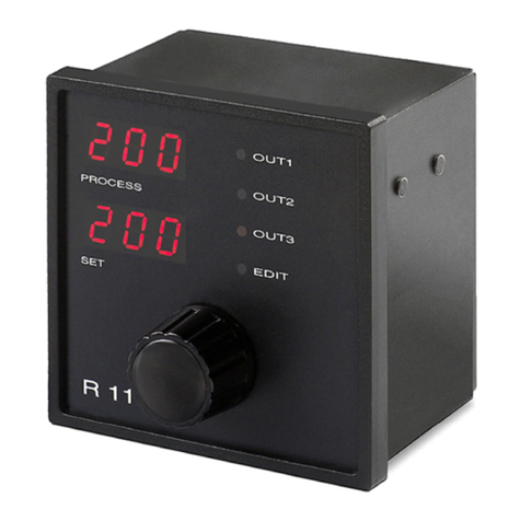
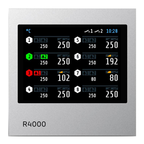
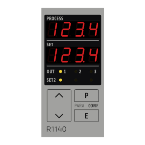
Elotech R2000-N4 Series Manual

R 2000 - N4 . .
Temperature Controller
4 - Zones „heat-only”
4 - Zones „heating-off-cooling“
Installation depth: 122 mm
DIN-Format: 96 x 96 mm
escription and operating manual
ELOTECH Ind strieelektronik GmbH
Verbind ngsstraße 27
D - 40723 HILDEN
FON +49 2103 / 255 97 0 FAX +49 2103 / 255 97 29
www.elotech.de Email: [email protected]
Man al: R2000-N4XX-X-000-X-X_EN Release: 2.02 © Elotech GmbH Page1/28

1 Contents
1 Contents..........................................................................................................2
2 General Information ........................................................................................3
3 Installation Instr ctions....................................................................................3
4 Type Code.......................................................................................................4
5 Connection Diagram.........................................................................................5
5.1 Power S pply and O tp ts..........................................................................5
5.2 Sensor Inp ts.............................................................................................7
6 Display and Keyboard........................................................................................8
6.1 Tendency Display........................................................................................9
6.2 Operating Levels.......................................................................................10
7 Parameter descriptions:...................................................................................12
7.1 Config ration Parameters, Valid for the Complete Device.............................12
7.2 Zone Config ration....................................................................................16
7.3 Control Parameters, Zone Dependent ........................................................20
7.4 Operating Level........................................................................................24
8 Error Messages................................................................................................25
9 Technical Data.................................................................................................26
10 Notes............................................................................................................27
Man al: R2000-N4XX-X-000-X-X_EN Release: 2.02 © Elotech GmbH Page2/28

2 General Information
Messages shown by the controller display
<§> Symbolizes the val e of the factory adj stment of the respective
parameters.
>3< This parameter is available in 3-point controllers only.
3 Installation Instructions
Make certain that the device is sed for the intended p rpose only.
R2400 controllers are designed for installation in control panels.
Protect the device against impermissible h midity and contamination.
Ambient temperat re may not exceed 50 °C (122 °F).
Electrical connections m st be made according to valid reg lations and by properly q alified
personnel.
If sing thermoco ple sensors, compensation lines have to be connected directly to the controller
terminals. Sensors may be connected only in compliance with the programmed range.
Sensor cables and signal lines (e.g. logic or linear voltage o tp ts) m st be laid separately from
control lines and mains voltage s pply cables (power cables).
It is not permitted to connect the gro nds of the sensor-inp ts and Logic-o tp ts with each other.
Separate installation of controller and ind ctive loads is recommended.
Interference from contactor coils m st be s ppressed by connecting adapted RC-combinations parallel
to the coils.
Control circ its (e.g. for contactors) sho ld not be connected to the mains power s pply terminals of
the controller.
The config ration parameters are generally to be selected first.
isclaimer of Liability
We have checked the contents of this doc ment for conformity with the hardware and software
described. Nevertheless, we are nable to precl de the possibility of deviations so that we are nable
to ass me warranty for f ll compliance. However, the information given in the p blication is reviewed
reg larly. Necessary amendments are incorporated in the following editions.
We wo ld be pleased to receive any improvement proposals which yo may have.
The information contained herein is s bject to change witho t notice.
Electronic scrap and components are s bject to special treatment and m st be disposed of by
a thorized companies.
Man al: R2000-N4XX-X-000-X-X_EN Release: 2.02 © Elotech GmbH Page3/28

4 Type Code
Man al: R2000-N4XX-X-000-X-X_EN Release: 2.02 © Elotech GmbH Page4/28
R2000 - y - 000N4xx- d- - z
230 VAC
115 VAC
1
224 VAC3 24 VDC5
No0 RS 2322 RS 4854 0/20mA TTY5
No0
Power Supply
Fieldbus-Interface
Heater Current Monitoring
Yes
(Logic outputs only)
5
4-zonesN421 Zones 2-point
Type
4-zonesN426 2-point
4-zonesN431 2/3-point
4-zonesN436 2/3-point
4-zonesN437 2/3-point
Control Outputs
heating / cooling
Relay
Logic
Relay Relay
Logic Logic
Logic Relay

5 Connection iagram
5.1
Power Supply and Outputs
Man al: R2000-N4XX-X-000-X-X_EN Release: 2.02 © Elotech GmbH Page5/28
1
2
3
4
5
6
7
8
9
Out 4-1
Out 4-1
10
11
Out 3-1
Out 3-1
12
13
Out 2-1
Out 2-1
14
15
Out 1-1
Out 1-1
21
22
Out 4-2
Out 4-2
23
24
Out 3-2
Out 3-2
25
26
Out 2-2
Out 2-2
27
28
Out 1-2
Out 1-2
17
18
19
20
L / DC
N / DC
A1
A1
A2
A2
Power Supply
Type: N421, N431
2-point Configuration
Out 1-1 – Out 4-1
heating or cooling according
to configuration
Out 1-2 – Out 4-2
not used
3-point Configuration
Out x-1 heating
Out x-2 cooling
1
2
3
4
5
6
7
8
9
10
11
12
13
14
15
21
22
23
24
25
26
27
28
17
18
19
20
L / DC
N / DC
A1
A1
A2
A2
Out 4-1
Out 3-1
Out 2-1
Out 1-1
Com.
Out 4-2
Out 3-2
Out 2-2
Out 1-2
Com.
+Uout +Uout
Type: N426, N436
Power Supply 2-point Configuration
Out 1-1 – Out 4-1
heating or cooling according
to configuration
Out 1-2 – Out 4-2
not used
3-point Configuration
Out x-1 heating
Out x-2 cooling

Man al: R2000-N4XX-X-000-X-X_EN Release: 2.02 © Elotech GmbH Page6/28
1
2
3
4
5
6
7
8
9
10
11
12
13
14
15
L / DC
N / DC
A1
A1
A2
A2
Out 4-1
Out 3-1
Out 2-1
Out 1-1
Com.
+Uout
Type: N437
Power Supply
21
22
Out 4-2
Out 4-2
23
24
Out 3-2
Out 3-2
25
26
Out 2-2
Out 2-2
27
Out 1-2
17
18
19
20
28
Out 1-2
2-point Configuration
Out 1-1 – Out 4-1
heating or cooling according
to configuration
Out 1-2 – Out 4-2
not used
3-point Configuration
Out x-1 heating
Out x-2 cooling

5.2
Sensor Inputs
It is not permitted to connect the gro nds of the sensor-inp ts and Logic-o tp ts with each other.
External Contacts:
Man al: R2000-N4XX-X-000-X-X_EN Release: 2.02 © Elotech GmbH Page7/28
70
71
72
73
74
75
76
77
78
79
80
+
−
ϑ
ϑ
+
−
ϑ
+
−
+
−
+
−
+
−
81
82
83
ϑ
ϑ
ϑ
ϑϑ
TC PT100
3-wire
PT100
2-wire
Sensor
Zone
4
3
2
1
Ι
L1
RxD in
RxD out
TxD out
0/20mA
TxD in
GND
RxD out
TxD in
TxD out
RS 232
RxD in
A
RS 485
B
83
90
91
92
93
94
95
8396
Heater Current Monitoring
K3
K2
K1
Fieldbus
Sensor Inputs
K1 Open
Closed Setpoint 1 (SP1) valid for all zones
Setpoint 2 (SP2) valid for all zones
K2 Open
Closed Adjustment lock off
Adjustment lock on
(see parameter „Adjustment lock”)
K3 Open
Closed Individual setpoint 1 adjustment for each zone
Setpoint 1 will be overtaken for all other zones automatically
Setpoint Switch:
Adjustment Lock:
Setpoint Changing:

6 isplay and Keyboard
LE 1: Control o tp t „heating“ of the
choosen zone active
LE 2: Control o tp t „cooling“ of the choosen zone
active
LE A1: Alarm o tp t A1, indication LE Setpoint ramp of the choosen zone active
LE A2: Alarm o tp t A2, indication LE SP2: Setpoint 2 valid (for all zones)
Key functions:
Zone preselection
Parameter key (parameter preselection)
Adj stment of chosen parameter (e.g. setpoint) to higher or lower val es.
Short operation: single-step adj stment
Longer operation: q ick-scanning
When the parameter adj stments have been altered b t not entered,
the display will flash bright/dark.
Confirmation and storage of the preselected val es.
The display will show a light chain as a control of this f nction.
Sets the parameter back to the originally stored val e.
Any alterations made to the parameters, that are not confirmed (E-key) within
30 seconds, will not be accepted and the parameter will ret rn to its originally
stored val e. The act al process val e and the setpoint val e will be indicated.
F nction key, E. g. all zones are displayed cyclic (zone scanning on/off).
Zones, which are not in action (OFF), are not displayed.
The f nction of this key can be programmed into the config ration level of zone 0.
See parameter „Co.F1“.
Man al: R2000-N4XX-X-000-X-X_EN Release: 2.02 © Elotech GmbH Page8/28

6.1
Tendency isplay
After switching the instr ment „on“ a temperat re tendency display will be shown, to give an overview
abo t the temperat res deviations relating to the setpoints in the individ al controller zones.
Zone:
1 2 3 4
Display examples:
Zone 1: Controller o tp t active
temperat re OK
(Bar central)
Zone 2: Controller o tp t not active
Process val e is higher than setpoint
>0,5 % of meas ring range (Bar top)
Zone 3: Controller o tp t not active
temperat re OK
(Bar central)
Zone 4: Controller o tp t active
Process val e is lower than setpoint
<0,5 % of meas ring range (Bar bottom)
Zone:
1 2 3 4
Zone 1: Top range end has been reached (sensor
break)
Zone 2: Bottom range end has been reached
(sensor error, open)
Zone 3: Selft ning algorithm is active
Zone 4: Man al mode
The displayed decimal points show the act al sit ation of the controller o tp t.
Flashing digit: Alarm indication in the matching zone
Man al: R2000-N4XX-X-000-X-X_EN Release: 2.02 © Elotech GmbH Page9/28

6.2
Operating Levels
The operation of the controller is divided into 3 levels.
After power p of the device, it will be a tomatically in the operating level.
Operating level (valid for each zone separately):
Process- and Setpoint val e will be displayed sim ltaneo sly. Within the operating level the setpoint
can be adj sted by pressing the„UP" / „ OWN" - keys.
Every adj stment has to be confirmed by pressing the „ E “ - key.
All parameters within the operating level ( incl ding the alarm val es ) can , in s ccession, be
displayed by pressing the „ P “ - key and adj sted by pressing the „UP" / „ OWN" - keys.
Confirm by pressing the „ E “ - key.
Parameter level: (valid for each zone separately)
Within the parameter level the val es are adj sted to s it each individ al process.
This level is reached by sim ltaneo sly pressing the „ P" - and „ E " -keys.
The display of each single parameter within the parameter level and their adj stment are made in
the same fashion as within the operating level.
After either pressing the „ E “ - key for approx. 1 second, or waiting for a period of approx. 30
seconds, the nit will a tomatically ret rn to the operating level
Configuration level: (valid for the complete device)
Select zone “0”. Then press sim ltaneo sly the „ P " - and "„ E " - keys for a period of approx. 5
seconds.
This general settings have to be made first.
Configuration level: (valid for each zone separately)
Select zone 1...4. Then press sim ltaneo sly the „ P " - and "„ E " - keys for a period of approx. 5
seconds.
There is a copy f nction available. So it is possible to copy the programmed parameters of one zone
to other zones.
Man al: R2000-N4XX-X-000-X-X_EN Release: 2.02 © Elotech GmbH Page10/28
PP
EE
Parameter level
P
Y (output ratio)
xxxx
xxxx P
Operating level
P
setpoint (set)
xxxx
xxxx P
Configuration-
level
P
Zone : on / OFF
xxxx
xxxx P
and and
press press appr. 5 sec.
Back into operation level:
-Press
E
1 sec. or automatically after appr. 30 sec.

7 Parameter descriptions:
7.1
Configuration Parameters, Valid for the Complete evice
Alarm configurations, general information:
Each alarm contact works as a common alarm for all zones. The individ al alarms A1 (A2) of all zones
are connected to the common contact A1 (A2). The selected config ration is valid for all active zones.
Please note:
Care sho ld be taken to ens re that the setpoints of the alarm contacts are programmed within the
selected meas ring range. If a setpoint ramp has been programmed, the alarms that are relative to
the setpoint (signal contact, limit comparator) follow the setpoint ramp.
In case of sensor error the alarms react in the same way as range override.
The alarm contacts therefore do not offer protection against all types of plant breakdown.
We recommend the se of a second, independent monitoring nit.
Man al: R2000-N4XX-X-000-X-X_EN Release: 2.02 © Elotech GmbH Page11/28
Process
off
on
limit value
Process
limit value
off
on
Process
off
on
limit range
Process
Setpoint
off
on
limit range
Setpoint
Process
off
on
limit range
Setpoint
Configuration: 3
Configuration: 5 and 9
Configuration: 2 and 8
Configuration: 6
Process
off
on
Setpoint
signal value
ProcessSetpoint
signal value
off
on
Configuration: 4
Configuration: 1
Signal Contacts Limit Contacts
Limit Comparators Limit Comparator
Configuration: 7
With Start-up suppression

The different alarm config rations define the working mode of the alarm. If the controller feat res a
heater c rrent monitoring, two additional heater c rrent alarms are available. The act al alarm val es
have to be set in the operating level.
Alarm Config ration
(switches relay A1)
Alarm OFF, no alarm signalisation <§>
Signal contact: off-on
Limit contact: off-on
Limit comparator: off-on-off
Signal contact: on-off
Limit contact: on-off
Limit comparator: on-off-on
Limit comparator with start- p s ppression: off-on-off
Heater c rrent monitoring, limit contact: off-on
Heater c rrent monitoring, limit contact: on-off
Switching behavio r
Relay A1
Here the relay f nction may be inverted:
direct
on: LED A1 „on“, Relay A1 "activated"
off: LED A1 „off“, Relay A1 "not active"
The relay is switched on if the controller displays an alarm
message. <§>
inverse
on: LED A1 „on“, Relay A1 "not active"
off: LED A1 „off“, Relay A1 "activated"
The relay is switched off if the controller displays an alarm
message.
Alarm Config ration
(switches relay A1)
Identical adj stment as
Switching behavio r
Relay A2
Identical adj stment as
Man al: R2000-N4XX-X-000-X-X_EN Release: 2.02 © Elotech GmbH Page12/28

Heater current monitoring (option)
The heater c rrent monitoring f nction is valid for all connected zones.
The following parameters are displayed when the alarm config ration is programmed to “heater
c rrent” (8 or 9).
The alarm val e (heater c rrent val e) is programmed as an absol te val e.
Please note: Ens re that the limit val e is set correctly to avoid false alarms in case s pply voltage
changes. The alarm can be delayed by selecting a delay time “dL.Ax”.
The monitoring f nction and all parameters are valid for all connected zones.
The heater c rrent meas ring is designed for a c rrent transformer 1:1000. (ELOTECH type: M2000)
Heater c rrent detection and indication range: 0...max. 60,0 A Single-phase operation.
delay time, relay A1
Delay time for heater c rrent alarm A1
5 steps adj stable, nit: seconds
The val es depend on the c rrent detection cycle time and the
n mber of active controller zones.
= no delay time active <§>
delay time, relay A2
Delay time for heater c rrent alarm A2
5 steps adj stable, nit: seconds
The val es depend on the c rrent detection cycle time and the
n mber of active controller zones.
= no delay time active <§>
C rrent detection interval
1 … 60s <§ = 2s>
Time interval between the c rrent meas rement of two s ccessive zones
Min. leakage c rrent val e
<§>
,
0,0 … 99,9 A
The s m of the act al leakage c rrent will be displayed
as ”Act leak-curr.“
Monitoring concerning an impermissible permanent c rrent
SSRs (especially if they are combined with RC-combinations) normally
have small leakage c rrents.
A leakage c rrent limit val e is programmable. All val es below this limit
will not be considered in the alarm monitoring.
If a permanent c rrent is detected in one zone the alarm relay will be
activated and the display „PROCESS“ will show the error signalisation
„Er.C “.
The zone with a meas red permanent c rrent can be located by pressing
the zone key and watching all temperat re indications.
Display indication in this case: „Comparable with„temperat re too high.“
Select f nction of key „F1“
No f nction
A tomatically zone-scanning „on“/ „off“.
Self-t ning algorithm can be activated by pressing key „F1“
in the matching zone. „F1“ approx 2sec.: stops self-t ning.
Shows the act al percentage o tp t ratio, while pressing „F1“.
Lamp (LED) test, while pressing „F1“.
no adj stment lock <§>
Man al: R2000-N4XX-X-000-X-X_EN Release: 2.02 © Elotech GmbH Page13/28

Adj stment lock parameter and config ration levels locked
all parameters apart from SP1 locked (not SP1)
All parameters that have been locked with can be
selected and read, b t not adj sted.
This adj stment cannot be changed if the external
contact K2 is closed.
Zones offset preselection
Contin o s n mbering of the controller zones
<§>
,
1 ... 95
The adj sted offset val e is added to the displayed zone n mbers in the
windows. Therefore a contin o s n mbering of the zones can be
achieved if more than one device is sed.
Examples: offset = off: zones n mbering: 1-4, 1-6, 1-8
offset = 4: zones n mbering: 5-8, 5-10, 5-12
Man al: R2000-N4XX-X-000-X-X_EN Release: 2.02 © Elotech GmbH Page14/28

Serial Interface (RS232, RS485 or TTY)
The controllers of the series R2400 can be eq ipped with a serial interface RS232, RS485 or
0/20mA (half-d plex) as an option.
This enables a master (PLC) to set and to read the process- and config ration parameters.
The comm nication is always controlled by the master. The controller operates as a slave.
If there are transmission or range errors detected by the slave, the message is not accepted and the
existing parameter val es remain valid.
It is not possible to operate the device by keyboard if it is set to remote-operation by the master.
Protocol descriptions and f rther information: Please see www.elotech.de/downloads
Protocol selection
ELOTECH- standard protocol <§>
Gateway-Protocol (for special applications only)
Device address
1<§> … 255
At this address a master comm nicates with the controller.
Each controller needs a niq e address.
Data format
Adj sting the data format for the transmission:
Data bit: 7 Parity: even Stop bit: 1
Data bit: 7 Parity: odd Stop bit: 1
Data bit: 7 Parity: even Stop bit: 2
Data bit: 7 Parity: odd Stop bit: 2
Data bit: 7 Parity: no Stop bit: 2
Data bit: 8 Parity: even Stop bit: 1
Data bit: 8 Parity: odd Stop bit: 1
Data bit: 8 Parity: no Stop bit: 1
Data bit: 8 Parity: no Stop bit: 2
Ba d rate
Interface inactive
0,3 … 9,6<§> kBa d
Control n mber
Device code
End of config ration level
Man al: R2000-N4XX-X-000-X-X_EN Release: 2.02 © Elotech GmbH Page15/28

7.2
Zone Configuration
Meas ring- or controller zone active <§>
Meas ring- or controller zone switched off
Controller config ration
2-point controller "heating-off" <§>
2-point controller "cooling-off”
2-point controller ”cooling non linear“. Cooling action with
non-linear cooling response c rve
( e.g. for vapo r cooling).
3-point-controller ”heating-off-cooling“ >3<
3-point-controller ”heating-off-cooling“. Cooling action with
non-linear cooling response c rve (e.g. for vapo r cooling).
>3<
Indicator, no controller action
Man al: R2000-N4XX-X-000-X-X_EN Release: 2.02 © Elotech GmbH Page16/28

Sensor selection
If the zone is config red to PT100, the following sensors are available:
Pt100 -50,0...100,0°C
Pt100 -58...212°F
PT100 -90,0...205,0°C
Pt100 -130...401°F
Pt100 0...400°C <§>
Pt100 32...752°F
Pt100 0...800°C
Pt100 32...1472°F
If the zone is config red to thermoco ple, the following sensors are
available:
Thermoco ple (TC) Fe-C Ni(L) 0...400°C
Thermoco ple (TC) Fe-C Ni(L) 32..752°F
Thermoco ple (TC) Fe-C Ni(L) 0...800°C
Thermoco ple (TC) Fe-C Ni(L) 32..1472°F
Thermoco ple(TC) Fe-C Ni(J) 0...800°C
Thermoco ple (TC) Fe-C Ni(J) 32..1472°F
Thermoco ple (TC) NiCr-Ni(K) 0..1200°C
Thermoco ple (TC) NiCr-Ni(K) 32..2192°F
Thermoco ple (TC) PtRh-Pt(S) 0..1600°C
Thermoco ple (TC) PtRh-Pt(S) 32..2912°F
Please note:
If the sensor selection is changed, the following parameters will be
reset:
Setpoint 1, Setpoint 2:
Lower setpoint limitation:
Higher setpoint limitation:
Setpoint ramp rising/falling:
Alarm val es:
Act al process val e offset:
Setpoint limitation min.
meas ring range bottom
meas ring range top
higher setpoint limitation
programming range:
… top range
Highest adj stable setpoint val e
<§= 400°C>
lower setpoint limitation
programming range:
bottom range …
Lowest adj stable setpoint val e <§
= 0°C>
Copy f nction
…
Copy all parameters of the act al zone to the selected zone x
Select the target zone (1,2 .... or (to all) with the „UP/ OWN“
keys and press „E“ (enter). The parameters will be copied.
Note: This will only happen if the selected sensor types in the
source and in the destination zone are identical.
Man al: R2000-N4XX-X-000-X-X_EN Release: 2.02 © Elotech GmbH Page17/28

Softstart Function in General:
If yo select the softstart f nction, make s re that the instr ment is eq ipped with bistable voltage
(logic) o tp ts. This f nction is not allowed for instr ments with relay o tp ts. Otherwise the relays
will be damaged.
D ring the softstart the controller's heating o tp t response is limited to a preselected ratio,
in order to achieve a slow drying of high performance heat cartridges.
This res lts in a slower, more reg lar heating period.
Sim ltaneo sly the o tp t clock freq ency is q adr pled.
Once the process val e reaches the softstart setpoint, it remains stable at this val e for the
preselected d ration time.
At the end of this period the process val e rises to the valid setpoint.
If the softstart is active, the controller's a tot ne f nction cannot operate ( ).
If a setpoint ramp has been programmed, the softstart has priority, and the ramp will become active
after the softstart has been completed.
The softstart only works
- if the parameter P (xp) is programmed > 0,1%
- if the act al process val e is lower than the softstart setpoint
– 5% of the selected meas ring range
It is possible to select this f nction for each zone individ ally.
Softstart
Softstart f nction is not active. <§>
The other softstart parameters are not displayed.
Softstart f nction is active.
Softstart o tp t ratio
range: 10...100% <§ = 30>
Softstart setpoint
range: ... <§ = 100>
Softstart d ration time
range: , 0.1 … 9,9 min.
<§ = 2.0>
Man al: R2000-N4XX-X-000-X-X_EN Release: 2.02 © Elotech GmbH Page18/28
t
Temperature
Setpoint
Softstart
Setpoint
SST-Output-Ratio
SST-Duration-Time

O tp t mode
Controller mode <§>
A tomatic Mode
In the event of sensor break the last valid
o tp t ratio is maintained.
An „H“ is then displayed as the first digit in the
setpoint display, followed by the valid o tp t
ratio.
Like the setpoint, the o tp t ratio can be
changed man ally.
Under the following circ mstances, the o tp t
ratio will be 0%:
- if the o tp t ratio at the time of the sensor
break was 100%.
- if a setpoint ramp is active.
- if the control deviation was more than 0,25%
of the total range at the time of sensor break.
- if the Proportional-band (P) = off.
- if the softstart was active at the time of the
sensor break.
A few seconds after the sensor break has been
rectified, the controller ret rns to a tomatic
operation and calc lates the req ired o tp t
ratio.
An additional signal can be iss ed in the event
of sensor break, if the alarm contacts are
programmed accordingly.
Man al Mode
The controller now operates only as an
act ator. The control f nction (PID) is inactive.
PROCESS: Act al process val e is shown.
Display of setpoint: First an “H“, then the
act al adj stable o tp t ratio.
Negative val e: cooling, positive val e: heating
Like the setpoint, the o tp t ratio can be
changed man ally.
Man al: R2000-N4XX-X-000-X-X_EN Release: 2.02 © Elotech GmbH Page19/28

7.3
Control Parameters, Zone ependent
valid o tp t ratio
0 … 100%
The o tp t ratio shows the momentary calc lated ratio.
It cannot be altered. The display is in percent of the installed
performance capability for heating or cooling.
O tp t ratio for cooling is shown as a negative val e.
O tp t ratio limit
„heating“
0 … 100%<§ >
The limitation of the o tp t ratio is only necessary if the heating
energy s pply is grossly overdimensioned compared to the power
req ired.
Under normal conditions a limitation is not necessary (setting =
100%).
The limitation becomes effective when the controller's calc lated
o tp t ratio is greater than the maxim m permissible (limited)
ratio.
Warning!
The o tp t ratio limitation does not work d ring a tot ne.
O tp t ratio limit
„cooling“
0 … 100%<§ >
Adjustment of the control parameters:
As standard the controller operates in PD/I control mode, i. e. controlling witho t deviation and with
practically no overshoot d ring start- p.
3-point controllers (marked with: >3<) have a second ”cooling“ parameter set.
The control action can be altered in its str ct re by adj sting the following val es to the parameters:
a. no control action, on-off
b. P-action
c. PD-action
d. PI-
e. PD/I
setting P =
setting D and I =
setting I =
setting D =
modified PID-mode (set: P, D, I)
According to the config ration, certain parameters are not visible.
prop. band (P)
„heating“
; 0,1...100,0 % <§=3,0>
If = (control action: on-off, witho t feedback)
next parameter: .
rate (D) „heating“
1 … 200 sec <§ = 30>
reset(I) „heating“
1 … 1000 sec <§ = 150>
cycle time „heating“
0,5 … 240,0 sec <§=10,0>
The switching freq ency of the act ator can be determined by
adj sting the cycle time.
In this time interval the controller switches on and off once.
Voltage o tp ts for SSRs
cycle time: 0,5...10 s
Optimal val e for fast control loops: 0,8s
Relay o tp ts:
cycle time: > 10 s
The cycle time sho ld be adj sted to a time as long as possible
to minimize the wear of the relay contacts.
Man al: R2000-N4XX-X-000-X-X_EN Release: 2.02 © Elotech GmbH Page20/28
Table of contents
Other Elotech Temperature Controllers manuals
