ELPRO INNOTEK Erone SEF2420AV Operation and maintenance manual

Caratteristiche tecniche
Descrizione
Le fotocellule all’infrarosso ERONE mod. SEF2420AV costituiscono un dispositivo
di sicurezza destinato alla protezione di beni e persone in sistemi di apertura
automatica.
Il sistema è composto da una coppia di dispositivi all'infrarosso TX ed RX ad ottica
orientabile operanti alla lunghezza d'onda di 880 nm.
La portata nominale è di 20 metri, in tutte le condizioni di visibilità ( pioggia,
nebbia, polvere ).
Le ridotte dimensioni d'ingombro ne permettono la semplicità d'installazione su
ogni tipo di struttura.
La possibilità di orientamento in senso verticale ±15° ed orizzontale ±40°
consente installazioni disassate e la messa a punto della migliore centratura.
Installazione
Regolazioni
Stato dei LED
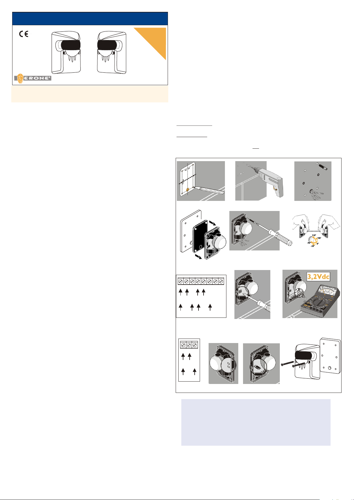
1 - Individuare la posizione dei 6 fori di fissaggio per mezzo
della dima di foratura presente nella confezione (Fig. 1);
2 - Praticare i 4 fori per il fissaggio della base. (Diam del foro: 5 mm)
3 - Assemblare la guarnizione e la fotocellula ( Fig. 4)
4 - Posizionare i 4 tasselli in plastica;
5 - Posizionare la piastra di riscontro;
6 - Appoggiare sopra la piastra di riscontro il fondo della fotocellula, completo
di guarnizione ( fig. 4)
7 - Fissare la cellula per mezzo delle 4 viti in dotazione (Fig. 5);
8 - Eseguire i collegamenti elettrici ed alimentare ricevitore ( Fig. 7) e
trasmettitore ( Fig. 10);
- alim. 12 Vac/dc : Morsetti 0 - 12
- alim. 24 Vac/dc : Morsetti 0 - 24.
9 - Dopo aver eseguito l’allineamento ( Fig. 6) e le regolazioni ( Fig. 8)
( Vedere paragrafo successivo), fissare il coperchio di alluminio per mezzo delle
2 viti con testa speciale antivandalica in dotazione, facendo uso dell’attrezzo
contenuto nella confezione (Fig. 13).
Allineamento
Allineare il trasmettitore ed il ricevitore in modo che venga creato il fascio ed il
led rosso LR si spenga ( Fig. 6 - Fig. 11)).
Regolazione della sensibilità
Se la distanza tra il trasmettitore ed il ricevitore è inferiore a 5 metri, togliere il
ponticello sul trasmettitore ( Fig. 12 ).
Regolare la sensibilità azionando il potenziometro sul ricevitore( Fig. 8).
La regolazione ottimale si ottiene quando viene rilevata una tensione di 3,2 Vdc tra
i morsetti T e P ( tensione misurata con un voltmetro - Fig. 9 ).
Sul Trasmettitore
Il led verde si accende quando il trasmettitore viene alimentato.
Sul ricevitore
- il led verde si accende quando il ricevitore viene alimentato ( Fig. 11 );
- il led rosso è acceso quando ricevitore e trasmettitore non sono allineati (Fig. 11).
Emissione infrarossi con diodo: GaAlAs
Modulazione continua: 1,5 KHz
Lunghezza d’onda di emissione: 880 nm
Alimentazione: 12 - 24 Vac/dc
Consumo in 12 Vac/dc
- ricevitore: 34 mA
- trasmettitore: 45 mA
Consumo in 24 Vac/dc
- ricevitore: 34 mA
- trasmettitore: 42 mA
Doppio relé con scambi in serie: SI
Contatto di uscita: 1 NC / 1 NO
Potere di interruzione corrente continua: 24 W / 48 V
Potere di interruzzione corrente alternata: 60 VA / 48 V
Temperatura di funzionamento: -10°C /+55°C
Test point per la centratura.
Guarnizione per l'appoggio a parete in gomma termoplastica
Protezione del contenitore: IP55
Portata nominale in tutte le condizioni: 20 m
Dimensioni (mm): 98 x 68 x 51
Conformità: UNI8612
Marcatura: CE
ERONE è un marchio ELPRO INNOTEK S.p.A.
Via Piave, 23 - I-31020 S.Pietro di Feletto (TV) - ITALIA
Tel. 0438/450979 - Fax. 0438/457126
Numero Verde : 800.53.46.46
Web: www.erone.com
DI INSTALLAZIONE
ISTRUZIONI
FOTOCELLULE S20AV
SEF2420AV
Contenuto della confezione
Guarnizioni 2
Trasmettitore 1
Ricevitore 1
Coperchi in alluminio con vetrino 2
Viti fissaggio fotocellula 8
Viti speciali M5 per fissaggio coperchio 4
Tasselli plastici Ø5 8
Piastre di riscontro 2
Dima di foratura 1
Attrezzo speciale per viti M5 antivandalo 1
Sezione di cavo raccomandata:
2
-Cellula trasmittente 2 x 0,6 mm
2
-Cellula ricevente 4 x 0,6 mm .
Collegare il contatto di uscita ai morsetti C ed NO per un contatto normalmente
aperto oppure C ed NC per un contatto normalmente chiuso ( Fig. 7 ).
La garanzia è di 24 mesi dalla data di fabbricazione apposta
all’interno. Durante tale periodo, se l’apparecchiatura non
funziona correttamente, a causa di un componente difettoso,
essa verrà riparata o sostituita a discrezione del fabbricante.
La garanzia non copre l’integrità del contenitore plastico.
La garanzia viene prestata presso la sede del fabbricante.
GARANZIA
THE SMART LIVING
Vi ringraziamo per aver scelto un prodotto ERONE . Per un utilizzo più efficiente
della Vostra apparecchiatura si consiglia di leggere attentamente questo manuale.
Fig. 7 Fig. 8
Fig. 10
C NO NC +T. P.
12 Vac/dc
24 Vac/dc
N.A.
N.C.
Transmitter
Receiver
Fig. 9
24
12
0
12 Vac/dc
24 Vac/dc
2412
0
Fig. 1 Fig. 2 Fig. 3
Fig. 4
Fig. 5 Fig. 6
Fig. 11 Fig. 12
LV
LR
Fig. 13
Technical specifications
Description
Installation phases
Adjustment
LED states
On the transmitter
The green led is ON when the transmitter is powered.
On the receiver
- The green led is ON when the receiver is powered ( Fig. 11 );
- The red led is ON when the beam is not established (Fig. 11).
ERONE is a trademark by ELPRO INNOTEK S.p.A.
Via Piave, 23 - I-31020 S.Pietro di Feletto (TV) - ITALY
Tel. +39/0438/450979 - Fax. +39/0438/457126
Toll free number : 800.53.46.46
Web: www.erone.com
Fig. 7 Fig. 8
Fig. 10
C NO NC +T. P.
12 Vac/dc
24 Vac/dc
N.A.
N.C.
Transmitter
Receiver
Fig. 9
24
12
0
12 Vac/dc
24 Vac/dc
2412
0
INSTALLATION
NOTICES
INFRARED PHOTOCELLS S20AV
SEF2420AV
Packing list
Seals 2
Transmitter 1
Receiver 1
Aluminium covers 2
Photocell fixing screws 8
ISO M5 special screws for cover fixing 4
Plastic plugs Ø5 8
Fixing aluminium plates 2
Drilling template 1
Special tool for M5 antivandalic screws 1
Fig. 1 Fig. 2 Fig. 3
Fig. 4
Fig. 5 Fig. 6
The guarantee period of all Erone products is 24 months,
beginning from the manufacturer date. During this period, if
the product does not work correctly, due to a defective
component, the product will be repaired or substituted at the
discretion of the producer. The guarantee does not cover the
plastic container integrity. After-sale service is supplied at the
GUARANTEE
THE SMART LIVING
Thank you for your choice of a product ERONE. You are recommended to read
carefully this manual before tinstalling the product.
The infrared photocells ERONE mod. SEF2420AV are a security device designed to
the protection of areas in which are operating automatic closing systems.
The alluminium covers allows an antivandalic installation.
The product is composed by a couple of adjustable optic infrared devices TX and
RX, operating at 880 nm wavelength.
The rated range is 20 mt under all whether conditions ( rain, fog, dust ).
The reduced dimensions allow an easy installation procedure on any type of
structure.
The adjustable optic both horizontally ( ±40° ) and vertically (±15° ) allows the
best alignment in any installation condition.
Infrared emission with diode: GaAlAs
Continuous modulation: 1,5 KHz
Wavelength emission: 880 nm
Power supply: 12 - 24 Vac/dc
Current consumption at 12 Vac/dc
- receiver: 34 mA
- transmitter: 45 mA
Current consumption at 24 Vac/dc
- receiver: 34 mA
- transmitter: 42 mA
Double contact relay with serial exchange: yes
Output contacts: 1 NO / 1 NC
Max DC power on the relay contacts: 24 W / 48 V
Max AC power on the relay contacts: 60 VA / 48 V
Operating temperature: -10°C /+55°C
Best alignment test point.
Base plate in thermoplastic rubber.
IP Grade: IP55
Rated range in all conditions: 20 m
Dimensions (mm): 98x 68 x 51
Conformity according to: UNI8612
Marking: CE
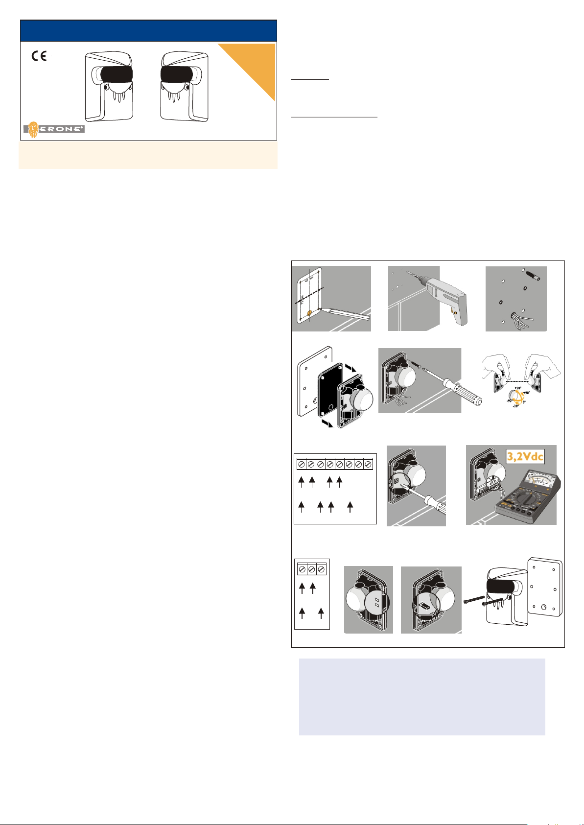
1 - Mark the location of the fixing holes using the drilling template supplied
with the photocells( Fig. 1);
2 - Drill the 4 fixing holes for the base. (Hole diam: 5mm);
3 - Locate the plugs provided 4 plastic (Fig. 3);
4 - Assemble the fixing plate the seal and the photocells (Fig. 4);
6 - Mount the photocell with the screws supplied (Fig. 5);
7 - Make the electrical connections and power the receiver
( Fig. 7) and the transmitter ( Fig. 10);
- 12 Vac/dc : terminals 0 - 12;
- 24 Vac/dc : terminals 0 - 24.
8 - After the alignment ( Fig. 6 ) and the adjustment ( Fig. 8), ( see next
paragraph) fit the cover using the special screws with anti-vandalic head
making use of the tool supplied (Fig. 13)
Recommended cable cross-section:
2
- transmitter photocells 2 x 0,6 mm
2
- receiver photocells 4 x 0,6 mm
Connect the output contact to the terminals C eand NO for a normally open
contact or C and NC for a normally closed contact ( Fig. 7 ).
Alignment
Align the transmitter and the receiver so that the beam is established and the red
led (LR) goes off ( Fig. 6 and Fig. 8 ).
Sensitivity adjustment
If the distance between the transmitter and the receiver is less than 5 metres remove
the bridge on the transmitter ( Fig. 12 ).
Adjust the sensitivity with the trimmer on the receiver ( Fig. 8 ).
The optimum detection is obtained when a voltage of 3,2 Vdc is read across
terminals T and P ( read the voltage with a voltmeter - Fig. 9).
Fig. 11 Fig. 12
LV
LR
Fig. 13

Caractéristiques
Description
Installation
Réglages
Etat des LED
ERONE est un produit ELPRO INNOTEK S.p.A.
Via Piave, 23 - I-31020 S.Pietro di Feletto (TV) - ITALY
Tel. +39/0438/450979 - Fax. +39/0438/457126
Toll free number : 800.53.46.46
Web: www.erone.com
INSTALLATION
NOTICES
INFRAROUGE CELLULES S20AV
SEF2420AV
Composition du kit
Joint d’étainchéité 2
Cellule émettrice (3 bornes ) 1
Cellule réceptrice ( 8 bornes ) 1
Aluminium capots 2
Vis de fixation cellule 8
ISO M5 Vis de fixation capot 4
Chevilles plastiques Ø5 8
Plaques de fixation 2
Gabarit de perçage 1
Outillage special pour les vis antivandales 1
La garantie porte sur une période de 24 mois pendant
laquelle, si l'appareil ne fonctionne pas normalement
du fait d'une pièce défectueuse, l'ensemble ou la pièce
sera, au choix de ELPRO INNOTEK, soit réparé, soit
remplacé.
La garantie ne couvre pas l’intégrité de l’enveloppe
GARANTIE
THE SMART LIVING
Merci d’avoir choisi un produit ERONE. Il vous est conseillé de lire attentivement
cette notice avant d’installer le produit
Raccorder le contact de sortie (fig. 7a):
- Contact NC : Bornes C - NF (contact normalement fermé)
- Contact NO : Bornes C - NO (contact normalement ouvert)
Les cellules photoélectriques à l'infrarouge ERONE mod. SEF2420AV sont
destinées à assurer la sécurité des biens et personnes lors du fonctionnement des
systèmes de fermeture automatique.
Le capot métallique en aluminium permet une installation antivandale.
Le système se compose de deux dispositifs à infrarouge émetteur- récepteur à
optique réglable.
La portée nominale est de 20 mètres quelles que soient les conditions de visibilité
(pluie, brouillard, poussiére).
Emission infrarouge avec diode: GaAlAs
Modulation continue: 1,5 KHz
Longueur d’onde de l’émission: 880 nm
Alimentation: 12 - 24 Vac/dc
Consommation à 12 Vac/dc
- le récepteur: 34 mA
- l’émetteur: 45 mA
Consommation à 24 Vac/dc
- le récepteur 34 mA
- l’émetteur: 42 mA
Double relayage avec é charges en séries: oui
Contact de sortie: 1 NF / 1 NO
Pouvoir de coupure en courant continu: 24 W / 48 V
Pouvoir de coupure en courant alternatif: 60 VA / 48 V
Température de fonctionnement: -10°C /+55°C
Joint d’étanchéité en gomme thermoplastique
Protection: IP55
Portée suivant conditions: 20 m
Encombrement (mm): 98 x 68 x 51
Conformité: UNI8612
Marquage: CE
1 - Repérer l’emplacement des trous de fixation à l’aide du gabarit de perçage
fourni avec les cellules (Fig.1);
2 - Percer les trous de fixation. (Ø5 mm ) (Fig.2);
3 - Mettre les chevilles en place ( plastiques et métalliques) (Fig.3);
4 - Assembler le joint d’étanchéité et la cellule(Fig.4);
5 - Fixer la cellule à l’aide des vis fournies (Fig.5);
6 - Procédér aux raccordements électriques et alimenter le récepteur ( Fig. 7) et
l’émetteur ( Fig. 10);
- alim. 12 Vac/dc : Bornes 0 - 12
- alim. 24 Vac/dc : Bornes 0 - 24.
7 - Après avoir procédé à l’alignement ( Fig. 6) et aux réglages ( Fig. 6), fixer le
capot métallique avec les vis antivandales fournies avec l'aide de l'outil;
Section de câble précognisée:
2
- Cellule émettrice 2 x 0,6 mm
2
- Cellule réceptrice 4 x 0,6 mm .
Alignement
Aligner l’émetteur et le récepteur de façon a ce que faise le faiceau soit établi et la
led rouge LR s’éteigne ( Fig. 6 ).
Réglage de la sensibilité
Si la distance entre l’émetteur et le récepteur est inférieure à 5 metres, retirer le
pont sur l’émetteur ( Fig. 11 ).
Régler la sensibilité en tournant le potentiométre sur le récepteur( Fig. 9).
La sensibilité optimum s’obtient quand une tension de 3,2 Vdc est relevée entre les
bornes T et P ( tension relevée avec l’aide d’un multimètre - Fig. 9 ).
Sur l’émetteur
La led verte est allumée quand l’émetteur est alimenté.
Sur le récepteur
- la led verte est allumée quand le récepteur est alimenté ( Fig. 10 ).
- la led rouge est allumée quand le récepteur et l’émetteur ne sont pas établis.
( Fig. 11 ).
Fig. 7 Fig. 8
Fig. 10
C NO NC +T. P.
12 Vac/dc
24 Vac/dc
N.A.
N.C.
Transmitter
Receiver
Fig. 9
24
12
0
12 Vac/dc
24 Vac/dc
2412
0
Fig. 1 Fig. 2 Fig. 3
Fig. 4
Fig. 5 Fig. 6
Fig. 11 Fig. 12
LV
LR
Fig. 13
Technische eigenschaften
Installation
ERONE ist ein Zeichen ELPRO INNOTEK S.p.A.
Via Piave, 23 - I-31020 S.Pietro di Feletto (TV) - ITALY
Tel. +39/0438/450979 - Fax. +39/0438/457126
Rufnummer zum Nulltarif : 800.53.46.46
Web: www.erone.com
Abb. 7 Abb. 8
Abb. 10
C NO NC +T. P.
12 Vac/dc
24 Vac/dc
N.A.
N.C.
Transmitter
Receiver
Abb. 9
24
12
0
12 Vac/dc
24 Vac/dc
2412
0
LICHTSCHRANKE S20AV
SEF2420AV
Packing list
2
1
1
ALUMINIUM DECKERS 2
BEFESTINGUNG SCHRAUBEN 8
ISO M5 BEFESTINGUNG SCHRAUBEN 4
EINSATZ KUNSTOFF Ø5 8
BOHRUNG SHILFE 1
WERKZEUG FUR ANTI-SABOTAGE SCHAUBEN1
DICHTUNG
SENDER
EMPFÄNGER
IS-FAVERML Rev. 2 del 04/11/2003
Abb. 1 Abb. 2 Abb. 3
Abb. 4
Abb. 5 Abb. 6
Die Garantie beträgt 24 Monaten vom inneren
angezeigten Herstellungsdatum . Während solcher
Periode, wenn das Gerät nicht korrekt wegen eines
defekten Bauelements arbeitet, wird es beseitigt oder
nach Hersteller Entscheidung ersetzt. Die Garantie
bedeckt die Integrität des plastischen Gehäuses nicht.
GARANTIE
THE SMART LIVING
Die Infrarotlichtschranken ERONE Typ SEF2420AV sind Geräte, um die
Sicherheit von Gütern und Leuten im Betrieb von automatischen
Schliessungssystemen zu schützen.
Das aluminium gehause erlaubt eine anti-sabotage anwendung.
Das System bestehet aus einem Paar von Infrarotvorrichtungen TX und
RX mit schwenkbarer Optik, die bei einer Wellenlänge von 880 nm arbeiten.
Die Nennreichweite ist gleich 20 Metern in allen Sichtverhältnissen (Regen,
Nebel, Staub).
Den Ausgangs-Kontakt (Bild 7a) verbinden:
-Kontakt NC: Klemmen C-NF (Kontakt normalerweise geschlossen)
-Kontakt NO: Klemmen C-NO (Kontakt normalerweise geoffnet)
Installationsanleitung
Wir danken Ihnen, um ein Produkt ERONE gewählt zu haben. Man empfiehlt
aufmerksam dieses Handbuch zu lesen, für eine leistungsfähigere Benutzung von
Beschreibung
Infrarotausstrahlung mit Diode: GaAlAs
Dauermodulation: 1.5 KHz
Wellenlänge der Ausstrahlung: 880 nm
Stromversorgung: 12-24 V Ws/Gs
Stromverbrauch bei 12 V Ws/Gs
-Empfänger: 34 mA
-Sender: 45 mA
Stromverbrauch bei 24 V Ws/Gs
-Empfänger: 34 mA
-Sender: 42 mA
Doppelrelais mit Austausch in Serie: Ya
Ausgangskontakt: 1 NC 1 NO
Abschaltleistung bei Gleichstrom: 24 W / 48 V
Abschaltleistung bei Wechselstrom: 60 VA / 48 V
Betriebstemperatur: -20 °C / +55 °C
Gehäusesschutzgrad: IP55
Nennreichweite unter allen Bedingungen: 20 Meter
Abmessungen 98 x 68 x 51 mm
Entsprechend: Vorschrift UNI8612
Zertifikat: CE
1 - Die Position der Befestigungsbohrungen mit der beigestellten
Bohrschablone anzeichnen ( Abb. 1);
2 - Die Befestigungsbohrungen herstellen ( Durchmesser : 5 mm ) (Abb. 2);
3 - Die beigestellten Dübel einsetzen (Abb. 3) ;
4 - Den Dichtungsring und die Fotozelle zusammenbauen(Abb. 4);
5 - Die Zelle mit den beigestellten Schrauben befestigen (Abb. 5);
6 - Die elektrischen Anschlüsse ausführen und den Empfänger (Abb. 7) und
das Übertragungsgerät (Abb 10) stromversongen;
- Verbrauch 12 Vac/dc : Klemmen 0 - 12.
- Verbrauch 24 Vac/dc : Klemmen 0 - 24.
7 - Nach die Einstellungen (Abb. 13) die Glassplatte mit den beigestellten
Schrauben feststellen.
Empfohlner Kabelquerschnitt:
2
-Sendzelle 2 x 0,6 mm
2
-Empfangszelle 2 x 0,6 mm .
Ausrichtung
Den Sender derart mit dem Empfänger ausrichten dass ein Strahlenbündel gebildet
wird.Die rote Led LR wird gelöscht (Abb. 4).
Empfindlichkeitseinstellung
Wenn der Abstand zwischen dem Sender und dem Empfänger unter 5 Metern liegt,
die Brücke entfernen
(Abb. 6 ). Die Empfindlichkeit am Potentiometer P1 einstellen ( Abb. 5).
Bei der optimalen Einstellung Beträgt die Spannung zwischen den klemmen T un P
3,2 Vdc ( mit einem Voltmeter zu messen - Abb.3 ).
Einstellung
Am Sender
- Die grüne Led schaltet sich ein, wenn der Sender stromversorgt wird.
Am Empfänger
- Die grüne Led schaltet sich ein, wenn der Empfänger stromversorgt wird.
- Die rote Led schaltet sich ein, wenn Sender und Empfänger nicht korrekt
ausgerichtet sind.
LED-Zustände
Bild. 11 Bild. 12
LV
LR
Bild. 13
Table of contents
Languages:
Popular Security Sensor manuals by other brands


Pittway
Pittway System Sensor WFDT Installation and maintenance instructions

Stanley
Stanley LD200 manual

LEGRAND
LEGRAND 0 884 09 quick start guide

Mitsubishi Electric
Mitsubishi Electric MP-EG-TS-V2 Technical manual

Southwest Microwave
Southwest Microwave INTREPID Technical manual

Det-Tronics
Det-Tronics X3301 instructions


