13052-S01 Rev C 11/8/2011
Page 2 of 5
Operation
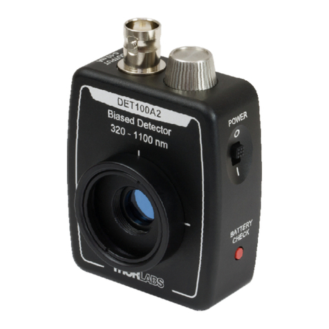
Thorlabs DET series are ideal for measuring both pulsed and CW light sources. The DET10A includes a reverse-
biased PIN photo diode, bias battery, and ON/OFF switch packaged in a rugged housing. The BNC output signal is
the direct photocurrent out of the photo diode anode and is a function of the incident light power (P) and wavelength
(λ). The Spectral Responsivity, ℜ(λ), can be obtained from Figure 1 to estimate the amount of photocurrent to
expect. Most users will wish to convert this photocurrent to a voltage (V
OUT
) for viewing on an oscilloscope or DVM.
This is accomplished by adding an external load resistance, R
LOAD
. The output voltage is derived as:
V
OUT
= P * ℜ(λ) * R
LOAD
It should be noted that the load resistor will react with the photodetector junction capacitance (C
J
) to limit the
bandwidth. For best frequency response, a 50Ωterminator should be used. The bandwidth (f
BW
) and the rise-time
response (t
R
) can be approximated using the diode capacitance (C
J
) and the load resistance (R
LOAD
) as shown below:
f
BW
= 1 / (2 * π* R
LOAD
* C
J
)
t
R
= 0.35 / f
BW
For maximum bandwidth, we recommend using a 50Ωcoax cable with a 50Ωterminating resistor at the opposite end
of the coax. This will also minimize ringing by matching the coax with its characteristic impedance. If bandwidth is not
important, you may increase the amount of voltage for a given input light by increasing the R
LOAD
.
BATTERY
ON/OFF
1K
R
0.1uF
C
2
BNC
RLOAD
DIODE
PROTECTION
+
SWITCH
NOISE
FILTER
VBIAS
VBIAS
PHOTO
DETECTOR
VOLTAGE
REGULATOR
5V
VBAT
VOUT
Figure 2 – Circuit Schematic
Setup
•Unpack the optical head, install a Thorlabs TR-series ½” diameter post into one of the #8-32 (M4 on /M version)
tapped holes, located on the bottom and side of the sensor, and mount into a PH-series post holder.
•Attach a 50Ωcoax cable (i.e. RG-58U) to the output of the DET. Select and install a terminating resistor to the
remaining end of the cable and connect to a voltage measurement device. See the ‘Operation’ Section to
determine resistor values. Thorlabs sells a 50Ωterminator (T4119) for best frequency performance and a
variable terminator (VT1) for output voltage flexibility. Note the input impedance of your measurement device
since this will act as a terminating resistor. A load resistor is not necessary when using current measurement
devices.
•Power the DET on using the power switch. To check battery voltage, see ‘Battery Check’ below.
•Install any desired filters, optics, adapters, or fiber adapters to the input aperture. Caution: The DET10A was
designed to allow maximum accessibility to the photodetector by having the front surface of the diode flush with
the outside of the DET housing. When using fiber adapters, make sure that the fiber ferrule does not crash into
the detector. Failure to do so may cause damage to the diode and / or the fiber. An easy way to accomplish this
is to install a SM1RR retaining ring (included with the DET10A) inside the 1” threaded coupler before installing
the fiber adapter
•Apply a light source to the detector.
Battery Check and Replacement
Battery Check
Thorlabs new DET series includes a battery check feature that will allow the user to monitor the bias voltage on the
output BNC. Simply hold down the “VBIAS OUT” bottom located on the bottom edge of the unit. The bias voltage will
be output to the BNC. If a high impedance load is used (>10kΩ), the output will be equal to the bias voltage. This
feature includes a 1.05kΩcurrent limiting resistor (R
CL
) to prevent excessive loading of the battery if using small
terminating resistors. For example, a 50Ωload resistor with a 10V bias will produce a 200mA current without this
resistor. This will significantly decrease lifetime of the battery. The output bias voltage will be dependent on the load
resistor as described below. The A23 battery voltage characteristics show that the charge level is almost depleted as
