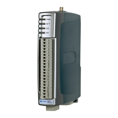
Elpro Technologies 915U-2 User manual

ELPRO Technologies, 9/12 Billabong Street, Stafford Qld, 4053 Australia.
Tel: +61 7 33528600 Fax: +61 7 33528677 Email: sales@elprotech.com
Web: www.elprotech.com
ELPRO Support Help-line America (866) 7134409 Rest of the world +617 3352 8624
V1.1.5
915U-2 Wireless I/O
User Manual

915U-2 Wireless I/O Page 1
Page 1 User Manual
Thank you for your selection of the 915U-2 I/O Module. We trust it will give you many years
of valuable service.
ATTENTION!
Incorrect termination of supply wires may cause internal damage and will void warranty. To
ensure your 915U-2 module enjoys a long life, double check ALL your connections with the
user manual before turning the power on.
CAUTION:
To comply with FCC RF Exposure requirements in section 1.1310 of the FCC Rules,
antennas used with this device must be installed to provide a separation distance of at
least 20 cm from all persons to satisfy RF exposure compliance.
Avoid:
•Operating the transmitter when someone is within 20 cm of the antenna
•Operating the transmitter unless all RF connectors are secure and any open
connectors are properly terminated
•Operating the equipment near electrical blasting caps or in an explosive atmosphere
All equipment must be properly grounded for safe operations.
All equipment should be serviced only by a qualified technician
SAFETY Notice:
Exposure to RF energy is an important safety consideration. The FCC has adopted a
safety standard for human exposure to radio frequency electromagnetic energy emitted by
FCC regulated equipment as a result of its actions in Docket 93-62 and OET Bulletin 65
Edition 97-01.

915U-2 Wireless I/O Page 2
Page 2 User Manual
Industry Canada:
This Class [A] digital apparatus complies with Canadian ICES-003.
This device complies with Industry Canada license-exempt RSS standard(s).
Operation is Subject to the following two conditions:
(1) This device may not cause interference,
(2) This device must accept any interference, including interference that may cause
undesired operation of the device.
This radio transmitter “915U-2” has been approved by Industry Canada to operate with the
antenna types listed below with the maximum permissible gain and required antenna
impedance for each antenna type indicated. Antenna types not included in this list, having
a gain greater than the maximum gain indicated for that type, are strictly prohibited for use
with this device.
Manufacturer
Model Number
Coax Kit
Net
ELPRO
SG-900-6
CC10/900
5dBi Gain
ELPRO SG-900-6 CC20/900 2dBi Gain
ELPRO SG-900EL CC10/900 2dBi Gain
ELPRO SG-900EL CC20/900 -1dBi Loss
ELPRO
YU6/900
CC20/900
4dBi Gain
ELPRO
CFD890EL
Includes 5m Cellfoil
Unity Gain
ELPRO
DG900-1
Includes 1m Cellfoil
-2dBi Loss
ELPRO
DG900-5
Includes 5m Cellfoil
-3dBi Loss
GNU Free Documentation Licence:
Copyright (C) 2009 ELPRO Technologies.
ELPRO Technologies is using a part of Free Software code under the GNU General Public
License in operating the “915U-2” product. This General Public License applies to most of
the Free Software Foundation’s code and to any other program whose authors commit by
using it. The Free Software is copyrighted by Free Software Foundation, Inc. and the
program is licensed “As is” without warranty of any kind. Users are free to contact ELPRO
Technologies at the following Email Address:sales@elprotech.com for instructions on how
to obtain the source code used for the 915U-2.
A copy of the license is included in “GNU Free Document Licence” at the end of the
manual.

915U-2 Wireless I/O Page 3
Page 3 User Manual
FCC Notice:
This 915U-2 module uses the “E2_900M Wireless Data Modem” radio and complies with
Part 15.247 of the FCC Rules.
Operation is subject to the following two conditions:
•This device may not cause harmful interference
•This device must accept any interference received, including interference that
may cause undesired operation.
915U-2 Radio Telemetry Unit must be installed in a suitable enclosure that provides
mechanical, shock and fire hazard protection.
This device must be operated as supplied by ELPRO. Any changes or modifications made
to the device without the written consent of ELPRO may void the user’s authority to operate
the device.
This device must be installed by professional installers in compliance with 47 CFR Part 15
Subpart C Section 15.204 and 15.205, who will be responsible for maintaining EIRP no
greater than 36 dBm in accordance with 47 CFR Part 15 Subpart C Section 15.247 (b)(2)(4).
In accordance with 47 CFR Part 15 Subpart C Section 15.204 only the following
antenna/coax cable kits combinations can be used.
Manufacturer
Model Number
Coax Kit
Net
ELPRO
SG-900-6
CC10/900
5dBi Gain
ELPRO SG-900-6 CC20/900 2dBi Gain
ELPRO SG-900EL CC10/900 2dBi Gain
ELPRO SG-900EL CC20/900 -1dBi Loss
ELPRO
YU6/900
CC20/900
4dBi Gain
ELPRO
CFD890EL
Includes 5m Cellfoil
Unity Gain
ELPRO
DG900-1
Includes 1m Cellfoil
-2dBi Loss
ELPRO
DG900-5
Includes 5m Cellfoil
-3dBi Loss
•Part 15 –This device has been tested and found to comply with the limits for a Class
B digital device, pursuant to Part15 of the FCC rules (Code of Federal Regulations
47CFR Part 15). Operation is subject to the condition that this device does not cause
harmful interference.
•Notice – Any changes or modifications not expressly approved by ELPRO could void
the user’s authority to operate this equipment.
This Device should only be connected to PCs that are covered by either FCC DoC or are
FCC certified.

915U-2 Wireless I/O Page 4
Page 4 User Manual
Hazardous Location Notices:
This device complies with
Ex nL IIC. T4A -40 C <= Ta <= +60 C
II 3G
WARNING: EXPLOSION HAZARD.
Do not disconnect equipment unless power has been switched off or the area
is known to be non-hazardous.
This equipment is suitable for use in Class I, Division 2, Groups A, B, C and D;
Tamb -40˚C to +60˚C or non-hazardous locations only.

915U-2 Wireless I/O Page 5
Page 5 User Manual
IMPORTANT Notice:
ELPRO products are designed to be used in industrial environments, by experienced
industrial engineering personnel with adequate knowledge of safety design considerations.
ELPRO radio products are used on unprotected license-free radio bands with radio noise
and interference. The products are designed to operate in the presence of noise and
interference, however in an extreme case, radio noise and interference could cause product
operation delays or operation failure. Like all industrial electronic products, ELPRO products
can fail in a variety of modes due to misuse, age, or malfunction. We recommend that users
and designers design systems using design techniques intended to prevent personal injury
or damage during product operation, and provide failure tolerant systems to prevent
personal injury or damage in the event of product failure. Designers must warn users of the
equipment or systems if adequate protection against failure has not been included in the
system design. Designers must include this Important Notice in operating procedures and
system manuals.
These products should not be used in non-industrial applications, or life-support systems,
without consulting ELPRO first.
•A radio license is not required in some countries, provided the module is installed
using the aerial and equipment configuration described in the 915U-2 Installation
Guide. Check with your local distributor for further information on regulations.
•Operation is authorized by the radio frequency regulatory authority in your country on
a non-protection basis. Although all care is taken in the design of these units, there is
no responsibility taken for sources of external interference. Systems should be
designed to be tolerant of these operational delays.
•To avoid the risk of electrocution, the aerial, aerial cable, serial cables and all
terminals of the 915U-2 module should be electrically protected. To provide maximum
surge and lightning protection, the module should be connected to a suitable earth
and the aerial, aerial cable, serial cables and the module should be installed as
recommended in the Installation Guide
•To avoid accidents during maintenance or adjustment of remotely controlled
equipment, all equipment should be first disconnected from the 915U-2 module
during these adjustments. Equipment should carry clear markings to indicate remote
or automatic operation. E.g. "This equipment is remotely controlled and may start
without warning. Isolate at the switchboard before attempting adjustments."
•The 915U-2 module is not suitable for use in explosive environments without
additional protection.
•The 915U-2 operates unlicensed Radio frequencies and proprietary protocols to
communicate over the radio. Nevertheless, if your system is not adequately secured,
third parties may be able to gain access to your data or gain control of your
equipment via the radio link. Before deploying a system make sure you have
considered the security aspects of your installation carefully.

915U-2 Wireless I/O Page 6
Page 6 User Manual
Limited Lifetime Warranty, Disclaimer, and Limitation of
Remedies
ELPRO products are warranted to be free from manufacturing defects for the “serviceable
lifetime” of the product. The “serviceable lifetime” is limited to the availability of electronic
components. If the serviceable life is reached in less than three years following the original
purchase from ELPRO, ELPRO will replace the product with an equivalent product if an
equivalent product is available.
This warranty does not extend to:
•Failures caused by the operation of the equipment outside the particular product's
specification, or
•Use of the module not in accordance with this User Manual, or
•Abuse, misuse, neglect or damage by external causes, or
•Repairs, alterations, or modifications undertaken other than by an authorized Service
Agent.
ELPRO liability under this warranty is limited to the replacement or repair of the product.
This warranty is in lieu of and exclusive of all other warranties. This warranty does not
indemnify the purchaser of products for any consequential claim for damages or loss of
operations or profits and ELPRO is not liable for any consequential damages or loss of
operations or profits resulting from the use of these products. ELPRO is not liable for
damages, losses, costs, injury or harm incurred as a consequence of any representations,
warranties or conditions made by ELPRO or its representatives or by any other party, except
as expressed solely in this document.

915U-2 Wireless I/O Page 7
Page 7 User Manual
TABLE OF CONTENTS
CHAPTER 1 - INTRODUCTION..........................................................................................12
1.1 Overview ......................................................................................................................................................12
1.2 Module Structure.........................................................................................................................................14
1.3 Getting Started ............................................................................................................................................15
CHAPTER 2 - INSTALLATION...........................................................................................16
2.1 General.........................................................................................................................................................16
2.2 Power/Supply...............................................................................................................................................16
2.2.1 Requirements.........................................................................................................................................16
2.2.2 Expansion I/O Supply ............................................................................................................................18
2.2.3 Internal I/O .............................................................................................................................................18
2.2.4 Grounding ..............................................................................................................................................19
2.3 Radio ............................................................................................................................................................20
2.3.1 900 MHz Spread Spectrum radio ..........................................................................................................20
2.3.2 Meshing capability .................................................................................................................................20
2.4 Antenna........................................................................................................................................................21
Dipole and Collinear antennas. ..................................................................................................................23
Yagi antennas.............................................................................................................................................24
2.5 Connections.................................................................................................................................................25
2.5.1 Bottom panel connections .....................................................................................................................25
Ethernet port...............................................................................................................................................25
USB Device Port for configuration..............................................................................................................25
RS-232 port ................................................................................................................................................25
RS-485 port with Modbus Support. ............................................................................................................25
2.5.2 Side Access Configuration Panel ..........................................................................................................26
“Factory Boot” switch..................................................................................................................................26
USB Host port.............................................................................................................................................27
Dipswitches.................................................................................................................................................27
Front panel connections .............................................................................................................................28
2.5.3 Digital Inputs ..........................................................................................................................................29
2.5.4 Pulsed Inputs .........................................................................................................................................30
2.5.5 Digital Outputs (Pulsed Outputs) ...........................................................................................................31
Digital Output Fail Safe Status ...................................................................................................................31
2.5.6 Analog Inputs.........................................................................................................................................33
Differential Current Inputs (AIN 1 & 2 only)................................................................................................33
Single Ended Current Inputs (AIN 3 & 4 only)............................................................................................34
Single Ended Voltage Inputs......................................................................................................................35
2.5.7 Analog Outputs ......................................................................................................................................36
CHAPTER 3 - OPERATION................................................................................................37
3.1 Overview ......................................................................................................................................................37
3.2 Indications ...................................................................................................................................................37
3.2.1 Front Panel Indications..........................................................................................................................37

915U-2 Wireless I/O Page 8
Page 8 User Manual
3.2.2 Boot Sequence “PWR” LED Indications................................................................................................37
3.2.3 Input / Output Indications.......................................................................................................................38
Digital Inputs...............................................................................................................................................38
Digital Outputs............................................................................................................................................38
Analog Inputs..............................................................................................................................................38
Analog Outputs...........................................................................................................................................38
3.2.4 Ethernet Indications ...............................................................................................................................39
3.3 System Design.............................................................................................................................................40
3.3.1 Radio Channel Capacity........................................................................................................................40
3.3.2 Dual Band Operation .............................................................................................................................40
3.3.3 Radio Path Reliability.............................................................................................................................40
3.3.4 Design for Failures.................................................................................................................................41
3.3.5 Indicating a Communications Problem..................................................................................................42
Fail-to-transmit alarm..................................................................................................................................42
Fail-to-receive alarm...................................................................................................................................42
3.3.6 WIBNet – Communication Registers. ....................................................................................................42
3.3.7 Testing and Commissioning...................................................................................................................43
3.4 WIBMesh ......................................................................................................................................................43
CHAPTER 4 - CONFIGURATION.......................................................................................44
4.1 First time Configuration .............................................................................................................................44
4.1.1 Default IP Address.................................................................................................................................44
4.1.2 Changing PC Network Settings .............................................................................................................44
4.1.3 Over the Air Configuration .....................................................................................................................47
4.2 Module Configuration.................................................................................................................................48
4.2.1 Software & Connections ........................................................................................................................48
4.2.2 Mappings ...............................................................................................................................................49
Write Mapping.............................................................................................................................................49
Gather Scatter Mapping .............................................................................................................................49
Read Mappings...........................................................................................................................................49
4.2.3 Address Map..........................................................................................................................................50
4.2.4 Standard 915U-2 I/O (Basic I/O)............................................................................................................51
4.2.5 I/O Configuration....................................................................................................................................51
Digital Inputs...............................................................................................................................................51
Digital Outputs............................................................................................................................................52
Pulsed Outputs...........................................................................................................................................52
Analog Inputs..............................................................................................................................................52
Analog Outputs...........................................................................................................................................53
4.2.6 Serial Expansion I/O..............................................................................................................................53
Adding modules..........................................................................................................................................53
115S Expansion I/O Memory Map..............................................................................................................54
Adding Expansion I/O to Configuration Software.......................................................................................54
4.2.7 Failsafe Blocks.......................................................................................................................................55
“Invalid” register state.................................................................................................................................56
4.2.8 Sensitivity Blocks...................................................................................................................................56
4.2.9 Serial Configuration ...............................................................................................................................58
Modbus TCP to RTU Gateway...................................................................................................................58
Expansion I/O.............................................................................................................................................58
4.2.10 Modbus Configuration..........................................................................................................................59
4.3 Web based Configuration...........................................................................................................................62
4.3.1 Mesh ......................................................................................................................................................62
4.3.2 IP Routing ..............................................................................................................................................64

915U-2 Wireless I/O Page 9
Page 9 User Manual
4.3.3 Radio Settings........................................................................................................................................65
4.3.4 Mesh Fixed Routes................................................................................................................................66
Example #1.................................................................................................................................................66
Example #2.................................................................................................................................................67
4.3.5 Module Information Web Page ..............................................................................................................69
4.3.6 System Tools Web page........................................................................................................................70
System Log File..........................................................................................................................................70
Reading Configuration File.........................................................................................................................70
Writing Configuration File ...........................................................................................................................70
Firmware Upgrade – Web Page.................................................................................................................70
Firmware Upgrade – USB ..........................................................................................................................70
Product Reconfiguration.............................................................................................................................72
4.3.7 Feature Licence Keys Web Page ..........................................................................................................73
CHAPTER 5 - DIAGNOSTICS ............................................................................................74
5.1 IO Diagnostics .............................................................................................................................................74
Modbus Error Registers..................................................................................................................................75
5.2 Connectivity (WibMesh) .............................................................................................................................75
LQI (Link Quality Indication).......................................................................................................................76
5.3 Neighbour List (WibMesh)..........................................................................................................................77
5.4 Neighbour RSSI (WibMesh)........................................................................................................................77
5.5 Network Diagnostics (WibMesh) ...............................................................................................................79
Ping.............................................................................................................................................................79
Trace Route................................................................................................................................................80
5.6 Network Statistics (WibMesh)....................................................................................................................81
5.7 Monitor Comms...........................................................................................................................................83
5.7.1 WibMesh – Monitor Radio Comms........................................................................................................83
5.7.2 WibMesh - Monitor IP Comms...............................................................................................................84
5.7.3 WibNet – Monitor Comms......................................................................................................................85
5.8 Statistics (WibMesh & WibNet)..................................................................................................................87
CHAPTER 6 - SPECIFICATIONS .......................................................................................88
6.1 Specifications..............................................................................................................................................88
APPENDIX A: DBM TO MW CONVERSION TABLE .......................................................90
APPENDIX B: I/O STORE REGISTERS........................................................................... 91
6.1.1 “Output Coils”.........................................................................................................................................91
6.1.2 “Input Bits”..............................................................................................................................................91
6.1.3 “Input Registers” ....................................................................................................................................92
6.1.4 “Holding Registers”................................................................................................................................93
APPENDIX C: EXPANSION I/O STORE REGISTERS.....................................................95
6.1.5 I/O store for a 115S-11 Expansion I/O module......................................................................................95
6.1.6 I/O store for a 115S-12 Expansion I/O module......................................................................................96

915U-2 Wireless I/O Page 10
Page 10 User Manual
6.1.7 I/O store for a 115S-13 Expansion I/O module......................................................................................96
APPENDIX D: MODBUS ERROR CODES.......................................................................97
APPENDIX E: MODULE I/O REGISTERS........................................................................ 98
6.1.8 115S Serial Expansion Modules I/O Registers....................................................................................100
6.2 GNU Free Document Licence...................................................................................................................102

915U-2 Wireless I/O Page 11
Page 11 User Manual
TABLE OF FIGURES
Figure 1 – Module Structure................................... 14
Figure 2 – Power Connectors ................................ 16
Figure 3 – Supply Connections.............................. 16
Figure 4 – Expansion I/O power & RS485............. 18
Figure 5 - Earthing ................................................. 19
Figure 6 -Wrapping Coax Connections.................. 22
Figure 7 – Collinear Antenna mounting ................. 23
Figure 8 - Yagi Antenna Mounting ......................... 24
Figure 9 – Bottom Panel Connections ................... 25
Figure 10 – RS485 Connections............................ 26
Figure 11 – Side Access Panel.............................. 26
Figure 12 – Front Panel Connections .................... 28
Figure 13 – Digital Input Wiring.............................. 29
Figure 14 – Pulsed Input Wiring............................. 30
Figure 15 – Digital Output Wiring........................... 31
Figure 16 – Digital Output Failsafe Times.............. 32
Figure 17 - Fail-Safe State..................................... 32
Figure 18 – Differential Current Inputs................... 33
Figure 19– Single Ended Current Inputs................ 34
Figure 20 – Voltage Inputs..................................... 35
Figure 21 – Analog Outputs................................... 36
Figure 22 - Boot Sequence.................................... 37
Figure 23 – Network Settings................................. 45
Figure 24 - Ping...................................................... 45
Figure 25 – Main Welcome Screen........................ 46
Figure 26 -Over the air Configuration .................... 47
Figure 27 - Installation............................................ 48
Figure 28 – Configuration Software ....................... 48
Figure 29 - Mappings............................................. 49
Figure 30 - Gather/Scatter Mapping ...................... 50
Figure 31 - Expansion I/O...................................... 55
Figure 32 - Failsafe Block ...................................... 55
Figure 33- Invalid Register State............................56
Figure 34 - Modbus TCP/RTU................................58
Figure 35 - Expansion I/O.......................................59
Figure 36 - Modbus Master.....................................60
Figure 37 - Mesh Configuration ..............................62
Figure 38 - IP Routing.............................................64
Figure 39 – Radio Configuration Screen ................65
Figure 40 - Mesh Fixed Route #1 ...........................67
Figure 41 - Mesh Fixed Route#2 Routing Rules ....67
Figure 42 - Mesh Fixed Route #2 ...........................67
Figure 43 – Mesh Fixed Route #2 Routing Rules...68
Figure 44 – Module Information..............................69
Figure 45 – System Tools.......................................70
Figure 46 - Firmware Upgrade LED Indications .....71
Figure 47 - Product Reconfiguration.......................72
Figure 48 - Feature License Keys...........................73
Figure 49- I/O Diagnostics......................................74
Figure 50 - Connectivity..........................................75
Figure 51 – Neighbour List......................................77
Figure 52 - Neighbour RSSI....................................77
Figure 53 - Multipath Fading...................................78
Figure 54 – Network Diagnostics............................79
Figure 55 – Trace Route.........................................80
Figure 56 – Network Statistics Period.....................81
Figure 57 – Network Statistics................................81
Figure 58 – Hourly Statistics...................................82
Figure 59 –Daily/Weekly Statistics .........................82
Figure 60 - Monitor Comms....................................83
Figure 61 - IP Communication monitoring ..............84
Figure 62 - WibNet Monitor Comms .......................85
Figure 63 – Module Statistics..................................87

Page 12 915U-2 Wireless I/O
Page 12 User Manual
Chapter 1 - Introduction
1.1 Overview
The 915U-2 range of I/O modules has been designed to provide standard “off-the-shelf”
telemetry functions, for an economic price. Telemetry is the transmission of data or
signals over a long distance via radio or twisted-pair wire cable.
Although the 915U-2 Series is intended to be simple in its application, it provides many
sophisticated features, which will be explained in the following chapters.
This manual should be read carefully to ensure that the modules are configured and
installed to give reliable performance.
The 915U-2 telemetry module extends the functionality provided by the earlier 105U
and 905U E-series modules. It provides on-board I/O via a front mounting 20-way
connector and has provision for extra expansion modules (ELPRO 115S or MODBUS
devices) to be connected using a standard RS485 serial connection.
The module can monitor the following types of signals
•Digital (on/off) signals - Contact Closure or Switch
•Analog (continuously variable) signals – Tank level, Motor speed, temperature,
etc
•Pulsed signal - Frequency signal – Metering, accumulated total, rainfall, etc
•Internal Signals – Supply voltage, Supply failure, battery status, etc.
The modules monitor the input signals and transmit the values by radio or Ethernet
cabling to another module or modules that have been configured to receive this
information.
The 915U-2 radio has been designed to meet the requirements of unlicensed operation
for remote monitoring and control of equipment. A radio licence is not required for the
915U-2 in many countries.
Input signals that are connected to the module are transmitted and appear as output
signals on other modules. A transmission occurs whenever a "Change-of-State”, “COS”
occurs on an input signal. A "Change-of-State" of a digital or an internal digital input is a
change from "off" to "on" or vice-versa.
For an analog input, internal analog input or pulse input rate a "Change-of-State" is a
configurable value called “Sensitivity”. The default Sensitivity is 1000 counts (3%) but
can be changed in the Sensitivity Block page.
In addition to change-of-state messages, update messages are automatically
transmitted on a configurable time basis. This update ensures the integrity of the
system.
Pulse inputs counts are accumulated and the total count is transmitted regularly
according to the configured update time.

915U-2 Wireless I/O Page 13
Page 13 User Manual
The 915U-2 modules transmit the input/output data using radio or Ethernet. The data
frame includes the "address" of the transmitting module and the receiving module, so
that each transmitted message is acted on only by the correct receiving unit. Each
message includes error checking to ensure that no corruption of the data frame has
occurred due to noise or interference. The module with the correct receiving "address"
will acknowledge the message with a return transmission (acknowledgement). If the
original module does not receive a correct acknowledgement, it will retry 1 to 5 times
(default is 3) before setting the communications fail status of that message. For critical
messages, this status can be reflected on an output on the module for alert purposes.
The module will continue to try to establish communications and retry, each time an
update or change-of-state occurs.
A system can be a complex network or a simple pair of modules. An easy-to-use
configuration procedure allows the user to specify any output destination for each input.
The 915U-2 comes from the factory with ELPRO WibMesh protocol as standard, this
protocol provides enhanced features, including IP addressing, allowing thousands of
modules to exist in a system, and allowing automatic routing of messages through
repeater stations.
The module can also be configured with the Legacy WibNet protocol which provides
operation with existing ELPRO wireless I/O devices (905 series and 105 series
modules). Please see separate WibNet configuration Supplement for details.
The module can easily be switched between the two versions by selecting the
appropriate protocol from an inbuilt web page.
Each 915U-2 radio can have up to 24 expansion I/O modules (ELPRO 115S) connected
by RS485 twisted pair provided there is sufficient power to power all modules with I/O.
Any input signal at any module may be configured to appear at any output on any
module in the entire system.
Modules can be used as repeaters to re-transmit messages on to the destination
module. Repeaters can repeat messages on the radio channel or from the radio
channel to the serial channel (and serial to radio). The meshing protocol will
automatically select other stations to act as repeaters if required (up to ten hops). Using
Legacy protocol, up to five repeater addresses may be configured for each input-to-
output link.
The units may be configured via Ethernet using a web browser or via USB port and
system configuration software. The software configuration is defined in Chapter 4 -
Configuration.
For web based configuration consult separate Web Page configuration Supplement.

Page 14 915U-2 Wireless I/O
Page 14 User Manual
1.2 Module Structure
IO STORE
Discrete Outputs (00001)
Discrete Inputs (10001)
Word Inputs (30001)
Word Outputs (40001)
Long Inputs (36001)
Float Inputs (38001)
Long Outputs (46001)
Float Outputs (48001)
I/O Expansion Port
On Board I/O
8 x DIO
2 x DIFF AIN
2 x Single Ended AIN
2 X AOT
Various Internal I/O
RADIO INTERFACE
915U-2
Ethernet Port
Figure 1 – Module Structure
The 915U-2 is made up of a number of basic sections, which all interface with a central
Input and output storage area (I/O Store).
The I/O Data Store provides storage for I/O data as well as providing services to other
processes in the system. The I/O Store provides eight different blocks of data - two
containing input and output bit data, two containing input and output word data, two
containing long-word type data and two containing floating-point data. The two files of
each type in turn support inputs and outputs on the local machine, and data storage for
the gateway function of the machine. These files are mapped into the address map as
described below. There are other registers values within the database that can be used
for system management - these will be discussed later in this manual.
The Radio Interface allows the 915U-2 to communicate with other modules within the
system using a proprietary radio protocol called “WIBMesh”. Messages from other
915U-2 modules are received by the radio port and used to update the input values in
the I/O Data Store. The WIBMesh protocol is an extremely efficient protocol for radio
communications. Radio messages can be sent using exception reporting - that is, when
there is a change of an input signal - or by read/write messages. Each message will be
comprised of multiple I/O values termed as a “block” of I/O). There are also update
messages, which are sent for integrity purposes.
Messages allow error checking, with the destination address sending a return
acknowledgment. Up to four attempts are made to transmit the message over each hop
of the radio path, if no acknowledgement is received. The WIBMesh protocol is
designed to provide reliable radio communications on an open license-free radio
channel.
The On-Board I/O in the form of - 8 discrete I/O, 2 single ended analog inputs, 2
differential analog inputs, and 2 current sourcing analog outputs. Each discrete I/O can
function as either a discrete input (voltage free contact input) or discrete output

915U-2 Wireless I/O Page 15
Page 15 User Manual
(transistor output). Each I/O point is linked to separate I/O registers within the I/O Data
Store.
There are also a number of Internal I/O that can be accessed from the I/O Data Store.
These inputs can be used to interpret the status of a single module or an entire system
•Battery voltage – The battery terminal voltage displayed as an Analog value.
•Loop Supply – Monitors the +24V DC Analog Loop Supply (ALS), used to power
analog current loops and displays this as an Analog value.
•Expansion Module Volts – Monitors the Supply voltage of the connected
expansion modules, displayed as an Analog value.
•RSSI – Will indicate the radio signal level for the selectable address, displayed
as a dB level. Note: Only available in Legacy version. Otherwise, refer to
Communication diagnostics functions
•Comms Fail – A selectable register can indicate a Communications fail for a
particular message transmission.
The Expansion port, allows 115S expansion I/O modules to be added to the module.
Expansion I/O is dynamically added to the internal I/O of the 915U-2 by adding an offset
to the address.
1.3 Getting Started
Most applications for the 915U-2 require little configuration. The 915U-2 has many
sophisticated features, however if you do not require these features, this section will
allow you to configure the units quickly.
First, read Chapter 2 - “Installation”, which will go through the power supply,
antenna/coax connections and any I/O connections.
Power the 915U-2 and make an Ethernet connection to your PC (refer to Section 4.1
“First time Configuration”)
Configure the Ethernet Interface with an IP address that is compatible with your network
or computer via the Network Configuration webpage.
Save the configuration and the 915U-2 module is now ready to use. For an instruction
on configuration refer to Section 4.1 “Module Configuration”.

Page 16 915U-2 Wireless I/O
Page 16 User Manual
Chapter 2 - Installation
2.1 General
All 915U-2 Series modules are housed in a plastic enclosure with DIN rail mounting,
providing options for up to 14 I/O points, and separate power & communications
connectors. The enclosure measures 170 x 150 x 33 mm including connectors. The
antenna protrudes from the top
2.2 Power/Supply
EXPANSION SUPPLYETHERNET USB RS232
100M LINK GND BAT
+SUP
-SUP
+
B A - +
Figure 2 – Power Connectors
SUP -
SUP +
POWER SUPPLY
GND
BAT +
15-30V DC Supply
+
_
External “Sealed Lead
Acid” battery if required
Figure 3 – Supply Connections
2.2.1 Requirements
The recommended power options available for the 915U-2 module are as follows.
1. 15 - 30 volt DC power source rated at 37Watts, connected to the “SUP+” &
“SUP-” terminals.
2. 12-15 volt DC power source rated at 37Watts, connected to the “BAT+” & “GND”
terminals
A primary power supply connected to the “SUP+” & “SUP-” terminals will automatically
charge a 13.8V Sealed Lead-Acid battery, if connected to the “BAT+” and “GND”
terminals at up to 1Amp at ambient room temperature (25°C). Battery charge current is
reduced to 0.5A at 60°C.

915U-2 Wireless I/O Page 17
Page 17 User Manual
If utilising option 1 above and the Primary Supply fails the Battery Supply will continue
to power the module without interruption to the operation.
The Supply and Battery charging terminals are hosted on the 4-way connector on the
bottom edge of the module labelled “Supply”
Both Supply and Battery connections have reverse polarity and over voltage protection.
The power supply should be CSA Certified Class 2 approved for normal operation.
If the device is being used in a Class I Div 2 explosive area, the supply must have Class
I Div 2 approval.
When powering the module the power source must be able to provide enough current to
power all module operations, i.e. Quiescent current, Peak Transmit current, Digital and
Analog I/O including loop supply and Battery charging (if applicable).
To calculate the Power Supply current limit, use the following criteria.
Current
@ 13.8V
@ 24V
Quiescent Current of the module 200mA 115mA
Module Maximum I/O (4xAI, 2xAO, 8xDO) 500mA 290mA
Peak Transmit current 500mA 290mA
External Expansion I/O 1000mA 575mA
Battery charging 1000mA 575mA
The following table shows typical +24V Supply current limits with all module options.
Expansion I/O
No Expansion I/O
No Battery fitted
1270mA 695 mA
Battery fitted
1555mA 980 mA
The following table shows typical +13.8V Supply current limits with all module options.
Expansion I/O
No Expansion I/O
No Battery fitted
2200mA 1200 mA
Battery fitted
2700 mA 1700 mA
E.g. If a module is powered by a 24V DC supply and there is no backup battery
connected and it has expansion I/O fitted the minimum current needed is 1.3 Amps
@24V (32Watts).
This is allowing for 500mA Peak Transmit current and up to 1 Amp for expansion I/O

Page 18 915U-2 Wireless I/O
Page 18 User Manual
2.2.2 Expansion I/O Supply
To allow increased I/O Capacity, a second 4-way terminal labelled “Expansion I/O”
provides a +12 Volt supply (up to 1A) and RS485 communications for any 115S serial
expansion I/O modules.
BA-+
915U-2
BA-+
115S- XX
BA-+
115S- XX
Figure 4 – Expansion I/O power & RS485
As a guide when using the I/O power connection from the 915U-2, the number of I/O
modules is limited to three x 115S-11(using inputs), one x 115S-12, or one x 115S-13.
If more I/O Modules are required, you will need to calculate the overall current
consumption using the following criteria and power the modules from an external
supply.
115S Module Static Current drain = 120mA
115S Digital Inputs require 13mA per active input
115S Digital Outputs require 25mA per active output
115S Analog Inputs and Outputs require 50mA per I/O when operating at 20mA
E.g. a single 115S-11 using inputs only has a current consumption of approximately
320mA so you could connect up to three 115S-11 modules to the Expansion port
without overloading the on board I/O power supply.
A single 115S-12 using all analog inputs and digital outputs has a current consumption
of approximately 720mA so you could only connect one.
Keep in mind that when calculating the current consumption for the expansion I/O, the
maximum available current from the onboard power supply is 1 Amp. If the overall
Expansion I/O current consumption is over the 1 Amp maximum an external power
source will be required.
2.2.3 Internal I/O
The internal supply voltages can be monitored by reading the register locations below.
See Section 5.1 “IO Diagnostics” for details on how this can be done.
The values can also be mapped to a register or an analog output on another module
within the radio network.

915U-2 Wireless I/O Page 19
Page 19 User Manual
30005 Local Supply voltage (8-40V scaling)
30006 Local Battery voltage (8-40V scaling)
30007 Local 24V loop voltage (8-40V scaling) – Internally generated +24V
supply used for analog loop supply. Maximum Current limit is 100mA
30008 115S Supply Voltage (8-40V scaling)
38005 – 38008 Floating Point Registers, also indicate the Supply voltage, Battery
Voltage, +24V Supply and 115S Supply voltages but in a voltage
scale.
There are no dedicated discrete low voltage alarm indicators however each supply
voltage does have a High and a low Set point Status which can be used for this type of
alarm.
See section 0 “Analog Inputs” for details on how to configure these alarms.
2.2.4 Grounding
To provide maximum surge and lightning protection each module should be effectively
earthed / grounded via a "GND" terminal on the module – this is to ensure that the
surge protection circuits inside the module are effective. The module should be
connected to the same common ground or earth point as the enclosure “earth” and the
antenna mast “earth”.
The 915U-2 has a dedicated Earth connection screw on the bottom end plate next to
the Supply terminals. All EARTH wiring should be minimum 2mm² - 14 AWG
If using the 915U-2 with serial Expansion I/O modules then all expansion modules must
have a separate earth connection from the front terminal back to the common earth or
ground point. See Figure 5 - Earthing below
Figure 5 - Earthing
Other manuals for 915U-2
1
Table of contents
Other Elpro Technologies Gateway manuals
