ELPRO HS10M User manual

1
HDMI Matrix Switcher Series Rev. B May 18th 2015
ITEM NO.: HS10M 10 x 10 HDMI Matrix Switcher
HS10M is a 10x10 HDMI Matrix Switch that allows you to route 10 HD sources to 10 HD displays. The
10x10 HDMI Matrix switch is a complete HD routing solution for whole home HDTV systems. It provides
3D support, UltraHD 4K2K, and with 2U Rack mountable for professional installations. In addition, the
HS10M can be controlled through GUI Ethernet, Android/IOS App Control, IR remote control,
RS-232 and by the front panel keyboard.
Features:
Connect up to 10 HDMI source to 10 x HDMI display monitors.
HDMI 1.4 with 3D, HDCP and DVI Compliant.
High definition video up to 4K2K 24/25/30Hz 8bits, 1080p 60Hz 12bits.
Easy to use front panel control or IR remote control.
Built in Web server (GUI) and Android/iOS App Control.
Built in RS232 console port to select input/output and other parameters
Input/Output status could be displayed at front panel LCM and LED strings.

2
1.0 HS10M Panel View:
2.0 HS10M Connection View:
4
INPUT OUTPUT
…………… ……………
IR01
SOURCE
…………….. ……………..
HDMI 1
CONSOLE
RS-232
IR Receiver
PC
HDMI 10
TV
TV
HDMI 1
HDMI 10
SOURCE
MATRIX
RJ45
ETHERNET

3
3.0 Keypad, LEDs and LCM
3.1 Back Panel Switch:
POWER Light on Power on
Light off Power off
3.2 Front LED Indication:
ON BLUE Power on
RED Standby
LED off Power Off
INPUT 1~10 BLUE Signal indication
LED off No signal
OUTPUT 1~10 BLUE HDMI output indications
LED off Output unlink
Standby mode: The IR Remote controls only POWER on/off.
3.3 Front Panel Buttons Functions:
Power Power on/standby
UP Up
DOWN Down
LEFT Left
RIGHT Right
ENTER Select confirm key
MENU Back to main menu/channel setting
EDID Copy EDID
LOCK/UNLOCK Button lock. Press for 3 second, the led lights on/off.
ALL Set selected input channel to all output
When press ALL the second line of leds will show IN flashing;
select the input 1~10 then press ENTER.
OFF Turn off selected output, can be 1~10 or ALL
When press OFF the second line of leds will show IN flashing,
select the output 1~10 or ALL then press ENTER
OUTPUT 1~10 Fast select output
INPUT 1~10 Fast switch input to the output previously selected

4
3.4 Mode of operation of the Front Panel:
OUTPUT 1÷10 and INPUT 1÷10
Press OUTPUT 1÷10 to select output port. Then the relative input at IN line of LCM will blink.
Press INPUT 1÷10 to select input port to be routed on the output previously selected.
ALL :
Press ALL button, the IN line of LCM will blink, press INPUT 1÷10 to select the input port to
be routed on all output port.
OFF :
Press OFF button, the IN line of LCM will blink, press ALL or OUTPUT 1÷10 to select which
port to be turned off
EDID :
Press EDID button, it will show “From OUTPUT” at second line of LCM and the channel
number will blink. Press OUTPUT 1÷10 to select from which destination copy the EDID.
LOCK :
Press LOCK till LOCK LED lights on. Then the front panel buttons and IR remote control of
the MATRIX will be locked.
Press LOCK till the LOCK LED goes off to unlock the front panel buttons and the IR remote
control.
*When the sub-menu setting are set-up, press the ENTER key to confirm the setting. If no press
ENTER key, the setting is not operative.

5
3.5 LCM Panel Function:
Power on Main Screen
When the power is on and the main screen appears
10X10 HDMI MATRIX
Channel Setting on Main Screen
The Matrix will jump to channel setting screen after 10 seconds, press the MENU key to enter the
main
OUT 1 2 3 4 5 6 7 8 9 10
IN 1 2 3 4 5 6 7 8 9 10
Main MENU Option:
*1 - SWITCH
*2 - SCENE
*3 - ETHERNET
*4 - EDID
*5 - REMOTE ID
*6 - VERSION
Operation:
Press UP or DOWN keys to scroll the menu. Press ENTER key to enter into subpage.
In MENU you could use key 1÷6 of IR remote control to select the functions.
When setting is completed, press the MENU button to return to the main page

6
4.0 LCM Main MENU Function Operations:
4.1 SWITCH:(Default: 1 2 3 4 5 6 7 8 9 10)
This function is used to switch the input/output port. Enter the SWITCH menu. Press the ENTER
key, then the LCM second line INPUT will flash. Press LEFT or RIGHT button to select the output to
be modified. Then press Up or Down button to select the input port. After that, press ENTER to
confirm setting.
4.2 SCENE:
SCENE function permits to save and recall 10 status machine for specific application
LOAD
Reload one of the saved scene. Press UP or DOWN to select the number of scene and then
press ENTER.
SAVE
Save current channel setting. Press UP or DOWN to select the number of scene and then
press ENTER to save.
OUT 1 2 3 4 5 6 7 8 9 10
IN 1 2 3 4 5 6 7 8 9 10
LOAD
SAVE
LOAD 1
1 2 3 4 5 6 7 8 9 10
SAVE 1

7
4.3 Ethernet
* IP Address
Subnet Mask
Gateway
DHCP Client
Media Type
MAC Filter
IP Address: (Default: 192.168.0.10)
This function setup MATRIX host intranet ”IP Address”. Press ENTER and the left-most number of second row
will flash. Press the UP or DOWN buttons to change the numbers. Press RIGHT to move to the adjacent
location and so on till the fourth group on numbers. At the end, press ENTER.
Subnet Mask: (Default 255.255.255.0)
This function setup MATRIX host intranet “Subnet Mask”. Press ENTER and the left-most number of second
row will flash. Press the UP or DOWN buttons to change the numbers. Press RIGHT to move to the adjacent
location and so on till the fourth group on numbers. At the end, press ENTER.
Gateway: (Default 192.168.0.1)
This function setup MATRIX host intranet “Gateway”. Press ENTER and the left-most number of second row will
flash. Press the UP or DOWN buttons to change the numbers. Press RIGHT to move to the adjacent location
and so on till the fourth group on numbers. At the end, press ENTER.
Warning:
At the end of the complete setting, put the matrix in stand-by mode and switch off the mains on the rear panel.
After 5 seconds, switch on the rear mains and power on the matrix by the front panel button.
Check that the IP Address, Subnet Mask and Gateway have been properly saved.
IP Address
192.168. 0.10
Subnet Mask
255.255.255.0
Gateway
192.168. 0. 1

8
DHCP Client: (Default Disable)
When DHCP Clients is setup at “Enable”, the MATRIX will automatically get IP Address, Subnet Mask and
Gateway.
If it’s setup at “Disable”, the IP Address, Subnet Mask and Gateway must be setted manually as described
above.
Media Type: (Default AUTO)
This function setup MATRIX host intranet “Media Type. Press ENTER, the second row will flash. Then press
the UP or DOWN buttons to select AUTO、10MHalf、10MFull、100MHalf、100MFull. Press ENTER to complete
the setting.
MAC Filter : (Default Disable)
This function enables or disables the MAC filtering. Press ENTER, the second row will flash, then press the UP
or DOWN to select DISABLE or ENABLE, then press ENTER to complete the setting.
DHCP Client
Disable
Media Type
AUTO
MAC FILTER
DISABLE

9
4.4 EDID: (Default: 1080P LPCM-2CH)
Because the source output resolution can be based on TV EDID, this Matrix provides two EDID
modes:” BUILD-IN MODE” and “COPY MODE”.
For 4K2K resolution you have to copy the EDID from your 4K2K monitor (see below).
4.4.1 BUILD-IN MODE:
This mode supports video resolution 480p, 720p, 1080i / p at 24/50/60Hz. Supports 1080P LPCM
two-channel audio and 5.1 channel. After enter BUILD-IN MODE menu, press UP or DOWN key to
select 1080P LPCM-2CH or 1080P LPCM-5.1CH, then press ENTER to confirm setting.
COPY MODE:
To fully support the TV resolution and audio mode, the matrix provides “COPY MODE” to copy TV
EDID for input source reference. When use the copy mode, recommend copying the lowest
resolution TV EDID. Otherwise it may cause no picture display if the TV resolution is not able to
support higher resolution.
After entering COPY MODE menu, press UP or DOWN button to select the OUTPUT (1 to 10). Then
press ENTER to confirm.
Warning:
COPY MODE
From OUTPUT: 1
BUILD-IN MODE
COPY MODE
1080P LPCM-2CH
1080P LPCM-5.1CH
Player - 10
Player - 2
Player - 1
HS10M
1080P LPCM-2CH
1080P LPCM-5.1CH
HDMI – 10
EDID
HDMI – 2
EDID
HDMI – 1
EDID
HS04M
HDMI – IN10
LPCM-2CH
HDMI - IN2
LPCM-2CH
HDMI - IN1
TV1 EDID
From OUTPUT: 1
To INPUT: 1
TV1 EDID
Player - 10
Player - 2
Player - 1
HDMI - OUT 10
HDMI - OUT 2
HDMI - OUT 1

10
Warning:
If the user wants to exploit the 4K2K capability of the matrix, it’s necessary to copy the
EDID of the 4K2K destination. For this operation, the destination 4K2K must be connected
to one of the 10 outputs and must be switched on. Then the routine COPY MODE
described above must be performed.
Alternatively, the user can send the command by RS232 EDID_COPY△[n] where n is the
output where is connected the 4K2K destination, namely 01 to 10 and △is the “space
character.
In that way, any 4K2K source will be enabled to provide 4K2K resolution
on any outputs where it will be routed.
Warning:
The 4K2K content will be displayed only by the compatible destinations
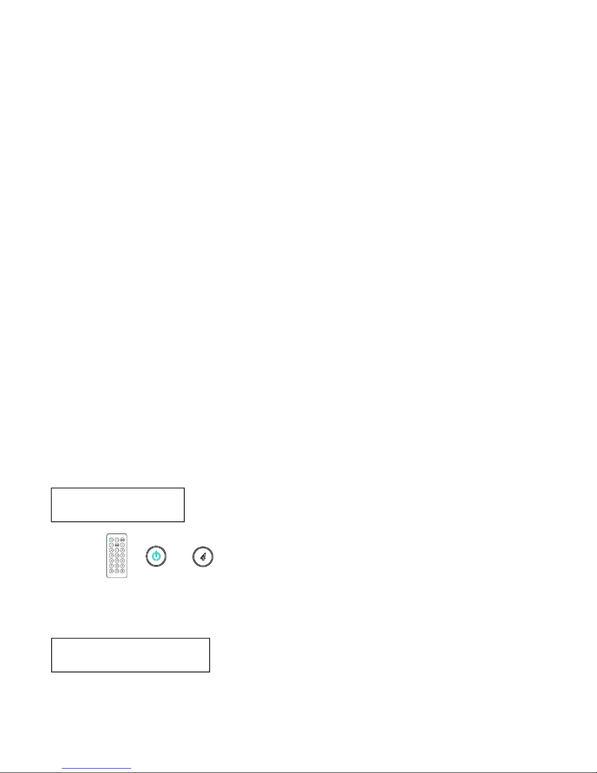
4.5 REMOTE ID:(Default IR ID: 4)
This function permits to match the matrix with the Remote Control IR01. So, a conflict with
other IR remote control is avoided.
After entering MATRIX IR ID menu, press ENTER. The LCM LINE 1 number will flash. Then
Press UP or DOWN button to select the number, and then press ENTER to confirm.
As aftermath, the remote control IR01 must also be set with the same ID
Remote IR ID setting mode: Press and hold the POWER button, then press the
number button which can be set from 0 to 9. (See 5.1)
These settings on IR01 remote control have to be done the first time that you use the IR01
or when you change the batteries. (See 5.0)
4.6 VERSION:
The display shows the matrix firmware version
MATRIX VERSION 1.00
MATRIX IR ID 4
+

11
5.0 Remote Control Function (IR01):
5.1 To command the matrix locally, setup the remote control IR01 ID with the same code
of the Matrix (see 4.5). The default code is 4. (Power+4)
5.2 Warning: These settings have to be done the first time you use the IR01 or when you
change the batteries.
IR ID setup : press and hold POWER button , then press Number key
Remote control button define:
Symbol Function
Power ON/Standby (same as Matrix)
LEFT Left (same as Matrix)
RIGHT Right (same as Matrix)
UP Up (same as Matrix)
DOWN Down (same as Matrix)
ENTER Confirm (same as Matrix)
MENU Menu (same as Matrix)
Quick key1
Quick key2
Quick key3
Quick key4
Quick key5

12
Quick key6
Quick key7
Quick key8
Quick key9
Quick key10
EDID (same as Matrix)
OFF (same as Matrix)
For example: to connect output port 1 to input port 4, press the quick key 1 (OUTPUT 1) and then
press the quick key 4 (INPUT 4).
Warning:
When the matrix is in stand-by mode, the IR Remote Control, can only power-on the matrix.

6.0 REMOTE Control Function:
HS10M supports RS232 and TCP/IP with the protocol as it follows:
6.1 For RS232 CONSOLE:
Connect the RS232 Sub-D 15 pin f. CONSOLE port to the COM port of the host by a Sub-D 15
pin F/M RS232 straight cable (pin 2 to pin 2; pin 3 to pin 3, pin 5 to pin 5)
Communication format is 9600, 8, N, 1 (9600 bps, 8 data bits, no parity check, 1 stop bit)
6.2 For Ethernet TCP/IP (Winsock)
Default IP address: 192.168.0.10, but user must type his own IP address (see 4.3); Port:47011
6.2 Operation Instruction format:
Command + △(Space) + Parameter + Enter
[Command] [Description]
------------------------- -------------------------------------------
POWER△[y] Power on/off
TX[n]△[n] Set RXn to TXn
RX[n]△[m,m,m,m…] Set RXn to multiple TXm,m,m,m...
MATRIX_ID△[p] Set Matrix IR ID
EDID_COPY△[n] Copy EDID from TX n
SAVE △[n] Save setting to #n
LOAD △[n] Load setting from #n
KEY△[y] Panel button& IR remote control Lock/Unlock
DHCP△[y] DHCP client on/off
IP_ADDRESS△[x.x.x.x] Set Matrix IP address
SUBNET_MASK△[x.x.x.x] Set Matrix subnet mask

14
GATEWAY△[x.x.x.x] Set Matrix gateway
MEDIA_TYPE△[z] Network speed select
MAC_FILTER△[y] Mac filter on/off
STATUS Show connection status
VERSION Show firmware version
HELP Help
[Symbol] [Parameter]
------------------------- -------------------------------------------
m 01~10, ff =ALL
n 00 =off, 01~10 =1~10
p 00~09=0~9
x 0~255
y 00 =off, 01 =on
z 00 =auto, 01 =10M, 02 =100M
Example: (△correspond to “space”)
-To route input 4 to output 1, send the following string:
TX01△04Enter
-To route input 2 to all output, send the following string:
RX02△ffEnter
-To route input 2 to output 1,2,4, send the following string:
RX02△01,02,04Enter
-To put in standby the matrix, send the following string:
POWER△00Enter
Commands are case insensitive.
The Matrix will reply OK once the string is correct, NG in case of incorrect string
Warning
To set IP Address, Subnet Mask and Gateway is recommended to use
the front panel buttons menu as described at chapter 4.3

15
7. Web Control Function:
Initial IP Configuration
1. Setup the MATRIX IP Address as your PC domains.(Default 192.168.0.10). Follow the indications at
chapter 4.3
2. Type the IP Address on the URL of your browser to link to the Web UI of the MATRIX host.
3. Web UI Operation :
SWITCH SETTING:
Power : Control MATRIX power on and standby.
Output : Display output 1~10. Output name can be changed by the Aliases page.
Input : Display input 1~10. This field is a drop down menu, that includes Input 1 ~ 10 and
OFF. Input name can be changed by the Aliases page.
Reload : Get updated MATRIX staus and configuration
Advanced : Enter into the “Advanced” page.
Apply : Complete the setting

16
Advanced:
IP address : Change IP address
Subnet mask : Change Subnet mask
Gateway IP : Change Gateway IP
Media Type : Change 10 / 100 / Auto detect
DHCP Client : When setup at Enable, the MATRIX host will automatic IP Address、Subnet
Mask、Gateway. If setup at Disable, the IP Address、Subnet Mask、Gateway must be set from
Advanced page or as described by chapter 4.3.
Auto Reset : The terminal connection permits up to 4 users on line at same time. This
function automatically disconnects the link without data exchange in order to avoid that other
users cannot work. When the Auto Reset time is over, the link is disconnected. (1 ~ 255 Minute
is the time range that can be setup. 0 means no time setup, namely always connected)
Memory : Click to enter Memory setup page
MAC Filter : Click to enter MAC Filter setup page
Aliases : Click to enter Aliases setup page
Device Name : Can change device name
Back : Back to SWITCH SETTING page
Online : Shows the users connected. The maximum is 4 users on line.

17
Aliases:
Aliases page can change input/output name. Enter Apply to finish the setting after change
The new name will updated on the SWITCH SETTING page Output / Input.
Click on Back to jump to Advanced page.
MAC Filter:
MAC Filter can be setup as authorized MAC Address (max 10) to link the MATRIX host
After fill the 10 MAC Address, select Enable and press Apply to complete the setting.
Click on Back to jump to Advanced page.

18
MEMORY:
Save : Save one out of 10 set of channel settings
Load : Reload one out of 10 set of channel settings
Back : Jump to Advanced page.
Specification:
ITEM NO HS10M
HDMI Resolution 4096x2160p 24/25/30Hz 8bit RGB444, 1080p 60Hz 12bit, 3D
Video Input Interface HDMI Type A x 10
Video Output Interface HDMI Type A x 10
RS-232 Input/Output
Interface DB9 f. x 1(CONSOLE)
IR Receive Angle ± 45 degree
IR Receive Distance 5M
Power Adapter DC 12V 6.7A
Power Consumption 5A
Temperature
Operation: 0 to 55℃, Storage: -20 to 85℃, Humidity: up to 95%
Dimension mm 483 x 197 x 88
Weight g 3900
Rev. B

19
8. Android APP Function:
Google Play Download Link
https://play.google.com/store/apps/details?id=sct.com.matrixcontroller
Google Play Download QR code
System Setting
Connect mobile phone to Wi-Fi and set the IP/ subnet mask same of the matrix network segment
Default IP address of 10x10 matrix HS10M-2 is 192.168.0.10
Default IP address of 4x4 matrix HS04M-2 is 192.168.0.200
Default subnet mask is 255.255.0.0
You could also set to DHCP mode, please refer user manual
There are two ways to get the IP address of matrix:
1. Use APP function: Scan Device to get the IP address.
2. Use panel button or IR remote control by press [MENU], select to [ETHERNET] function and press
[ENTER] to enter [IP Address] function than press [ENTER], it will show IP Address in the LCD panel of
matrix

20
Main Page:
When first time enter the APP will see the main page
Bottom left「+」to add matrix
Bottom right「Info」to show information
Scan Device
Touch「+」button at main screen to enter「Scan Device」page
Touch bottom left「Scan Device」to start scan
Touch bottom right pen icon to input the IP address manually
Add Matrix
After scanning it will show all matrixes in the list
Touch the IP in list to enter「Add Device」page
Table of contents
Other ELPRO Matrix Switcher manuals