ELPRO 805U User manual

Contents
Man_805U Rev 1.8 Page 3
Thank you for your selection of the 805U radio modem. We trust it will give
you many years of valuable service.
ATTENTION!
Incorrect termination of supply wires may
cause internal damage and will void warranty.
To ensure your 805U enjoys a long life,
double check ALL your connections with
the user’s manual
before turning the power on.

805U Radio Modem Module User Manual
Page 4©November 2004
How to Use This Manual
To receive the maximum benefit from your 805U product, please read the
Introduction, Installation and Operation chapters of this manual thoroughly
before putting the 805U to work.
Chapter Four Configuration details the configurations available and explains
the diverse operation of the product in detail.
Chapter Five Specifications details the features of the product and lists the
standards to which the product is approved.
Chapter Six Troubleshooting will help if your system has problems and
Chapter Seven specifies the Warranty and Service conditions.
The foldout sheet 805U Installation Guide is an installation drawing
appropriate for most applications.
WARNING
1. In some countries, a radio licence is not required for the 805U telemetry
modules provided the module is installed using the antenna and
equipment configuration prescribed.
2. Where a radio licence is not required, operation is authorised by the
relevant Authority in your country on a non-protection basis. Although
all care is taken in the design of these units, there is no responsibility
taken for sources of external interference. Some delay in the operation
of the module may occur during periods of interference. Systems should
be designed to be tolerant of these delays.
3. To avoid the risk of electrocution, the antenna, antenna cable, and all
terminals of the 805U module should be electrically protected. To
provide maximum surge and lightning protection, the module should be
connected to a suitable earth and the antenna, antenna cable, and the
module should be installed as recommended in the Installation Guide.
4. To avoid accidents during maintenance or adjustment of remotely
controlled equipment, all equipment should be first disconnected from
the 805U module during these adjustments. Equipment should carry
clear markings to indicate remote or automatic operation. eg. "This
equipment is remotely controlled and may start without warning. Isolate
at the switchboard before attempting adjustments."
5. The 805U module is not suitable for use in explosive environments
without additional protection.

Contents
Man_805U Rev 1.8 Page 5
CONTENTS
WARNING ...............................................................................................................................4
CHAPTER ONE INTRODUCTION .........................................................................7
1.1
GENERAL ........................................................................................................................7
1.2 TRANSPARENT MODE......................................................................................................8
1.3 CONTROLLED MODE .......................................................................................................9
1.4 REPEATER UNITS ..........................................................................................................10
CHAPTER TWO INSTALLATION ......................................................................11
2.1 GENERAL ......................................................................................................................11
2.2 ANTENNA INSTALLATION..............................................................................................11
2.2.1 3dB/6dB Collinear antenna..................................................................................12
2.2.2 Yagi antennas.......................................................................................................13
2.3 POWER SUPPLY.............................................................................................................14
2.4 SERIAL CONNECTIONS...................................................................................................14
2.4.1 RS232 Serial Port........................................................................................................14
2.4.2 RS485 Serial Port........................................................................................................15
CHAPTER THREE OPERATION.....................................................................................17
3.1 POWER-UP AND NORMAL OPERATION...........................................................................17
3.2 SERIAL AND RADIO DATA.............................................................................................17
3.2.1 Character Type.....................................................................................................18
3.2.2 Serial Data Rate ...................................................................................................18
3.2.3 Radio Data Rate...................................................................................................19
3.3 ADDRESSING.................................................................................................................19
3.4 TRANSPARENT MODE....................................................................................................20
3.5 TRANSPARENT MODE REPEATERS.................................................................................20
3.6 CONTROLLED MODE .....................................................................................................22
3.6.1 Auto-Connect Controlled Mode .................................................................................24
3.6.2 Low Power Auto-Connect Mode...............................................................................24
3.6.3 Single-Connect Controlled Mode..............................................................................24
3.6.4 Fast Operation Controlled Mode Not used.......................................................25
3.6.5 CTS/RTS Flow Control .............................................................................................25
3.6.6 Intermediate Repeaters................................................................................................25
3.7 WHAT OPERATING MODE TO USE ? ..............................................................................26
3.7.1 Transparent or Controlled Mode?........................................................................26
3.7.2 Error Check ?.......................................................................................................26
3.8 SERIAL / RADIO RATES .................................................................................................27
3.9 OPERATING PROBLEMS .................................................................................................27

805U Radio Modem Module User Manual
Page 6©November 2004
CHAPTER FOUR CONFIGURATION.............................................................................29
4.1 BEFORE CONFIGURING..................................................................................................29
4.2 ADDRESSING.................................................................................................................29
4.3 DEFAULT CONFIGURATION............................................................................................30
4.4 CONFIGURATION PROGRAM ..........................................................................................30
4.4.1 Transparent Mode................................................................................................31
4.4.2 Controlled Mode..................................................................................................32
4.4.3 Other Parameters..................................................................................................34
4.5 HAYES COMMANDS ......................................................................................................37
4.6 CONFIGURATION EXAMPLES .........................................................................................42
4.7 SWITCH CONFIGURATION..............................................................................................44
CHAPTER FIVE SPECIFICATIONS................................................................................46
CHAPTER SIX TROUBLESHOOTING...........................................................................48
6.1 DIAGNOSTICS CHART....................................................................................................48
6.2 TEST FUNCTIONS...........................................................................................................48
6.2.1 Radio Testing - AT&Tx.....................................................................................48
6.2.2 Bit Error Rate Test (BER)....................................................................................50
6.2.3 On-line diagnostics ..............................................................................................50
CHAPTER SEVEN WARRANTY & SERVICE...............................................................51
APPENDIX A HAYES COMMANDS...............................................................................52

Chapter One Introduction
Man_805U Rev 1.8 Page 7
Chapter One INTRODUCTION
1.1 General
The 805U radio modem module has been designed to provide flexible and reliable radio
modem functions, at an economical price. Radio modems transmit serial data over a long
distance via radio. The serial data is not changed - the output data is the same as the input
data. Although the 805U is intended to be simple in its application, it also provides many
sophisticated features. This manual should be read carefully to ensure that the modules are
configured and installed to give reliable performance.
Each 805U module will connect to a host device by RS232 or RS485 serial connection.
Examples of host devices are PLC’s, data loggers, intelligent transducers and computers.
The 805U unit can receive data from the host device and transmit this data by radio to another
(or several) 805U module. The other module will recreate the serial data and output it as
either a RS232 or RS485 serial signal. The 805U unit provides two-way communications -
each module can accept serial data and also output serial data.
The 805U module includes power supply, microprocessor controller, serial input/output
circuits and a 900MHz frequency-hopping spread-spectrum radio transceiver - no external
electronics are required. The 805U radio frequency has been selected to meet the
requirements of unlicensed operation for remote monitoring and control of equipment. That
is, a radio licence is not required for the 805U modules in many countries. See Chapter Five
Specifications for details. The units are configured from a PC using a “free-ware”
configuration package, or from a PC terminal using Hayes commands.
RS232 is an electrical standard format for a full
duplex point-to-point serial connection. RS485
is an electrical standard format for a half-duplex
multidrop serial connection. Up to 32 devices
can communicate on a common RS485 serial
bus. Each 805U unit can only connect to one
serial signal - either RS232 or RS485.
However different modules in the same system
can connect to different types of serial signals. For example, RS232 data from one host
device can be transmitted to a remote 805U unit and output as RS485 data to another host
device.
The 805U has been designed to be flexible enough to cover a wide range of applications. The
user is able to configure many different parameters such that the 805U unit will connect
reliably to different types of host devices. Before the radio modem can be used, these
parameters must be configured. Some of these parameters are :-
•Character type - the 805U will accept a variety of 7 or 8 data bit characters
•Serial Data Rate - between 1200 and 115200 bits/sec
•Radio Data Rate - 19200, 38400 or 76800 bits/sec
•Operating mode - transparent mode or controlled mode .
HOST
805U
RS232
HOST
805U
RS485

805U Radio Modem Module User Manual
Page 8©November 2004
The operation of the 805U radio modem is relatively simple. As data is received at the serial
port, the data is transmitted on the radio channel. Up to 530 bytes of data can be transmitted
in one transmission. The radio transmission commences when the first data byte is received,
and ends when there are no more data bytes in the input buffer, or when the number of bytes
transmitted equals the maximum message length (user configurable - default 530 bytes). If
more than 530 bytes is input, the 805U unit will transmit the first 530 bytes, then the next
530 bytes, and so on until all of the data has been transmitted.
Because the radio data rate could be less than the input serial data rate, an input memory
buffer of 2Kbytes is provided. The RS232 connection provides CTS control to prevent the
buffer overflowing. There are no data flow control signals for RS485.
A radio channel cannot provide as secure a data channel as a wired connection. The 805U
uses a radio band with a low level of natural or industrial noise, however there is a chance of
interference from other users of the unlicensed radio channel. We recommend that the flow
of data over the radio channel is controlled by using error detection and “handshaking” - that
is, returning an acknowledgment transmission if a data packet is received on the radio channel
without error. This function can be performed by either the host devices or the 805U
modules. The modules may be configured by the user to operate in one of two modes. In
transparent mode, it is assumed that the host devices control the flow of data. In controlled
mode, the 805U units control the flow of data.
1.2 Transparent Mode
The default configuration of the 805U
modem is transparent mode - the modules
are set in this mode at the factory. In
transparent mode, the 805U provides no
control of the data transmissions (no error
correction). Input data is simply transmitted
by radio and every other 805U unit in that
system which receives the transmission will
output the data. This mode relies on the
host devices to perform the “handshaking”
function, and re-transmitting serial data if
the data is corrupted (no “handshake”). It also relies on the host devices to include any
addressing necessary in the data. In this mode, modules are not configured with a unit
address. Data is “broadcast” - every other 805U in the system will receive the data and
output the data to their individual host devices. The user may configure the 805U modems to
add error checking to each data packet transmitted - if error checking is configured, data
will not be output if it is received without a correct error-check. This feature provides
additional protection against corruption of the data during the radio transmission. If error-
checking is not configured, then the data received by radio will be output without checking
for errors.
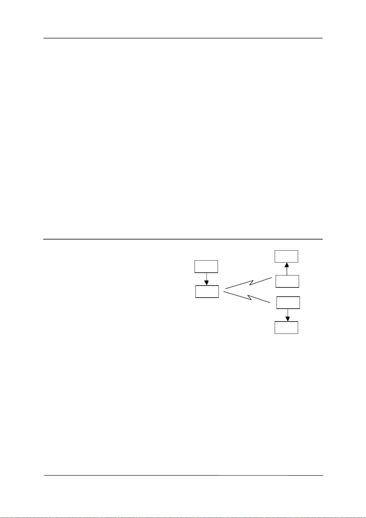
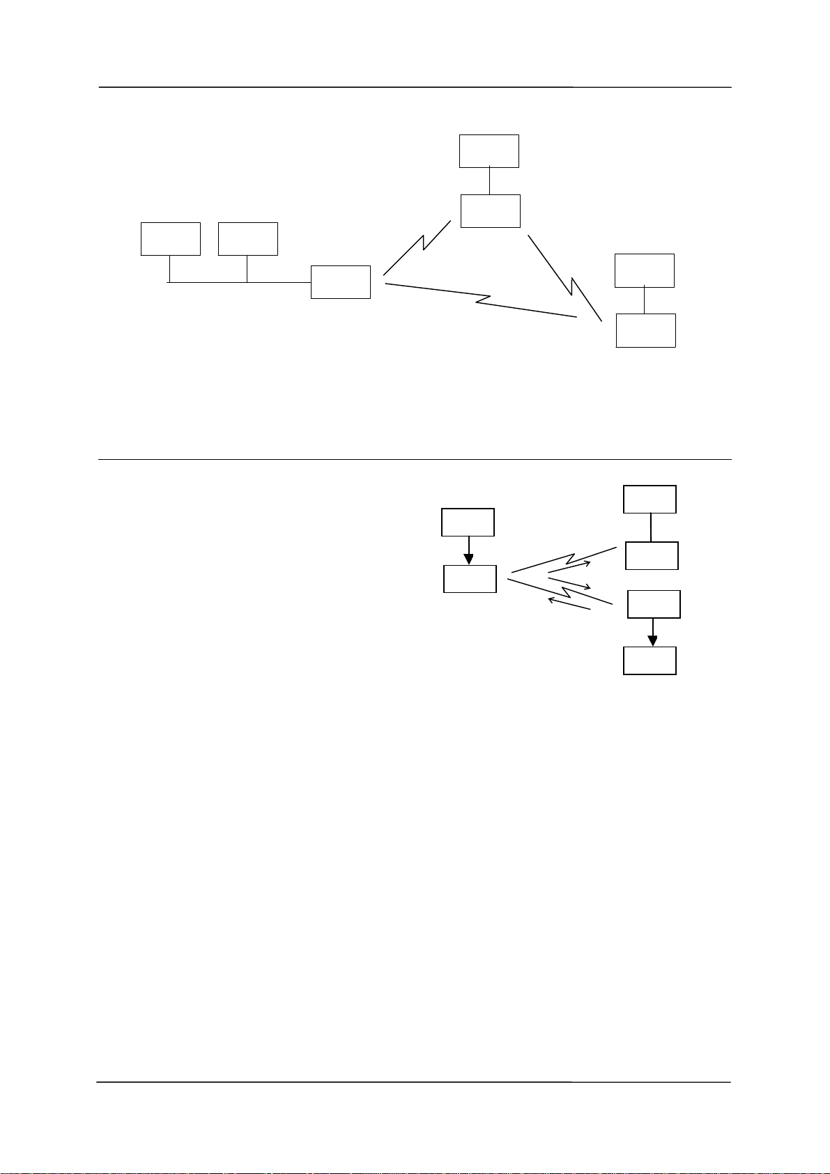
Transparent mode is “point-to-multipoint” communications, suitable for a host device which
is able to communicate on a multi-drop “bus” type network. An example of an application is
the use of radio modems to extend a PLC RS485 network. The serial messages from the
PLC’s already include PLC addressing and error detection/correction to control the flow of
data
HOST
805U
DATA
HOST
805U
DATA
HOST
805U
DATA

Chapter One Introduction
Man_805U Rev 1.8 Page 9
.
1.3 Controlled Mode
“Controlled mode” provides “point-to-
point” communications similar to telephone
modems. In controlled mode, the flow of
data is controlled by the 805U units. Each
805U unit is configured with an address by
the user, and a destination address for the
data to be transmitted to. Data is
transmitted addressed to the destination
module, and only this module will output
the serial data. The source module will add
an error-check (16 bit CRC) to the data
transmitted by radio. The destination module will process the error-check, and if correct, it
will transmit an acknowledgment message (ACK) back to the source module. If the source
module does not receive a ACK, it will re-transmit the data. The source module will attempt
to transmit the data up to five times, until an acknowledgment (ACK) is received. If an
acknowledgment is still not received, then the DCD signal on the RS232 port will be reset
and a alarm message can be sent to the host via the serial port.
An example of an application using controlled mode would be a radio modem link between
an intelligent gas analyser and a monitoring computer system. Intelligent transducers do not
normally provide addressing or error checking functions - these would be provided by the
805U modules.
In controlled mode, the destination address may be pre-set, or set on-line by the host device
using “Hayes” commands. Hayes commands are a standard set of commands used with
conventional telephone modems. An example of an application that would use Hayes
command to set destination addresses would be a central computer polling data loggers for
periodic information.
PLC
805U
805U
RS485
PLC
PLC
805U
PLC
HOST
805U
DATA
HOST
805U
NO DATA
HOST
805U
DATA
#1 #2
#3

805U Radio Modem Module User Manual
Page 10 © November 2004
1.4 Repeater Units
A 805U unit may be used as a repeater to re-transmit radio messages. The purpose of a
repeater unit is to extend radio range.
In transparent mode, there can be an unlimited number of repeaters, however with some
conditions (refer to Section 3.5).
The repeater in transparent mode will repeat every transmission it receives.
In controlled mode, up to five repeaters may be configured for any transmission path. The
repeaters are configured by address.
PLC
805U
805U
RS485
PLC
PLC
805U
PLC
REPEATER
805U 805U 805U 805U
805U 805U 805U 805U

Chapter Three Operation
Man_805U Rev 1.8 Page 11
Chapter Two INSTALLATION
2.1 General
The 805U module is housed in an rugged aluminium case, suitable for DIN-rail mounting.
Terminals will accept wires up to 2.5 sqmm in size.
Normal 110-240V mains supply should not be connected to any terminal of the 805U
module. Refer to Section 2.3 Power Supply.
Before installing a new system, it is preferable to bench test the complete system.
Configuration problems are easier to recognize when the system units are adjacent.
Following installation, the most common problem is poor communications caused by
incorrectly installed antennas, or radio interference on the same channel, or the radio path
being inadequate. If the radio path is a problem (ie path too long, or obstructions in the way),
then higher performance antennas or a higher mounting point for the antenna may rectify the
problem. Alternately, use an intermediate 805U Module as a repeater.
The foldout sheet 805U Installation Guide provides an installation drawing appropriate to
most applications. Further information is detailed below.
Each 805U module should be effectively earthed via the "GND" terminal on the 805U
module - this is to ensure that the surge protection circuits inside the 805U module are
effective.
2.2 Antenna Installation
The 805U module will operate reliably over large distances. The distance which may be
reliably achieved will vary with each application - depending on the type and location of
antennas, the degree of radio interference, and obstructions (such as hills or trees) to the radio
path. The expected range for radio data rates of 19200 bits/sec is 5 km line-of-sight . At
38400 bit/sec, the expected distance will be approx 3 km, and at 76800, the distance will be
1.5 km.
Where it is not possible to achieve reliable communications between two 805U modules, then
a third 805U module may be used to receive the message and re-transmit it. This module is
referred to as a repeater.
An antenna must be connected to each 805U module using the female SMA connector at the
top of the module.
To achieve the maximum transmission distance, the antennas should be raised above
intermediate obstructions such that the radio path is true “line of sight”. Because of the
curvature of the earth, the antennas will need to be elevated at least 5 metres above ground
for paths of 5 km. For short distances, the modules will operate reliably with some
obstruction of the radio path. Obstructions which are close to either antenna will have more
of a blocking effect than obstructions in the middle of the radio path. For example, a group
of trees around the antenna is a large obstruction, and the antenna should be raised above the
trees. However if there is at least 100 metres of clear path before a group of trees, the trees
will have less affect on the radio path.

805U Radio Modem Module User Manual
Page 12 © November 2004
The modules provide test diagnostics to test the radio path and display radio signal strength.
An antenna should be connected to the module via 50 ohm coaxial cable (eg RG58, Cellfoil
or RG213) terminated with a male SMA connector. The higher the antenna is mounted, the
greater the transmission range will be, however as the length of coaxial cable increases so do
cable losses. For use on unlicensed frequency channels, there are several types of antennas
suitable for use. It is important antennas are chosen carefully to avoid contravening the
maximum power limit on the unlicensed channel - if in doubt refer to an authorized service
provider.
The maximum net gain of the antenna/cable configuration permitted is 0dB.
The gains and losses of typical antennas are
Antenna Gain (dB)
3dB Collinear 3
6dB Collinear 6
6 element Yagi 10
9 element Yagi 12
16 element Yagi 15
Cable type Loss (dB per 10 m)
RG58 -5
RG213 -2.5
Cellfoil -3
The net gain of the antenna/cable configuration is determined by adding the antenna gain and
the cable loss. For example, a 6 element Yagi with 20 metres of RG58 has a net gain of 0 dB
(10dB – 10dB).
Connections between the antenna and coaxial cable should be carefully taped to prevent
ingress of moisture. Moisture ingress in the coaxial cable is a common cause for problems
with radio systems, as it greatly increases the radio losses. We recommend that the
connection be taped with a layer of PVC insulating tape, then a layer of vulcanizing tape
such as “3M 23 tape”, with a final layer of PVC insulating tape.
Where antennas are mounted on elevated masts, the masts should be effectively earthed to
avoid lightning surges. Although the 805U module is fitted with surge protection, additional
surge suppression devices are recommended if lightning surge problems are experienced. If
the antenna is not already shielded from lightning strike by an adjacent earthed structure, a
lightning rod may be installed above the antenna to provide shielding.
2.2.1 3dB/6dB Collinear antenna.
A collinear antenna transmits the same amount of radio power in all directions - as such that
are easy to install and use. For marginal radio paths, the following lengths are the
recommended maximum for the coaxial cable to the antenna. RG58 -10 metres RG213 -
20 metres. Note that this applies to marginal paths only - if the radio path has a strong radio
signal, then longer lengths of cable ( and hence more cable loss) can be tolerated. If more
than 20 metres of cable is required for a marginal path installation, then a low loss cable such

Chapter Three Operation
Man_805U Rev 1.8 Page 13
as 10D-FB, or a higher gain antenna should be used. Collinear antennas should be mounted
vertically, at least 1 metre away from a wall or mast.
2.2.2 Yagi antennas.
A Yagi antenna provides high
gain in the forward direction,
but lower gain in other
directions. This may be used
to compensate for coaxial cable
loss for installations with
marginal radio path.
The Yagi gain also acts on the
receiver, so adding Yagi
antennas at both ends of a link
provides a double improvement.
Yagi antennas are directional.
That is, they have positive gain
to the front of the antenna, but
negative gain in other
directions. Hence Yagi
antennas should be installed
with the central beam horizontal
and must be pointed exactly in
805U
Antenna installed
with drain holes
down
Coax feed looped
at connection
90o
1m minimum
COLINEAR
ANTENNA
MAST
EARTH STAKE
IF GROUND CONDITIONS ARE
POOR, INSTALL MORE THAN
ONE STAKE
INSTALL AERIAL ABOVE
LOCAL OBSTRUCTIONS
ANT
805U
SURGE
ARRESTOR
(OPTIONAL) COAXIAL CABLE
WEATHERPROOF
CONNECTORS WITH
“3M 23” TAPE
STRESS RELIEF LOOP
PROVIDE GOOD
GROUND
CONNECTION TO
MAST, MODULE
AND SURGE
ARRESTOR
GND

805U Radio Modem Module User Manual
Page 14 © November 2004
the direction of transmission to benefit from the gain of the antenna. The Yagi antennas may
be installed with the elements in a vertical plane (vertically polarized) or in a horizontal
plane (horizontally polarized). For a two station installation, with both modules using Yagi
antennas, horizontal polarization is recommended. If there are more than two stations
transmitting to a common station, then the Yagi antennas should have vertical polarization,
and the common (or “central” station should have a collinear (non-directional) antenna.
Also note that Yagi antennas normally have a drain hole on the folded element - the drain
hole should be located on the bottom of the installed antenna.
2.3 Power Supply
The 805U module is powered by a 10 - 30VDC or 13 – 24VAC supply, minmum 9 Watt
capacity.
For DC supplies, the negative side of the
supply is connected to "COM" and may be
connected to “ground”. The supply negative is
connected to the “GND” terminal internally.
The positive side of the supply must not be
connected to earth. The DC supply may be a
floating supply or negatively grounded.
The power requirements of the 805U units is
80mA at 12VDC or 50mA at 24VDC. The
power requirements in low power mode is
20mA at 12VDC.
2.4 Serial Connections
2.4.1 RS232 Serial Port
The serial port is a 9 pin DB9 female and provides for connection to a host device as well as a
PC terminal for configuration, field testing and for factory testing. This port is internally
shared with the RS485 - ensure that the RS485 is disconnected before attempting to use the
RS232 port. Communication is via standard RS232 signals. The 805U is configured as DCE
equipment with the pinout detailed below.
Hardware handshaking using the CTS/RTS lines is provided. The CTS/RTS lines may be
used to reflect the status of the local unit’s input buffer, or may be configured to reflect the
status of CTS/RTS lines at the remote site. The 805U does not support XON/XOFF.
Example cable drawings for connection to a DTE host (a PC) or another DCE host (or modem)
are detailed below.
805U
10 – 30 +
VDC -
+
-
805U
13 - 24
VAC
+
-

Chapter Three Operation
Man_805U Rev 1.8 Page 15
DB9 Connector Pinout
Pin Name Direction Function
1DCDOut Data carrier detect –
- driven when link is established in controlled mode
- driven always in transparent mode
2RD Out Transmit Data – Serial Data Output
3TD In Receive Data – Serial Data Input
4DTRIn Data Terminal Ready - DTR can be configured to initiate low power
mode, or to force a link disconnection (“hang up” in controlled mode.
5SG Signal Ground
6DSROut Data Set Ready - always high when unit is powered on.
7RTSIn Request to Send - hardware flow control configurable
8CTSOut Clear to send - hardware flow control configurable
9RI Ring indicator - indicates another module is attempting to connect in
controlled mode.
805U
DB9
MALE
DTE HOST
DB9
FEMALE
805U
DB9
MALE
DCE HOST
DB9
MALE
2.4.2 RS485 Serial Port
The RS485 port provides for communication between the 805U unit and its host device using a
multi-drop cable. Up to 32 devices may be connected in each multi-drop network. Note that
the RS485 port is shared internally with the RS232 port - make sure that the RS232 port is
disconnected before using the RS485 port.
As the RS485 communication medium is shared, only one of the units on the RS485 cable
may send data at any one time. Thus communication protocols based on the RS-485
standard require some type of arbitration.
RS485 is a balanced, differential standard but it is recommended that shielded, twisted pair
cable be used to interconnect modules to reduce potential RFI. It is important to maintain the
polarity of the two RS485 wires. An RS485 network should be wired as indicated in the
diagram below and terminated at each end of the network with a 120 ohm resistor. On-board
120 ohm resistors are provided and may be engaged by operating the single DIP switch in the
end plate next to the RS485 terminals. The DIP switch should be in the “1” or “on” position
to connect the resistor. If the module is not at one end of the RS485 cable, the switch should
be off.

805U Radio Modem Module User Manual
Page 16 © November 2004
HOST 805U HOST
RS485 CONNECTIONS
120Ω
RS485
SUPPLY
RS232
DIP SWITCH
FOR 120Ω
120
HOST HOST
805U
+
-
+
-
+
-
RS485 CONNECTION USING TERMINATING RESISTOR

Chapter Three Operation
Man_805U Rev 1.8 Page 17
Chapter Three OPERATION
3.1 Power-up and Normal Operation
When power is initially connected to the 805U module, the module will perform internal
diagnostics to check its functions. The following table details the status of the indicating
LEDs on the front panel under normal operating conditions.
LED Indicator Condition Meaning
OK On Normal Operation
Radio RX GREEN flash
RED flash
Radio receiving data
Weak radio signal
Radio TX Flash Radio Transmitting
Serial RX GREEN flash
RED flash
Serial Port Receiving
CTS low
Serial TX GREEN flash Serial Port Transmitting
DCD On Transparent mode - always on
Controlled mode - on when
communications link is established
DCD Off Communications failure or link not
established
Other conditions indicating a fault are described in Chapter Six Troubleshooting.
3.2 Serial and Radio Data
The 805U module provides a full-duplex RS232 serial port and half-duplex RS485 serial port
- only one serial port can be used at any one time. The radio communications is half-duplex
- this means that the 805U operates at half duplex. Many applications use full duplex RS232
communications but do not require full duplex - the protocol used operates at half-duplex
and will operate with the 805U without problems. If an application really requires full duplex
communications, then the 805U should not be used.
Data input at the serial port is placed into the input buffer. This buffer will store 2Kbytes of
data, and CTS/RTS control can be configured on the RS232 port to prevent overflow.

805U Radio Modem Module User Manual
Page 18 © November 2004
When the 805U unit detects data in the input buffer, it initiates a radio message. The radio
message will end when the number of transmitted bytes reaches the maximum message length
(configurable by the user), or if the input buffer becomes empty.
If the configured serial data rate is the same or more than the radio data rate, then data is
transmitted as soon as it enters the input buffer - data “streams” from the input buffer to the
radio port. If the serial rate is less than the radio rate, then the transmission will be delayed
for a period to allow sufficient data to build up in the input buffer to avoid the radio emptying
the input buffer before a complete serial message has been input. The 805U will calculate the
amount of delay depending on the difference between the serial and radio rates.
The radio transmission will stop when the input buffer is empty or when the radio has
transmitted the maximum number of bytes (user configurable - maximum 530 bytes). If
there is still data in the input buffer, the 805U will start another radio transmission.
If error checking is configured, then a 16 bit CRC error-check is added to the end of the
transmitted data packet. The receiving module will receive the full data packet and check the
CRC before outputting the data.
The maximum size of the data packet is configurable by the user (maximum is 530 bytes). If
less data than the maximum size is input to the 805U, then the 805U will transmit the actual
data input. If more data is input than the maximum size, then the 805U will transmit
multiple packets until all of the data is transmitted.
Because of radio start-up delays, the effective radio data rate will be lower than the
transmitted data rate. If you are sending large blocks of data, and the serial rate is equal or
more than the radio rate, we recommend that you use CTS/RTS flow control to prevent the
input buffer from overflowing.
3.2.1 Character Type
The 805U may be configured by the user to recognize the following types of characters - 7
or 8 data bits, even or odd or no parity, 1 or 2 stop bits.
Most applications will require the character type to be the same at each 805U modem in the
system. Nevertheless, the character type may be configured to be different at different 805U
modems. Data is transmitted by radio as an eight-bit byte without stop or start bits. If the
input data is 7 data bits, then the byte transmitted by radio comprises the 7 bits plus a zero
bit. Input characters with 8 bits are transmitted as just the 8 data bits, with no parity.
Because the data is transmitted without parity, the user may configure CRC error checking to
be added to each transmitted data packet. Data is output at the destination module based on
the character type configured at that module - that is, the start/stop bits and parity is added to
the radio data.
3.2.2 Serial Data Rate
The communications baud rates supported on both the RS232 serial port and the RS485 serial
port are 1200, 2400, 4800, 9600, 14400, 19200, 28800, 31250, 38400, 57600, 76800 and
115200 baud - the user selects one of these rates during the configuration of the modem.

Chapter Three Operation
Man_805U Rev 1.8 Page 19
3.2.3 Radio Data Rate
The data is transmitted by radio as direct modulated synchronous data at 19200, 38400 or
76800 bits/second. The user must configure the radio data rate at each 805U module. The
configured radio data rates must be the same for each module in a system.
At 19200 and 38400 bits/sec, the 805U adds forward error correction in the transmitted data.
This is added automatically and is different to the configurable CRC error-check.. The radio
range at 19200 baud is better than 38400 or 76800. The expected range at 38400 is 60% of
maximum and at 76800 is 30%.
The radio message includes the following :-
•A 5 - 10 msec leading sequence of alternating 1’s and 0’s provides the receiving unit
with time to capture and lock onto the incoming signal.
•A system address is superimposed on each message to provide discrimination between
different 805U systems on the same radio channel. Each 805U unit in the same system must
be configured with the same system address - refer Section 4, Configuration. Although
other 805U modules may hear the radio transmissions, because they have a different system
address, the radio transmission is ignored and no serial data is output.
•In transparent mode, a group address is included, and in controlled mode, unit
addressing is included.
An error-check (16 bit CRC) may be configured by the user.
Up to 530 bytes of data may be transmitted in a message - the maximum message size is
configurable between 10 and 530 bytes. The data consists of a sequence of 8 bit bytes. Start,
stop and parity bits are not transmitted, but they are re-generated at the receiving unit (if
configured).
A “transmit delay” time and a “receive delay” time may also be configured. These parameters
may be used to fine tune and give priority to different 805U units in a system.
•After each message is transmitted, a 805U unit will not transmit another message during the
transmit delay time. This could be used to allow a reply message to be received before the
next message is sent.
•After a message is received, a message will not be transmitted during the receive delay
time. This could be used to delay a reply message until other messages have been sent.
3.3 Addressing
A 805U network comprises modules with the same "system" address. Only modules with the
same system address will communicate with each other. This feature allows more than one
system to operate in the same area on the same radio channel. We recommend that you select
a random number for the system address.
In transparent mode, each module is also configured with a “group” address. A system may
comprise several groups or sub-systems. Only modules with the same system and group
address will communicate directly with each other - but modules with different group

805U Radio Modem Module User Manual
Page 20 © November 2004
addresses can communicate via a repeater. The group address is used for repeater operation in
transparent mode. The group address is not used in controlled mode.
A 805U can also be configured with a “unit” address - this gives the module a unique
identification. The unit address feature is not used in transparent mode, but it is used in
controlled mode.
3.4 Transparent Mode
In transparent mode, radio messages are transmitted without unit addressing. Units do not
provide handshaking functions to control the flow of data. Every unit which receives the
radio message, and has the correct system and group addresses, will output the data.
Transparent mode operation is effectively a broadcast system.
Data received at the serial port is transmitted out of the radio port. Data received from the
radio is transmitted out of the serial port. Prior to transmitting, units will listen to the radio
channel to ensure that it is clear - units will hold off from transmitting until the radio
channel is clear. At the RS232 port, the CTS pin can be configured to go high while there is
space in the input data buffer - otherwise it is always high.
Host devices should provide a suitable protocol to ensure that error checking, handshaking
and implementation of an appropriate re-transmission scheme is provided. This mode of
operation is particularly suited to devices designed to operate over a multidrop network, such
as PLC systems designed for operation over a RS-485 network.
The time taken to transmit a message is :-
lead-in system/group addr data error check (if configured)
|---------------|-----------------|------------------------------------------|--------------|
5 msec 2 bytes 0.5ms per byte 2 bytes
1 ms @19.2Kb @ 19.2Kb 1ms @ 19.2Kb
If error checking is not configured at the receiving unit, data will start to be output
approximately 1 msec after the system address has been received. If error checking is
configured, data will be output approx 2msec after the end of the message. For example, a
message with 20 bytes of data transmitted at 19200 bits/sec will begin to be output approx
12msec after the data is input, if there is no error checking, or 24msec after the data is input
if error checking is configured.
3.5 Transparent Mode Repeaters
A module can be configured as a transparent mode repeater. In this mode, the module will
operate as a normal transparent mode module, plus it will also re-transmit any radio messages
that it receives. However it will change the group address in the re-transmitted message. The
transparent mode repeater is configured with two group addresses. When it receives a radio
message with one of these group addresses, it will re-transmit the message using the other
group address (assuming that the system address is correct).
One of the group addresses will be its normal or “first” group address. If a transparent mode
repeater receives a message on its first group address, it will output the data on its serial port,
and will also re-transmit the message using its second group address. That is, the re-

Chapter Three Operation
Man_805U Rev 1.8 Page 21
transmitted message will now have the second group address. Only 805U modules
configured with the second group address will accept the re-transmitted message.
If a transparent mode repeater receives a message on its second group address, it will re-
transmit the message on its first group address, but it will not output the data on its serial
port.
Here is an example :
Module A, B and C are
configured as transparent
repeaters. Module A is
configured with group
addresses 1 & 2, module
B with group addresses 2
& 3 and module C with
group addresses 3 & 4.
Module S and T are
configured with group
address 1 (only one group
address as it is not configured as a repeater). When S transmits a message, T and A will
receive it and output the data. If module X can hear the message, it will not output it as
module X is configured with group address 2.
Repeater A will re-transmit the radio message, but on group address 2. Module S and T will
receive the re-transmitted message, but will not output the message as the group address is
now wrong. Module X will receive the message and will output the message as the group
address is now correct.
Repeater B will also receive the re-transmitted message from A, and will output the data as
well as re-transmit on group address 3. The only other module which is also on group
address 3 is repeater C. It will accept the message and re-transmit it on group address 4 - to
module Z. Note that when a message is transmitted from a remote module, the repeaters will
only transmit a message in one direction. For example :
When X
transmits a
message,
repeater A will
receive the
message on
group address
2. Repeater A
will not output
the data as the
group address
is not the
repeater’s first
group address.
Repeater A will re-transmit on group address 1 to modules S and T. But repeater B will not
accept the re-transmitted message on group address 1.
ABC
Group Address
First 1 2 3
Second 2 3 4
S
TXZ
Repeaters
Remote
Modules
Group Address 1 2 4
ABC
Group Address
First 1 2 3
Second 2 3 4
S
TXZ
Repeaters
Remote
Modules
Group Address 1 2 4
Table of contents
Other ELPRO Modem manuals