WG AQS/TH-UP sensor 1
WG AQS/TH-UP sensor • Version: 19.12.2018 • Technical changes and errors excepted. • Elsner Elektronik GmbH • Sohlengrund 16 • 75395 Ostelsheim • Germany • www.elsner-elektronik.de • Technical Service: +49 (0) 7033 / 30945-250
EN
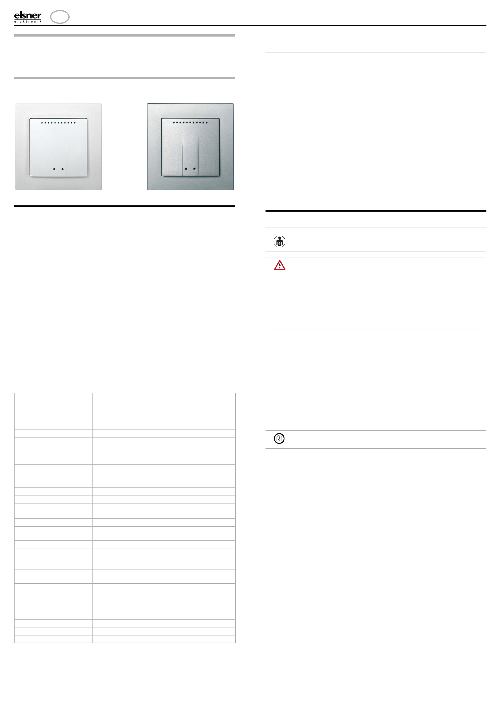
WG AQS/TH-UP
Indoor Sensor
Technical specifications and installation instructions
Item numbers 20553 (white), 20554 (aluminium coloured)
1. Description
The WG AQS/TH-UP sensor transmits via radio the temperature, humidity and
CO2 content of the air to the WS1 Colour/Style or (KNX) WS1000 Colour/ Style con-
troller. Several sensors can be "taught" on one controller. The teaching procedure is
described in the chapter "Learning wireless connections" (Controller manual).
The WG AQS/TH-UP consists of the housing, the sensor printed circuit board/base-
plate, the CO2 sensor and a frame. As an alternative to the frame provided, a frame
in the switch series used in the building can be used. You also need a junction box
(Ø 60 mm, 42 mm deep, not included in the deliverables).
For the power supply (11...30 V DC) e.g. 12 V DC can be drawn from the connector
board for the control system (multifunction-input).
Suitable for:
• WS1 Color, WS1 Style (from software version 1.819)
• WS1000 Color, WS1000 Style (from software version 1.819)
• KNX WS1000 Color, KNX WS1000 Style (from software version 1.819)
1.0.1. Deliverables
• Housing
• Baseplate (circuit board)
•CO
2-Sensor unit
•Frame
You also need (not included in deliverables):
• Junction box Ø 60 mm, 42 mm depth
1.1. Technical specifications
The product is compliant with the provisions of the following EC guidelines.
1.1.1. Measurement accuracy
Deviations in measured values due to interfering sources (see chapter installation
site) must be corrected in the controller menu in order to achieve the specified sen-
sor accuracy.
The specified CO2 measurement accuracy is achieved after a run-in of 24 hours
(without voltage interruption), if the sensor comes into contact with fresh air
(350…450 ppm) at least once during this period. During the warm-up phase the rea-
ding may not be displayed at all or wrongly, or remain frozen at 2001.
After this, the CO2-sensor performs a self-calibration every two weeks, in which the
lowest CO2value measured during this period (without voltage interruption) is taken
as a reference for fresh air.
In order to ensure permanent accuracy, the sensor should be supplied with fresh air
at least once every two weeks. This is normally the case during room ventilation.
The measured temperature and humidity values can be corrected in the cont-
roller menu. This may be necessary if the values at the sensor do not correspond to
the room average (for example, if the sensor is positioned in a location which is war-
mer than average). Please be aware that usable measured values can only be achie-
ved approx. two hours after putting the sensor into operation (warm-up phase).
Radio connections > Status (In the controller manual)
System > Installation > Radio connection > Status > [Device]
2. Installing the indoor sensor
2.1. Installation notes
Installation, testing, operational start-up and troubleshooting should
only be performed by an electrician.
CAUTION!
Live voltage!
There are unprotected live components inside the device.
• National legal regulations are to be followed.
• Ensure that all lines to be assembled are free of voltage and take
precautions against accidental switching on.
• Do not use the device if it is damaged.
• Take the device or system out of service and secure it against
unintentional use, if it can be assumed, that risk-free operation is no
longer guaranteed.
The device is only to be used for its intended purpose. Any improper modification
or failure to follow the operating instructions voids any and all warranty and gua-
rantee claims.
After unpacking the device, check it immediately for possible mechanical damage.
If it has been damaged in transport, inform the supplier immediately.
The device may only be used as a fixed-site installation; that means only when as-
sembled and after conclusion of all installation and operational start-up tasks and
only in the surroundings designated for it.
Elsner Elektronik is not liable for any changes in norms and standards which may
occur after publication of these operating instructions.
2.1.1. Installation location
Install and use only in dry interior rooms.
Avoid condensation.
When selecting an installation location, please ensure that the measurement results
are affected as little as possible by external influences. Possible sources of interfe-
rence include:
• Direct sunlight
• Draughts from windows and doors
• Draughts from ducts which lead from other rooms, or the outside to the
junction box in which the sensor is mounted
• Warming or cooling of the building structure on which the sensor is mounted,
e.g. due to sunlight, heating or cold water pipes
• Connection lines and empty ducts which lead from warmer or colder areas to
the sensor
Temperature deviations caused by such sources of interference must be corrected
in the control system menu, in order to achieve the specified sensor accuracy (see
manual chapter Wireless connections > Status).
For a correct CO2measurement it is necessary to install the device in a windproof
junction box.
Housing Plastic (partially painted)
Colours • White, glossy (similar to RAL 9016 Traffic White)
• Matt aluminium
Assembly Flush mounting (Flush mounting in junction box Ø 60
mm, 42 mm depth)
Protection category IP 20
Dimensions Housing approx. 55 x 55 (W x H, mm), construction
depth
approx. 15 mm baseplate approx. 71 x 71 (W x H,
mm)
Total weight approx. 50 g
Ambient temperature Operation -20…+70°C, storage -30…+70°C
Ambient humidity max. 95% RH, avoid condensation
Operating voltage 11…30 V DC
Power max. 35 mA
Data output Via wireless
Wireless frequency 868.2 MHz
Protocol own protocol (Elsner RF)
Temperature measurement
range
-20…+70°C
Resolution (temperature) 0.1°C
Accuracy (temperature) ±0,6°C at -20...-10°C
±0,5°C at -10...+65°C
±0,6°C at +65...+70°C
Humidity measurement
range
0…95% RH
Humidity resolution 0.1%
Humidity accuracy ±7,5% RH at 0...10% RH
±4,5% RH at 10...90% RH
±7,5% RH at 90…95% RH
Humidity drift ± 0.5% RH per year in normal atmosphere
CO2 measurement range 0...2000 ppm
CO2 resolution 1 ppm
CO2 accuracy ±50 ppm ±3% of the measured value


