manuals.online logo
Brands
  1. Home
  2. •
  3. Brands
  4. •
  5. elsner elektronik
  6. •
  7. Control Unit
  8. •
  9. elsner elektronik IMSG-UC-4H User manual

elsner elektronik IMSG-UC-4H User manual

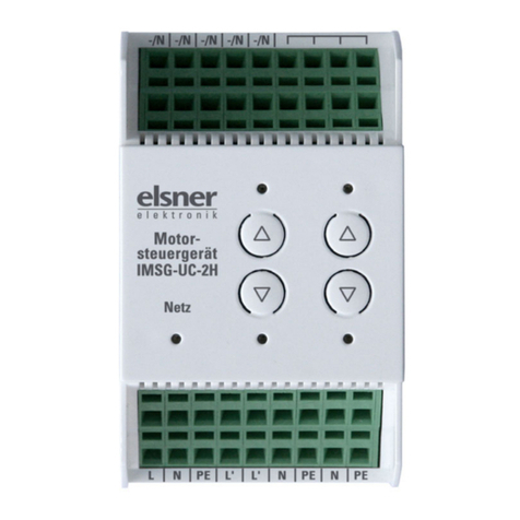
Motor control unit IMSG-UC-4H 1
Motor control unit IMSG-UC-4H • Version: 28.05.2020 • Technical changes and errors excepted. • Elsner Elektronik GmbH • Sohlengrund 16 • 75395 Ostelsheim • Germany • www.elsner-elektronik.de • Technical Service: +49 (0) 7033 / 30945-250
IMSG-UC-4H
Motor control unit
1. Description
The Motor control unit IMSG-UC-4H allows four 230V drives to be controlled.
The unit offers the possibility of operating the connected motors via integrated
buttons or manually via up/down hand switches.
Functions:
•Forfour 230V drives (Up/Down)
•Withkey pad (manual operation) and status LEDs
•4 hand switch connections (extension inputs) for unlocked double
button (manual operation on the spot, can be set to Standard or Comfort
mode)
•Central and extension inputs with variable voltage (12…80 V DC,
12…240 V AC)
• Setting the central control unit to "Deadman" or "Latch"
• The central command (continuous voltage) has priority over a movement
command from the extension inputs
•Storing one movement position per drive
• Pause to reverse direction 1 second, motor runtime 240 seconds
• Connect through clamps
• Potential-free relays
1.1. Deliverables
• Motor control unit
1.2. Technical specification
The product conforms with the provisions of EU directives.
2. Installation and commissioning
2.1. Installation notes
Installation, testing, operational start-up and troubleshooting should only be
performed by an electrician.
DANGER!
Risk to life from live voltage (mains voltage)!
There are unprotected live components within the device.
• VDE regulations and national regulations are to be followed.
• Ensure that all lines to be assembled are free of voltage and take
precautions against accidental switching on.
• Do not use the device if it is damaged.
• Take the device or system out of service and secure it against
unintentional use, if it can be assumed, that risk-free operation is no
longer guaranteed.
The device is only to be used for the intended purpose described in this manual.
Any improper modification or failure to follow the operating instructions voids any
and all warranty and guarantee claims.
After unpacking the device, check it immediately for possible mechanical damage.
If it has been damaged in transport, inform the supplier immediately.
The device may only be used as a fixed-site installation; that means only when as-
sembled and after conclusion of all installation and operational start-up tasks and
only in the surroundings designated for it.
Elsner Elektronik is not liable for any changes in norms and standards which may
occur after publication of these operating instructions.
2.2. Safety notice for automatic functions
WARNING!
Risk of injury from automatically moving components!
Parts of the system can be started by the automatic controls
and be a danger to persons.
• No persons may remain in the travelling range of parts
driven by an electric motor.
• Adhere to the relevant building regulations.
• Ensure that the return path/access to the building is not blocked
if spending time outside the building (danger of being locked out).
• Correctly decommission the system for maintenance and
cleaning work.
If there is a power outage, the system does not work. Therefore, shadings should
be moved to a save position if there are anticipated weather conditions, for exam-
ple, if this has not already been done by the automatic function (product protecti-
on).
If the power supply is removed, the connected drive switches off. When the power
is restored, the consumer remains switched off until a new movement command
is received by the actuator.
2.3. Connection diagrams
When making connections please note:
• Mixing different control voltages for central and on-the-spot operation is not
permitted for IMSG-UC
• If two motor control units are switched in series behind one another (central
commands Up and Down are looped through), the -/N connections must be
bridged for equipotential bonding
• Cable length for inputs max. 200 m
Control with 12V
Housing: Plastic
Colour: White
Installation: Series installation on mounting rails
Protection rating: IP 20
Dimensions: approx. 107 x 88 x 60 (W x H x D, mm), 6 modules
Weight: approx. 360 g
Ambient temperature: Operation -20…+45°C, storage -55…+90°C
Ambient humidity: max. 95% rH, avoid dew
Auxiliary voltage: 230 V AC, 50 Hz
Maximum load: Each terminal contact may be loaded with a maxi-
mum of 10 A.
Inputs: • Central (Up/Down)
• 4 x hand switches (Up/Down buttons)
Outputs: • 4 x Drive 230 V (PE/N/Down/Up), each 4 A
• Auxiliary voltage for push-butttons 12 V DC (usage
see “Connection diagrams” on page 1)
Technical specifications and
installation instructions
Item number 70456
Fig. 1
Each terminal contact may be loaded with a
maximum of 10 A.
EN
Motor control unit IMSG-UC-4H 2
Motor control unit IMSG-UC-4H • Version: 28.05.2020 • Technical changes and errors excepted. • Elsner Elektronik GmbH • Sohlengrund 16 • 75395 Ostelsheim • Germany • www.elsner-elektronik.de • Technical Service: +49 (0) 7033 / 30945-250
Control with 230V Connection example with several groups
2.4. Notes on mounting and commissioning
Device must not be exposed to water (rain). This could result in the electronic
being damaged. A relative air humidity of 95% must not be exceeded. Avoid bede-
wing.
Pay attention to the correct connection. An incorrect connection can lead to dama-
ge to the motor control unit or to any electronic device connected to it.
3. Operation
3.1. Central operation
The central input of the IMSG-UC-4H allows, for example, an automatic control
unit, a timeswitch or a normal, unlocked double button (Up/Down) to be connec-
ted. The central command (continuous voltage) always has priority over a move-
ment command from the extension inputs.
LED signals during central control (continuous voltage):
If there are "Up" and "Down" movement commands at the central input at the same
time, the drive moves up (secure position).
Set operating mode
The central control unit can be set to the operating modes "Latch" (defaulft) or "De-
adman". You can switch between the operating modes using the following buttons
integrated on the device:
If the Latch mode is active, the Network LED is on.
If the Deadman mode is active, the Network LED flashes every second.
Change the operating mode by pressing (channel 1) and (channel 2) again.
3.2. Individual operation
Manual individual operation of the drives can take place via the integrated Up/
Down buttons at the device or via unlocked double buttons (extension inputs). The
movement mode can be stopped via both buttons ( or ), regardless of the cur-
rent direction of movement.
LED signals during manual control:
Manual operation can be set to "Standard mode" or "Comfort mode":
3.2.1. Standard mode (default)
• If a button is pressed for less than 1 second, the drive will move in a step-by-
step fashion. This allows, for example, slats to be positioned precisely.
• If a button is held for longer than 1 second, the drive moves to its final
position (switching off after 240 seconds of maximum runtime)
This is how you set the Standard mode:
• Press the button on the channel to be set for 5 seconds and then
additionally the button for longer than 1 second
• To confirm the On LED on the channel flashes 5 times
3.2.2. Comfort mode
• If a button is held for less than 0.3 seconds, the drive moves to its final
position (switching off after 240 seconds of maximum runtime)
• If a button is held for longer than 0.3 seconds, but less than 2 seconds, the
drive moves only while the button is pressed and stops immediately when
it is released (deadman function)
• If a button is held for longer than 2 seconds, the drive moves to its final
position (switching off after 240 seconds of maximum runtime)
This is how you set the Comfort mode:
• Press the button on the channel to be set for 5 seconds and then
additionally the button for longer than 1 second
• To confirm the Off LED on the channel flashes 5 times
3.3. Individual movement position
The IMSG-UC-4H can store one movement position for each connected drive.
This allows fast and uncomplicated movement to a position that is needed often
(e.g. a shutter position or the partial opening of a window).
3.3.1. Storing a movement position
Storing a position is carried out as follows:
• Move the drive to the starting/zero position, i.e. close the window, retract the
awning or raise the blinds
• Press the and buttons for three seconds at the same time
• As feedback the drive moves briefly up and down. You are in now
Programming mode
• Move to the desired position
• Store the position by pressing the and buttons for 1 second long at the
same time
• As feedback the drive moves briefly up and down
• With blind slats, now open the slats to the desired angle. With awnings,
tighten the canvas with . For windows, you can skip this point.
• Store by again pressing the and buttons for 1 second long at the same
time
• As feedback the drive moves briefly up and down. The storage is complete
and the IMSG-UC-4H is again in normal mode
Note: As soon as a central command arrives (e.g. because of a wind or rain alarm),
the Programming mode will be interrupted! In this case, please carry out the posi-
tion storage again when the central command is no longer present.
3.3.2. Calling up a movement position
The stored position can be called up by pressing the button of the appropriate
channel for 3-6 seconds.
The drive will move to the movement position directly if it is in a secure position
and the runtimes of previous commands have expired. If the drive is in an interme-
diate position, it will move initially to the secure position and then to the stored po-
sition after expiry of the runtime.
4. Disposal
After use, the device must be disposed of or recycled in accordance with the legal
regulations. Do not dispose of it with the household waste!
Fig. 2
Each terminal contact may be loaded with a
maximum of 10 A.
During movement: Channel LEDs in the direction of movement flash every 2
seconds
Runtime reached: Channel LEDs in the direction of movement continue to flash
every 2 seconds
Fig. 3
For IMSG-UC-2H
and/or -4H
Each terminal contact may
be loaded with a maximum
of 10 A.
Fig. 4
Press the button of channel
1 and the button of channel
2 for 5 seconds at the same
time
During movement: Channel LED in the direction of move-
ment flashes every second
Runtime reached without interruption: LED for the direction travelled remains on
Intermediate position reached: LEDs off

This manual suits for next models

1

Other elsner elektronik Control Unit manuals

elsner elektronik KNX A3-B2 Guide

elsner elektronik

elsner elektronik KNX A3-B2 Guide

elsner elektronik MSG1 compact User manual

elsner elektronik

elsner elektronik MSG1 compact User manual

elsner elektronik RF-MSG-DST User manual

elsner elektronik

elsner elektronik RF-MSG-DST User manual

elsner elektronik IMSG-UC-2H User manual

elsner elektronik

elsner elektronik IMSG-UC-2H User manual

elsner elektronik IMSG-UC-2H Instruction manual

elsner elektronik

elsner elektronik IMSG-UC-2H Instruction manual

elsner elektronik WS1000 Style User manual

elsner elektronik

elsner elektronik WS1000 Style User manual

elsner elektronik IMSG 230 compact User manual

elsner elektronik

elsner elektronik IMSG 230 compact User manual

elsner elektronik WS1000 Style Reference guide

elsner elektronik

elsner elektronik WS1000 Style Reference guide

elsner elektronik RF-MSG-ST IP53 User manual

elsner elektronik

elsner elektronik RF-MSG-ST IP53 User manual

elsner elektronik RF-MSG-ST IP54 User manual

elsner elektronik

elsner elektronik RF-MSG-ST IP54 User manual

Popular Control Unit manuals by other brands

Kemo B186 manual

Kemo

Kemo B186 manual

Emerson Fisher GX instruction manual

Emerson

Emerson Fisher GX instruction manual

Sonosax SX-LC8+ user manual

Sonosax

Sonosax SX-LC8+ user manual

Lenze L-force Communication ModemCAN EMF2181IB Mounting instructions

Lenze

Lenze L-force Communication ModemCAN EMF2181IB Mounting instructions

GEM 798 operating instructions

GEM

GEM 798 operating instructions

Innotech GENII MZS REM manual

Innotech

Innotech GENII MZS REM manual

Land Pride BX Third Function Valve Kit installation instructions

Land Pride

Land Pride BX Third Function Valve Kit installation instructions

RJG Lynx IA1-S-VI-24 product manual

RJG

RJG Lynx IA1-S-VI-24 product manual

SEW MOVIDRIVE MDX61B manual

SEW

SEW MOVIDRIVE MDX61B manual

YASKAWA FM 054 manual

YASKAWA

YASKAWA FM 054 manual

Ducati CTR29 instruction manual

Ducati

Ducati CTR29 instruction manual

Automation Controls Group UniDrive SCC-3 Installation and troubleshooting guide

Automation Controls Group

Automation Controls Group UniDrive SCC-3 Installation and troubleshooting guide

Ingeteam INGECON SUN SMART TL Series installation manual

Ingeteam

Ingeteam INGECON SUN SMART TL Series installation manual

Allen-Bradley 1757-ABRIO user manual

Allen-Bradley

Allen-Bradley 1757-ABRIO user manual

Omron 3G3AX-RX-ECT instruction manual

Omron

Omron 3G3AX-RX-ECT instruction manual

Senitron S2 installation manual

Senitron

Senitron S2 installation manual

OMC KA30 Series Installation, operation and maintenance manual

OMC

OMC KA30 Series Installation, operation and maintenance manual

VOLTCRAFT DCM 240 operating instructions

VOLTCRAFT

VOLTCRAFT DCM 240 operating instructions

manuals.online logo
manuals.online logoBrands
  • About & Mission
  • Contact us
  • Privacy Policy
  • Terms and Conditions

Copyright 2025 Manuals.Online. All Rights Reserved.