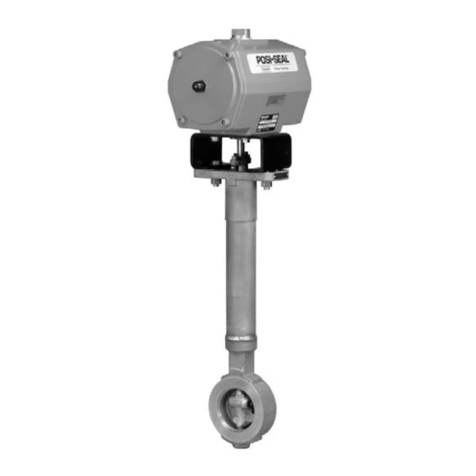
GX Valve and Actuator
Instruction Manual
February 2009
9
and screw the actuator rod (key 22) onto the cap
screw (key 14) finger-tight.
4. Radially align the spring locators in the
diaphragm plate assembly (key 11) with the casing
cap screw holes in the diaphragm (key 10). This will
ensure that the springs do not cover the air path in
the yoke.
5. Torque the cap screw (key 14) to the actuator rod
(key 22) to 65.5 NSm (48.3 lbfSft) and lay this
assembly into the upper diaphragm casing (key 9).
6. Place the actuator springs (key 12 and/or 82)
onto the spring locators in the diaphragm plate
(key 11). See figure 3 and table 2 for proper spring
quantity and arrangement.
DIf the nameplate does not contain spring
information, use the same quantity and arrangement
as originally installed.
7. Remove and replace the actuator rod bushing
(key 19) and actuator rod seal (key 20) in the
actuator yoke (key 8), if necessary.
8. Set the actuator yoke (key 8) down onto the
assembly that is resting in the upper diaphragm
casing (key 9) so that the yoke legs are
perpendicular with the ribs on the top of the upper
diaphragm casing (key 9).
DFor size 225 and 750 actuators, install the 2
long cap screws (key 16) and hex nuts (key 18) 180
degrees apart from each other and in line with the
actuator yoke legs.
DFor size 1200 actuators, install the 4long cap
screws (key 16) and hex nuts (key 18) 90 degrees
from each other, with two of them in line with the
actuator yoke legs.
9. Tighten the long cap screws (key 16) and hex
nuts (key 18), alternating between them to gradually
compress the springs, until the two casing halves
and diaphragm touch.
10. Install the remaining short cap screws (key 17)
and hex nuts (key 18) to the casing.
11. Tighten the actuator casing cap screws evenly
using a cross-tightening procedure. Torque to 55
NSm (40 lbfSft).
12. If you had previously removed the actuator
assembly from the valve, place the actuator
assembly back onto the valve body (key 1). For
standard bonnet constructions (figures 18, 19,
20, and 21), install the body nuts (key 7) and tighten
evenly using a cross-tightening procedure.
See table 4 for torque requirements.
For extension and bellows bonnet constructions
(figures 22 and 23), install the bonnet nuts (key 46)
and tighten evenly using a cross-tightening
procedure. See table 5 for torque requirements.
13. With the valve plug/stem (key 3) in the closed
position (on the seat), thread the stem adjustor nut
(key 27) up until it is at the rated travel (see table 3)
from the actuator rod (key 22). Thread the locknut
(key 28) up against the stem locknut and tighten per
table 6.
14. Stroke the actuator rod until it contacts the stem
adjuster nut (key 27) and install the stem connector
halves and travel indicator (keys 23, 24, and 26) with
the cap screws (key 25). Install the stem connector
halves in the proper orientation so that when looking
at the inside of the stem connector halves, the flats
are down and the beveled surfaces are up.
15. Align the pointer of the travel indicator (key 26)
with the appropriate mark on the travel scale.
16. Tighten the stem connector cap screws
(key 25) to 35 NSm (26 lbfSft).
17. Note: For air-to-close action, the air supply
tubing must be connected to the actuator upper
casing at the air supply connection, see
figure 20 or 21. (If converting from air-to-open to
air-to-close, the tubing will need to be re-routed
to this location).
FIELDVUE DVC2000 Digital Valve
Controller Mounting
This section provides instruction on mounting the
FIELDVUE DVC2000 Series digital valve controller
to the GX control valve. For further detail on the
operation and maintenance of the DVC2000, refer to
the DVC2000 instruction manual.
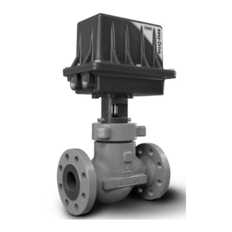
The FIELDVUE DVC2000 Series digital valve
controller mounts directly to an interface pad on the
GX actuator yoke leg, eliminating the need for
mounting brackets (see figure 1). Internal
passageways in the actuator route the pneumatic
output to the actuator casing, which eliminates the
need for external air supply tubing in the air-to-open
(spring-to-close) constructions. (The GX will also
accommodate other valve positioners, using the
NAMUR mounting pads on the side of the yoke
legs.)

