manuals.online logo
Brands
  1. Home
  2. •
  3. Brands
  4. •
  5. elsner elektronik
  6. •
  7. Control Unit
  8. •
  9. elsner elektronik MSG1 compact User manual

elsner elektronik MSG1 compact User manual

Motor Control Unit MSG1 compact 1
Motor Control Unit MSG1 compact • Version: 02.06.2020 • Technical changes and errors excepted. • Elsner Elektronik GmbH • Sohlengrund 16 • 75395 Ostelsheim • Germany • www.elsner-elektronik.de • Technical Service: +49 (0) 7033 / 30945-250
MSG1 compact
Motor Control Unit
1. Description
The Motor Control Unit MSG1 compact controls 230 V drives, e.g. shading or
window motors. The relay at the motor output is a low-wear zero-crossing switch.
The device is equipped with inputs for central control and for a manual switch. The
central input can be set to dead man's switch or lock and is suitable e. g. for timers,
push buttons or control systems. An unlocked twin push button is connected to the
switch input for manual operation. This input is equipped with time-automated but-
tons (step operation/lock).
Functions:
•Outputfora230 V AC drive (Up/Down)
• Use as a central, group and single controller
•Central input up/down 12...28 V DC (with priority) e.g. for switches, controls
• Setting the central control unit to "Dead man" or "Lock". As long as voltage is
present at the central input, the manual operation is blocked
•Manual operation by connecting an unlocked double push-button to the
Input "Local".
Push-button timer automatic: Inching mode (press for less than 1 second):
Drive inches, for example for positioning slats on shutters.
Drive mode (press for longer than 1 second): Drive travels automatically to
the final position
•Lockout inputs for Local Up, Local Down, Central Down
• Direction change pause 1 second
1.1. Deliverables
• Motor control unit
1.2. Technical specification
The product conforms with the provisions of EU directives.
2. Installation and start-up
2.1. Installation notes
Installation, testing, operational start-up and troubleshooting should
only be performed by an electrician.
DANGER!
Risk to life from live voltage (mains voltage)!
There are unprotected live components within the device.
• VDE regulations and national regulations are to be followed.
• Ensure that all lines to be assembled are free of voltage and take
precautions against accidental switching on.
• Do not use the device if it is damaged.
• Take the device or system out of service and secure it against
unintentional use, if it can be assumed, that risk-free operation is no
longer guaranteed.
The device is only to be used for the intended purpose described in this manual. Any
improper modification or failure to follow the operating instructions voids any and
all warranty and guarantee claims.
After unpacking the device, check it immediately for possible mechanical damage.
If it has been damaged in transport, inform the supplier immediately.
The device may only be used as a fixed-site installation; that means only when as-
sembled and after conclusion of all installation and operational start-up tasks and
only in the surroundings designated for it.
Elsner Elektronik is not liable for any changes in norms and standards which may
occur after publication of these operating instructions.
2.2. Safety notice for automatic functions
WARNING!
Risk of injury from automatically moving components!
Parts of the system can be started by the automatic controls
and be a danger to persons.
• No persons may remain in the travelling range of parts
driven by an electric motor.
• Adhere to the relevant building regulations.
• Ensure that the return path/access to the building is not blocked
if spending time outside the building (danger of being locked out).
• Correctly decommission the system for maintenance and
cleaning work.
If there is a power outage, the system does not work. Therefore, shadings should be
moved to a save position if there are anticipated weather conditions, for example, if
this has not already been done by the automatic function (product protection).
If the power supply is removed, the connected drive switches off. When the power
is restored, the consumer remains switched off until a new movement command is
received by the actuator.
2.3. Design of the MSG1 compact / Connection
Connection example 1
Assembly Installation
Protection category IP 20
Dimensions Ø approx. 53 mm, depth approx. 29 mm
Weight approx. 80 g
Ambient temperature Operation -20…+45°C, storage -55…+90°C.
Avoid condensation
Operating voltage 230 V AC
Power consumption Operation maximum 2.0 W
Maximum load Each terminal contact may be loaded with a
maximum of 10 A.
Output 1× 230V drive (Up/Down/PE/N)
Inputs (SELV) 1× Central command (Up/Down/+/-)
1× Manual command via present button (Up/
Down/+/-)
1× Lock Local Down
1× Lock Local Up
1× Lock Central Down
Voltage for inputs 12...28 V DC
Maximum line length 100 m
Lock mode Command at least 1 s
Travel time 4 min
Direction change pause 1 s
Technical specifications and
installation instructions
Article number 70454
Fig. 1
1 Lock inputs: Local down/up, Cen-
tral down
2 Central input (up/down),
Voltage - (12...28 V DC) for inputs
3 Voltage + (12...28 V DC) for in-
puts,
Push-button input local (up/
down)
4 Mode LED
5 Actuator output (down/L/N/up),
Operating voltage (L/N)
1
3
4
5
2
N
PE
L
PE N
Control/
Fig. 2
The internal voltage (9 ... 12
V DC) is used to supply the
inputs. When using several
motor control units which
receive the same central
command, the "-" connec-
tions must be bridged for
potential equalisation.
In this way, a MSG1 com-
pact can supply up to 100
additional motor control
units with power for central
control.
Each terminal contact may
be loaded with a maximum
of 10 A.
Central command
Mains
Central
further MSGS
Button local
230 V AC
EN
Motor Control Unit MSG1 compact 2
Motor Control Unit MSG1 compact • Version: 02.06.2020 • Technical changes and errors excepted. • Elsner Elektronik GmbH • Sohlengrund 16 • 75395 Ostelsheim • Germany • www.elsner-elektronik.de • Technical Service: +49 (0) 7033 / 30945-250
Connection example 2
2.4. Notes on mounting and commissioning
Device must not be exposed to water (rain). This could result in the electronic being
damaged. A relative air humidity of 95% must not be exceeded. Avoid bedewing.
3. Operation
3.1. Central operation
At the central input of the MSG1 compact e. g. an automatic control unit, a timer
or even a normal unlocked twin push button (Up/Down) is connected, to control the
drive connected to the output. As long as voltage is applied to the central input, the
local input is disabled.
If there are "Up" and "Down" movement commands at the central input at the same
time, the drive moves up (secure position).
Set operating mode
The central control unit can be set to the operating modes "Lock" (default) or "Dead
man".
Dead man mode: As long as voltage is present at the input, the drive output is closed
and the engine is running. As soon as there is no voltage left at the input, the drive
output opens and the motor stops.
Lock mode: When voltage is applied to the input for at least 1 second, the drive out-
put closes for 4 minutes and the motor runs for this time. On Command in the op-
posite direction stops the drive.
By simultaneously pressing the Up and Down buttons at the local input, you can
switch between the operation modes:
1. Press the buttons Local-Up and Down simultaneously for 5 seconds,
in order to set the device to readiness for change.
OR
Switch the operating voltage briefly off and on again.
After the mains voltage is connected, the device is also in a state of readiness for
change.
2. The device is now ready for change and it indicates the currently active mode via
the mode-LED.
LED flashes: Dead man mode
LED on: Lock mode.
3. To change the mode, please press Up and Down again for 5 seconds.
4. The device leaves the state of readiness for change after 60 seconds of inactivity
or if you press Up and Down again for a short time.
3.2. Individual operation (local)
The manual individual operation of the drive connected to the output is performed
via an unlocked twin push button at the local input. This input is equipped with time-
automated buttons.
• By a short button stroke, the drive can be exactly positioned (e.g. slats of
blinds).
• At a button stroke longer than 1 second, the drive travels in lock mode to the
end position (motor running time 4 min).
• A short stroke of one of the two buttons stops the travel.
As long as voltage is applied to the central input, the local input is disabled.
4. Disposal
After use, the device must be disposed of or recycled in accordance with the legal
regulations. Do not dispose of it with the household waste!
+
N
PE
L
PE N
Control/
Fig. 3
The voltage for the central
and manual input can be
supplied by an external DC
power supply unit.
Each terminal contact may
be loaded with a maximum
of 10 A.
Central command
Button local
Mains
230 V AC
Central
Power supply further MSGS
DC 12 ... 28 V

This manual suits for next models

1

Other elsner elektronik Control Unit manuals

elsner elektronik RF-MSG-ST IP53 User manual

elsner elektronik

elsner elektronik RF-MSG-ST IP53 User manual

elsner elektronik WS1000 Style User manual

elsner elektronik

elsner elektronik WS1000 Style User manual

elsner elektronik IMSG-UC-2H User manual

elsner elektronik

elsner elektronik IMSG-UC-2H User manual

elsner elektronik IMSG-UC-2H Instruction manual

elsner elektronik

elsner elektronik IMSG-UC-2H Instruction manual

elsner elektronik RF-MSG-ST IP54 User manual

elsner elektronik

elsner elektronik RF-MSG-ST IP54 User manual

elsner elektronik IMSG 230 compact User manual

elsner elektronik

elsner elektronik IMSG 230 compact User manual

elsner elektronik KNX A3-B2 Guide

elsner elektronik

elsner elektronik KNX A3-B2 Guide

elsner elektronik RF-MSG-DST User manual

elsner elektronik

elsner elektronik RF-MSG-DST User manual

elsner elektronik WS1000 Style Reference guide

elsner elektronik

elsner elektronik WS1000 Style Reference guide

elsner elektronik IMSG-UC-4H User manual

elsner elektronik

elsner elektronik IMSG-UC-4H User manual

Popular Control Unit manuals by other brands

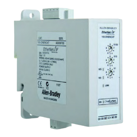
Allen-Bradley 193-DNENCAT user manual

Allen-Bradley

Allen-Bradley 193-DNENCAT user manual

Kidde CO120X quick start guide

Kidde

Kidde CO120X quick start guide

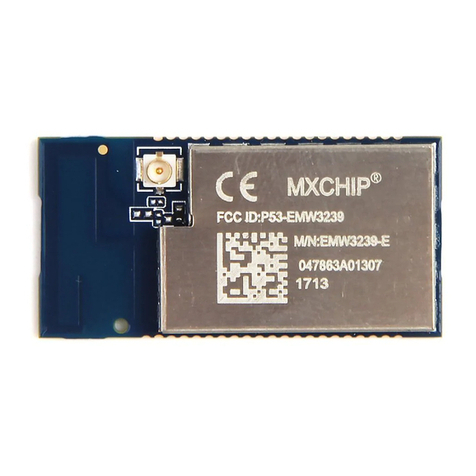
MXCHIP EMW3239 user manual

MXCHIP

MXCHIP EMW3239 user manual

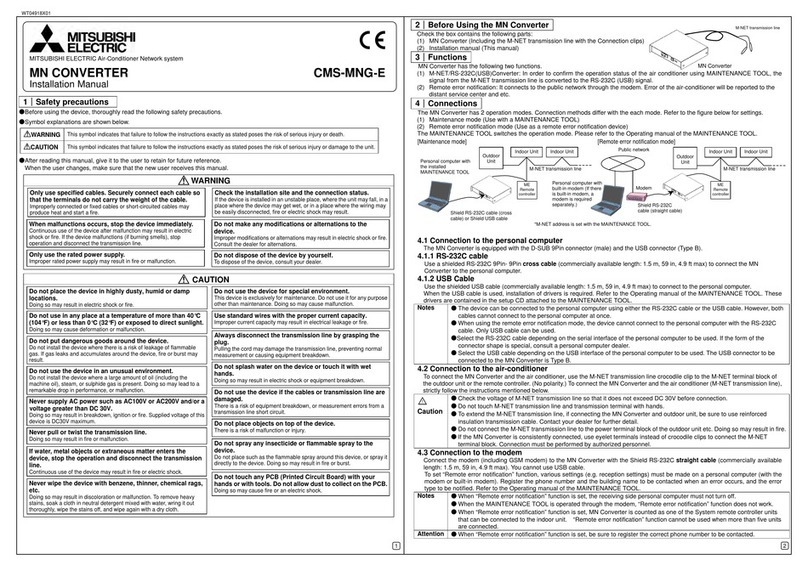
Mitsubishi Electric MN Converter installation manual

Mitsubishi Electric

Mitsubishi Electric MN Converter installation manual

Bull Escala M6-700 reference guide

Bull

Bull Escala M6-700 reference guide

ETAS ES413.1 user guide

ETAS

ETAS ES413.1 user guide

belinus GlasGlas Module installation instructions

belinus

belinus GlasGlas Module installation instructions

Blue BLUE 120 operating manual

Blue

Blue BLUE 120 operating manual

AVCO 1500 Series Installation, operation & maintenance manual

AVCO

AVCO 1500 Series Installation, operation & maintenance manual

JYTEK USB-61900 Series user manual

JYTEK

JYTEK USB-61900 Series user manual

Leonard TM-1520A-DT INSTALLATION ADJUSTMENT SERVICE

Leonard

Leonard TM-1520A-DT INSTALLATION ADJUSTMENT SERVICE

Zehnder Rittling ComfoSense Series manual

Zehnder Rittling

Zehnder Rittling ComfoSense Series manual

SMC Networks EX600-SMJ Series Operation manual

SMC Networks

SMC Networks EX600-SMJ Series Operation manual

Monacor ATT-212/WS operating instructions

Monacor

Monacor ATT-212/WS operating instructions

Measurement Computing E-1608 user guide

Measurement Computing

Measurement Computing E-1608 user guide

Sony HDCU5000 operating instructions

Sony

Sony HDCU5000 operating instructions

RIEGLER 1144 Series instruction manual

RIEGLER

RIEGLER 1144 Series instruction manual

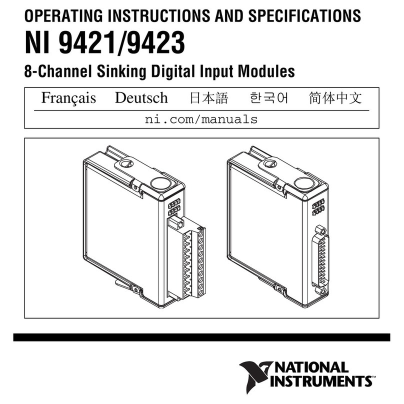
National Instruments NI 9423 operating instructions

National Instruments

National Instruments NI 9423 operating instructions

manuals.online logo
manuals.online logoBrands
  • About & Mission
  • Contact us
  • Privacy Policy
  • Terms and Conditions

Copyright 2025 Manuals.Online. All Rights Reserved.