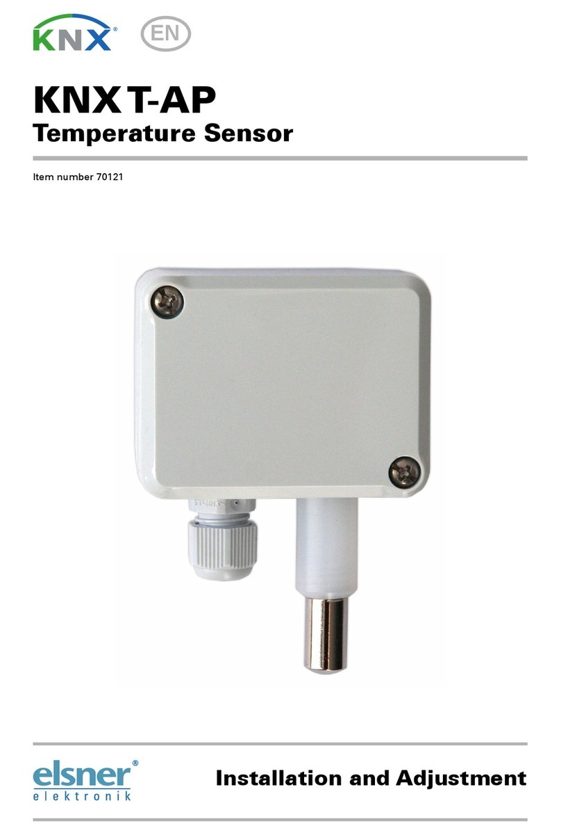
elsner elektronik KNX T-AP Guide

Temperature Sensor
KNX T-AP
Installation and Adjustment

Product Description ..........................................................................................3
Technical specifications................................................................................................. 3
Installation and Commissioning ........................................................................4
Installation position ....................................................................................................... 5
Layout KNX T-AP ........................................................................................................... 5
Connection of the temperature sensor........................................................................... 6
Notes on installation ............................................................................................................................. 6
Maintenance................................................................................................................... 6
Transmission protocol .......................................................................................7
Abbreviations ................................................................................................................. 7
Listing of all communication objects ............................................................................. 7
Setting of parameters......................................................................................11
General settings ........................................................................................................... 11
Temperature measured value ....................................................................................... 12
Temperature threshold values...................................................................................... 13
Temperature threshold value 1 / 2 / 3 / 4 ........................................................................................... 14
Temperature PI control ................................................................................................ 17
Logic............................................................................................................................. 24
AND Logic 1 / 2 / 3 / 4 .......................................................................................................................... 25
Linkage inputs of AND logic ............................................................................................................... 26
OR Logic 1 / 2 / 3 / 4 ............................................................................................................................. 27
Linkage inputs of OR logic .................................................................................................................. 28
KNX T-AP | from software version 0.2.0, ETS programme version 2.0 | Version: 29.03.2012.
Errors excepted. Subject to technical changes.
Elsner Elektronik GmbH Control and Automation Engineering
Herdweg 7 • D-75391 Gechingen • Germany
Phone: +49 (0) 70 56/93 97-0 • Fax: +49 (0) 70 56/93 97-20

2

3
Product Description
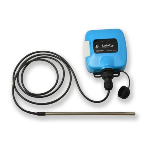
The Temperature Sensor KNX T-AP measures temperature in indoor and outdoor areas.
The sensor can receive an external measured value via the bus and process it with the
own data to an overall temperature (mixed value).
The KNX T-AP provides four switching outputs with adjustable threshold values as well
as additional AND and OR logic gates. The sensor has got a PI controller for heating and
cooling.
Functions:
•Measurement of temperature
•Mixed value from own measured value and external value (proportions can be set
in percentage)
•PI controller for heating (one or two step) and cooling (one or two step)
•4 switching outputs with adjustable threshold values (Threshold values can be
set by parameter or via communication objects)
•4 AND and 4 OR logic gates with each 4 inputs. Every switching incident as well
as 8 logic inputs (in the form of communication objects) may be used as inputs for
the logic gates. The output of each gate may optionally be configured as 1 bit or 2 x
8 bits
Configuration is made using the KNX software ETS. The programme file (format VD2)
and the manual can be downloaded from the Elsner Elektronik homepage on
www.elsner-elektronik.de in the “Service” menu.
Technical specifications
Housing: Plastic material, sensor sleeve metal
Colour: Grey
Mounting: On-wall
Protection category: IP 65
Dimensions: approx. 65 x 93 x 38 (W x H x D, mm)
Weight: approx. 70 g
Ambient temperature: Operation -30…+85°C, Storage -55…+125°C
Operating voltage: KNX bus voltage
Bus current: max. 5.5 mA,
max. 15 mA when programming LED is active
Data output: KNX +/- bus terminal plug
BCU type: Own micro controller
PEI type: 0
Group addresses: max. 184
Allocations: max. 184

4
Communication objects: 80
Measurement range: -40…+80°C
Resolution: 0.1°C
Accuracy: ±1°C at -10…+85°C
±1.5°C at -25…+150°C
The following standards have been considered for the evaluation of the product in terms
of electro magnetic compatibility:
Transient emissions:
•EN 60730-1:2000 Section EMV (23, 26, H23, H26) (threshold category: B)
•EN 50090-2-2:1996-11 + A1:2002-01 (threshold category: B)
•EN 61000-6-3:2001 (threshold category: B)
Interference resistance:
•EN 60730-1:2000 Section EMV (23, 26, H23, H26)
•EN 50090-2-2:1996-11 + A1:2002-01
•EN 61000-6-1:2004
The product has been tested for the above mentioned standards by an accredited EMV
laboratory.
Installation and Commissioning
Installation, inspection, commissioning and troubleshooting
of the sensor must only be carried out by a competent electrician.
Disconnect all lines to be assembled, and take safety precautions against accidental
switch-on.
The sensor is exclusively intended for appropriate use. With each inappropriate change
or non-observance of the instructions for use, any warranty or guarantee claim will be
void.
After unpacking the device, check immediately for any mechanical damages. In case of
transport damage, this must immediately notified to the supplier.
If damaged, the sensor must not be put into
operation.
If an operation without risk may supposedly not be guaranteed, the device must be put
out of operation and be secured against accidental operation.
The sensor must only be operated as stationary system, i.e. only in a fitted state and after
completion of all installation and start-up works, and only in the environment intended
for this purpose.

5
Elsner Elektronik does not assume any liability for changes in standards after publication
of this instruction manual.
Installation position
The sensor is designed for surface mounting. When selecting an installation location,
please ensure that the measurement results are affected as little as possible by external
influences. Possible sources of interference include:
•Direct sunlight
•Drafts from windows and doors
•Warming or cooling of the building structure on which the sensor is mounted, e.g.
due to sunlight, heating or cold water pipes
•Connection lines which lead from warmer or colder areas to the sensor
Temperature variations from such sources of interference must be corrected in the ETS
in order to ensure the specified accuracy of the sensor (temperature offset).
For outdoor installation it must be ensured that a 60 cm gap is left below the sensor in
order to prevent it from being snowed during snowfall.
The sensor must be mounted vertically. The measurement probe and the cable outlet
must point downwards.
Layout KNX T-AP
Fig. 1: Opened casing, board Fig. 2: Rear view with dimensioning of
openings for mounting
1 Slot for KNX terminal +/-
2 Programming button for teaching the instrument
3 Programming LED
4 Cable entry with threaded joint
5 Temperature sensor tip

6
Connection of the temperature sensor
Remove the screwed on cover. Lead the KNX bus connection cable through the cable
entry on the bottom of the casing and connect the bus +/- to the terminal provided for
this purpose. Screw the cover back on.
Notes on installation
Do not open the temperature sensor if penetration of water (rain) is likely: Only a couple
of drops could damage the electronic.
Maintenance
The temperature sensor should regularly be checked for dirt and cleaned, if required.
Due to safety reasons, the sensor should always be
disconnected from the bus current when performing
maintenance and cleaning works (e.g. by deactivating/
removing fuse).

7
Transmission protocol
Abbreviations
Flags:
C Communication
R Read
W Write
T Transmit
U Update
Listing of all communication objects
No. Name Function DPT Flags
0 External measured value for temperature Input 9.001 C W
1 Internal measured value for temperature Output 9.001 C R T
2 Total measured value for temperature Output 9.001 C R T
3 Request min./max. measured value for
temperature
Input 1.017 C W
4 Minimum measured value for
temperature
Output 9.001 C R T
5 Maximum measured value for
temperature
Output 9.001 C R T
6 Reset min./max. measured value for
temperature
Input 1.017 C W
7 Temperature sensor malfunction Output 1.001 C R T
9 Temp. threshold value 1: Absolute value Input / Output 9.001 C R W T U
10 Temp. threshold value 1: (1:+ | 0:-) Input 1.006 C W
11 Temp. threshold value 1:
Switching output
Output 1.001 C R T
12 Temp. threshold value 1:
Switching output block
Input 1.006 C W
13 Temp. threshold value 2: Absolute value Input / Output 9.001 C R W T U
14 Temp. threshold value 2: (1:+ | 0:-) Input 1.006 C W
15 Temp. threshold value 2:
Switching output
Output 1.001 C R T
16 Temp. threshold value 2:
Switching output block
Input 1.006 C W

8
No. Name Function DPT Flags
17 Temp. threshold value 3: Absolute value Input / Output 9.001 C R W T U
18 Temp. threshold value 3: (1:+ | 0:-) Input 1.006 C W
19 Temp. threshold value 3:
Switching output
Output 1.001 C R T
20 Temp. threshold value 3:
Switching output block
Input 1.006 C W
21 Temp. threshold value 4: Absolute value Input / Output 9.001 C R W T U
22 Temp. threshold value 4: (1:+ | 0:-) Input 1.006 C W
23 Temp. threshold value 4:
Switching output
Output 1.001 C R T
24 Temp. threshold value 4:
Switching output block
Input 1.006 C W
25 Temp. control: Switching object
(0:heating | 1:cooling)
Input 1.002 C W
26 Temp. control: Target value current Output 9.001 C R T
27 Temp. control: Blocking object Input 1.006 C R W
28 Temp. control: Target value, day heating Input / Output 9.001 C R W T U
29 Temp. control: Target value, day heating
(1:+ | 0:-)
Input 1.002 C W
30 Temp. control: Target value, day cooling Input / Output 9.001 C R W T U
31 Temp. control: Target value, day cooling
(1:+ | 0:-)
Input 1.002 C W
32 Temp. control: Act. variable heating
1. stage
Output 5.001 C R T
33 Temp. control: Act. variable heating
2. stage
Output 5.001 C R T
34 Temp. control: Act. variable heating
2. stage
Output 1.001 C R T
35 Temp. control: Act. variable cooling
1. stage
Output 5.001 C R T
36 Temp. control: Act. variable cooling
2. stage
Output 5.001 C R T
37 Temp. control: Act. variable cooling
2. stage
Output 1.001 C R T
38 Temp. control: Night lowering activation Input 1.003 C W

9
No. Name Function DPT Flags
39 Temp. control: Target value heating,
night
Input / Output 9.001 C R W T U
40 Temp. control: TargetV heating, night
(1:+ | 0:-)
Input 1.002 C W
41 Temp. control: Target value cooling,
night
Input / Output 9.001 C R W T U
42 Temp. control: TargetV cooling, night (1:+
| 0:-)
Input 1.002 C W
43 Temp. control: Status heating 1
(1=ON | 0=OFF)
Output 1.001 C R T
44 Temp. control: Status heating 2
(1=ON | 0=OFF)
Output 1.001 C R T
45 Temp. control: Status cooling 1
(1=ON | 0=OFF)
Output 1.001 C R T
46 Temp. control: Status cooling 2
(1=ON | 0=OFF)
Output 1.001 C R T
47 Temp. control: Window status
(0: closed | 1: open)
Input 1.019 C W
78 Logic input 1 Input 1.006 C W
79 Logic input 2 Input 1.006 C W
80 Logic input 3 Input 1.006 C W
81 Logic input 4 Input 1.006 C W
82 Logic input 5 Input 1.006 C W
83 Logic input 6 Input 1.006 C W
84 Logic input 7 Input 1.006 C W
85 Logic input 8 Input 1.006 C W
86 AND logic 1: 1 bit Output 1.001 C R T
87 AND logic 1: 8 bit output A Output 5.010 C R T
88 AND logic 1: 8 bit output B Output 5.010 C R T
89 AND logic 2: 1 bit Output 1.001 C R T
90 AND logic 2: 8 bit output A Output 5.010 C R T
91 AND logic 2: 8 bit output B Output 5.010 C R T
92 AND logic 3: 1 bit Output 1.001 C R T
93 AND logic 3: 8 bit output A Output 5.010 C R T
94 AND logic 3: 8 bit output B Output 5.010 C R T

10
No. Name Function DPT Flags
95 AND logic 4: 1 bit Output 1.001 C R T
96 AND logic 4: 8 bit output A Output 5.010 C R T
97 AND logic 4: 8 bit output B Output 5.010 C R T
98 OR logic 1: 1 bit Output 1.001 C R T
99 OR logic 1: 8 bit output A Output 5.010 C R T
100 OR logic 1: 8 bit output B Output 5.010 C R T
101 OR logic 2: 1 bit Output 1.001 C R T
102 OR logic 2: 8 bit output A Output 5.010 C R T
103 OR logic 2: 8 bit output B Output 5.010 C R T
104 OR logic 3: 1 bit Output 1.001 C R T
105 OR logic 3: 8 bit output A Output 5.010 C R T
106 OR logic 3: 8 bit output B Output 5.010 C R T
107 OR logic 4: 1 bit Output 1.001 C R T
108 OR logic 4: 8 bit output A Output 5.010 C R T
109 OR logic 4: 8 bit output B Output 5.010 C R T
117 Software version Output 217.001 C R T

11
Setting of parameters
General settings
Transmission delays after
power-up and programming for:
Measured values 5 s
•
10 s • 30 s • 1 min • …
•
2 h
Threshold values and switching outputs 5 s
•
10 s • 30 s • 1 min • …
•
2 h
Target values and actuating variables 5 s
•
10 s • 30 s • 1 min • …
•
2 h
Logic outputs 5 s
•
10 s • 30 s • 1 min • …
•
2 h
Maximum telegram quota 1
•
2
•
3
•
5
•
10
•
20 Telegrams per second
Use malfunction object No
•
Yes

12
Temperature measured value
Temperature offset in 0.1°C -50 … 50
Use external measured value for temperature No
•
Yes
If no external measured value is used:
Use external measured value for temperature No
Temperature measured value
•
do not send
• send periodically
• send in case of change
• send in case of change and periodically
From change of
(only if sending “in case of change”)
2%
•
5%
•
10%
•
25%
•
50%
Send periodically all
(only if sending “periodically”)
5 s
•
10 s • 30 s • 1 min • …
•
2 h
Use min. and max. temperature values
(Values are not maintained after reset)
No
•
Yes
If an external measured value is used:
Use external measured value for temperature Yes
Ext. temperature measured value proportion
of the total measured value
5% … 100% (in steps of 5%)

13
Internal and total measured value for
temperature
•
do not send
• send periodically
• send in case of change
• send in case of change and periodically
All following settings refer to the total measured value
From change of
(only if sending “in case of change”)
2%
•
5%
•
10%
•
25%
•
50%
Send periodically all
(only if sending “periodically”)
5 s
•
10 s • 30 s • 1 min • …
•
2 h
Use min. and max. temperature values
(Values are not maintained after reset)
No
•
Yes
Temperature threshold values
Use temperature threshold value 1 /2 / 3 / 4 No
•
Yes

14
Temperature threshold value 1 / 2 / 3 / 4
Temperature threshold value:
……………………………
Temperature threshold value standard per Parameter • Communication object
If the threshold value is set per Parameter:
Temperature threshold value standard per Parameter
Temperature threshold value in 0.1°C -300 … 800
Hysteresis of the threshold value in % 0 … 50
If the threshold value is set per Communication object:
Temperature threshold value standard per Communication object

15
The value communicated last shall be
maintained
•
not
• after restoration of voltage
• after restoration of voltage and programming
(Do not use for first commissioning)
Start temperature threshold value in 0.1°C
valid until 1.communication
(only if the value communicated last is “not”
maintained or “after restoration of voltage”)
-300 … 800
Type of threshold change for temperature
•
Absolute value
• Increment/decrement
Step size
(only with “Increment/decrement”)
0.1°C
•
0.2°C
•
0.3°C
•
0.4°C
•
0.5°C
•
1°C • 2°C
•
3°C • 4°C • 5°C
Hysteresis of the threshold value in % 0 … 50
Temperature switching output:
……………………………
Output is at
(TV = temperature threshold value)
•
TV above = 1 | TV
–
Hyst. below = 0
• TV above = 0 | TV – Hyst. below = 1
• TV below = 1 | TV + Hyst. above = 0
• TV below = 0 | TV + Hyst. above = 1
Switching delay from 0 to 1 none
•
1s
•
2 s • 5 s • 10 s • …
•
2 h
Switching delay from 1 to 0 none
•
1 s
•
2 s • 5 s • 10 s • …
•
2 h
Temperature switching output sends
•
on change
• on change to 1
• on change to 0
• on change and periodically
• on change to 1 and periodically
• on change to 0 and periodically
Send temperature switching output
in the cycle of
(only if sending “periodically”)
5 s
•
10 s • 30 s • 1 min • …
•
2 h
Blocking:
……………………………
Use block of the temperature switching output No
•
Yes
Evaluation of the temperature blocking object
•
if value 1: block | if value 0: release
• if value 0: block | if value 1: release
Wert des Sperrobjekts
vor 1. Kommunikation
0 • 1
Behaviour of switching output
with blocking
•
do not send telegram
• send 0
• send 1

16
The behaviour with release of the switching output depends on the value of the
parameter “Temperature switching output sends …” (see ”Temperature switching
output”)
Value of parameter
“Temperature switching output sends”:
Setting options
“
Behaviour of switching
output with release”:
on change
•
do not send telegram
• send status of the switching output
on change to 1
•
do not send telegram
• if switching output = 1 Îsend 1
on change to 0
•
do not send telegram
• if switching output = 0 Îsend 0
on change and periodically send status of the switching output
(no selection)
on change to 1 and periodically if switching output = 1 Îsend 1
(no selection)
on change to 0 and periodically if switching output = 0 Îsend 0
(no selection)

17
Temperature PI control
Use control No
•
Yes
If the control is in use:
Control general:
……………………………
Type of control
•
One-stage heating
• Two-stage heating
• One-stage cooling
• One-stage heating + one-stage cooling
• Two-stage heating + one-stage cooling
• Two-stage heating + two-stage cooling
Behaviour of the blocking object with value
•
1 = block control |
0 = release control
• 0 = block control |
1 = release control

18
Value of the blocking object
before 1. communication
0
•
1
Send actuating variables
•
on change
• on change and periodically
Transmission cycle
(only if sending „periodically“)
5 s … 2 h
Status object/s send
•
on change
• on change to 1
• on change to 0
• on change and periodically
• on change to 1 and periodically
• on change to 0 and periodically
Transmission cycle
(only if sending „periodically“)
5 s … 2 h
Controller target value:
……………………………
Target value setpoint per Parameter • Communication object
If the target value is set per Parameter:
Target value setpoint per Parameter
Target value in 0.1°C -300 … 800
If the target value is set per Communication object:
Target value setpoint per Communication object
The value communicated last shall be
maintained
•
not
• after restoration of voltage
• after restoration of voltage and programming
(Do not use for first commissioning)
Start target value in 0.1°C
valid until 1.communication
(only if the value communicated last is “not”
maintained or “after restoration of voltage”)
-300 … 800
Limitation of object value (min) in 0.1°C -300 … 800
Limitation of object value (max) in 0.1°C -300 … 800
Type of the target value change
•
Absolute value
• Increment/decrement
Step size
(only with “Increment/decrement”)
0.1°C
•
0.2°C • 0.3°C
•
0.4°C • 0.5°C • 1°C • 2°C •
3°C • 4°C • 5°C

19
Heating control / Heating control 1. stage
(Appears only if heating control is used):
……………………………
Setting of the controller by
•
preset applications
• controller parameter
Application
(only if controller is set by “preset
applications”)
•
Hot water heating
• Floor heating
• Fan convector
• Electrical heating
Maximum actuating variable is reached at
target/actual difference of
(Attention: Can only be adjusted if “Setting of
the controller by controller parameter”)
1°C • 2°C • 3°C • 4°C • 5 °C
Re-setting time in mins
(Attention: Can only be adjusted if “Setting of
the controller by controller parameter”)
1 … 255
If blocked, the actuating variable shall
•
will not be sent
• send a specific value
Value in %
(not if a specific value is sent)
0 … 100
Other manuals for KNX T-AP
1
Table of contents
Other elsner elektronik Temperature Controllers manuals
elsner elektronik
elsner elektronik KNX eTR 101-BA2 Guide
elsner elektronik
elsner elektronik KNX T-UN 130 Guide
elsner elektronik
elsner elektronik Cala KNX T 101 User manual
elsner elektronik
elsner elektronik Arexa 230V Window Control Guide
elsner elektronik
elsner elektronik KNX T-AP Guide

elsner elektronik
elsner elektronik Cala KNX T 101 User manual
elsner elektronik
elsner elektronik KNX eTR 101 User manual

elsner elektronik
elsner elektronik KNX eTR 201 Sunblind User manual
elsner elektronik
elsner elektronik 20552 User manual
elsner elektronik
elsner elektronik KNX TH65-AP User manual
