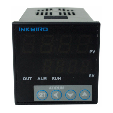
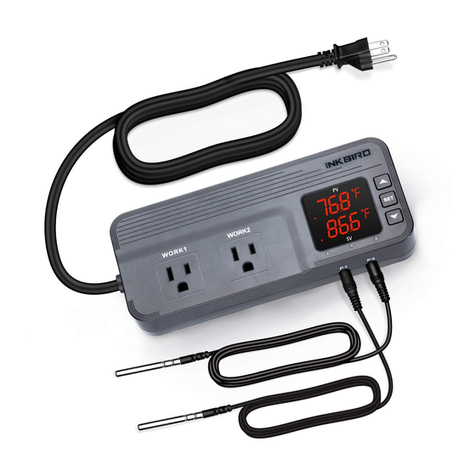
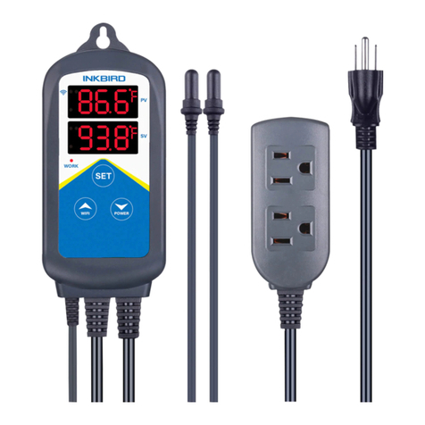
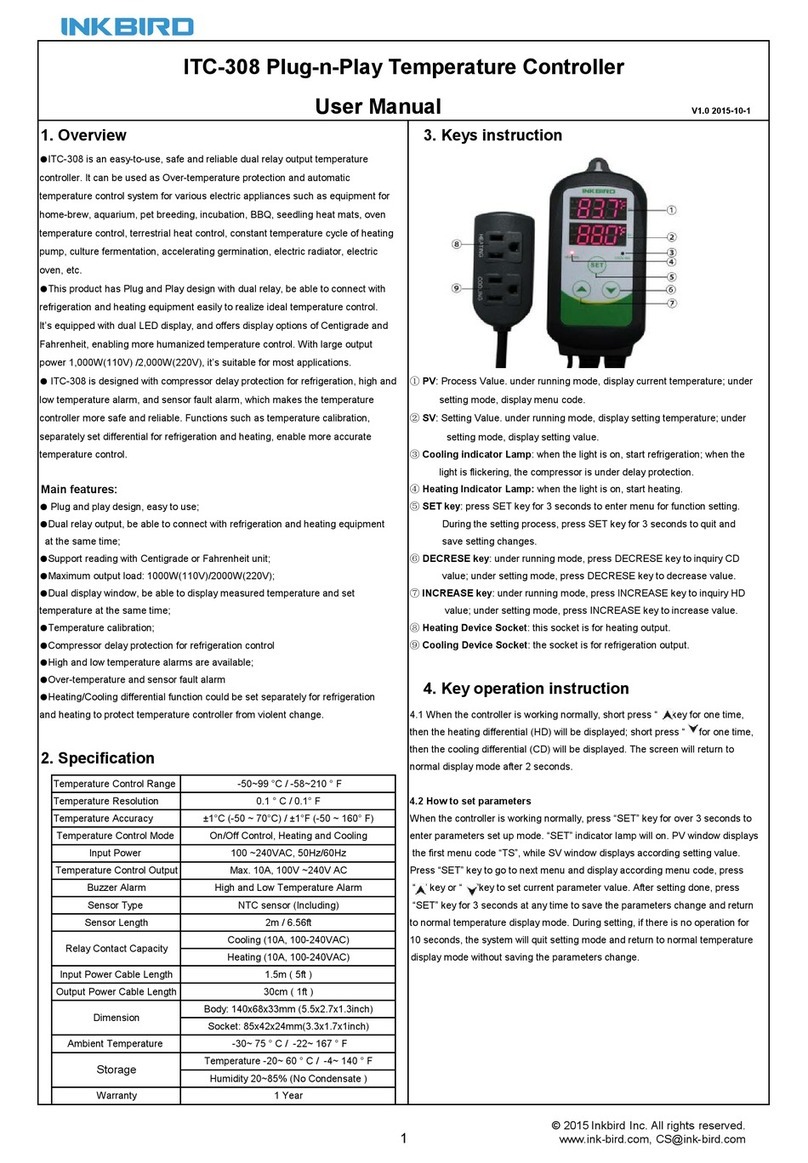
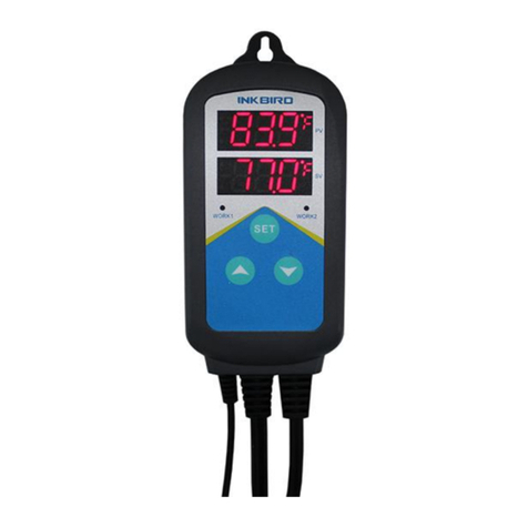
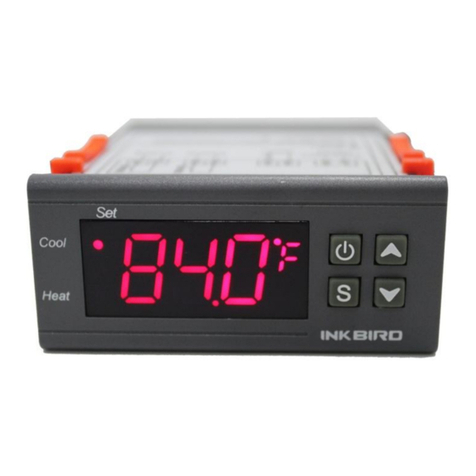
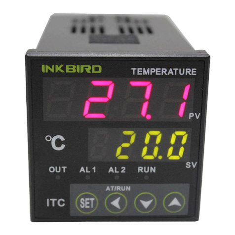
Ink Bird ITC-100 User manual

pr
R@d the instructis manual €refully befqe 6irE, for right applicato ad mtnte.rc.
I s*ty Pracautins
.h lE E -r -n rE sFtcdin.
.l> - 5 L- a EGr i- poffi is being supplied [}iE $ !E, r-zdy iaa h iriry dE b dcEEa shL
rlb a & ic - -, ie csdngs, tr fire metallic straip r -Es fm t*in b qE tE Fodrl tLtg s nEy
..@l rra - &-.1d, frc, tr mltunclion.
.Ib ru E !D Fond fE rtid to flammHe or explGive gE- firr*E' iiry tm e$Gir nEy @r:ody @.
. i&s ,kilL, moq a rlFi tE Foduct q brci any of the ird pG" El.lh Sfioctq fc, a f,cfiraf,on [Ey @iqdly ffi.
. r rhe dripln Elays aB 6ed pd their life aeedancy, cont a tgllumlry-ery4rytur afiEt6. dEiAbfi.iib'
-*effiril*.n;.fr],lj.J"r-dandelectrjcallifeThe|ife-expectancyofoutputrelayswries
@nsidembly with the output l@d and switdr sditire.
! uain Features
. Frcnt Panel Dimension: DlNl/16 48mm(L)x48mm(W), CubI sia: 45x45mm
. Suppod Multiple Themocouples and R6istance Sens (K, S, We, T, E, J, B, N, CU5o, PTl00)
. W& Coflrolling Range: -50-l3OOf (K sn$r)
. tfoh A@lEcy of Displaying and Contrclling 0.1f, A@Eq, oI Msuremert +0.2%FS
. PID aj ON/OFF Cryttlol Mode, High Standard Sef-adj6{irE Funclim
. tr-tr O.G il, Alrq the
, -IrF f-l tu Ih tdrftrre :-
.Tb ffi ffi rd hQEnt Offi d tE ffiument.EHe tp LtrE-tsm MTry
. Hgh triEE, O.39- htE LED dsCay, Ara-gtsE Fd
. Built-in Siitdlr PoE St+dy, Vlfide Vofage Rafge nd lfl-povrer Cor6umFin
Specification
I. Units: Deg@ Cek*E (<!OO(rc)
. Pwer Supply Voltage: AC IOO-2/+(}V ltOI 5ol6o1ts
AC r2-24VtrOX 50/60t-E
DC 12-24V +',tox
. OpeEting voltage 6ge; _85-110%.+lsted voltagel
. Power Consumption: Apprcx. 5VA (IOO-24oVAC)
,Oppu- 4VA (2-21VAC)
tIpE 3W (.t?-24V8)
.ryk
.EhlfEry
F: 4 dgld 9.9dn 1r{lr Red LED LeUEs
SY: 4 Qld Em trtlr ea LED LeGs
+o-zrFs o-rt (<rmt) ' rt (> rooot)
.Id d S+C. OJS
. TG.TIEEIE CiFE{uE O-sdb
. Main OuEi: Reby Coda.r ollFrt (ITC-IOoR): AC25oV 3A (R6is1ire l€d) ON/NC.
Alam 1 AC25OVi 3A ( Resistive load) ON,/NC.
Voltage Pulses Output (|TC-1OOV): D'C 12V. lOmA;
Alam I AC25OV 3A ( Resistive l@d ) ON,/NC
. Ufe Exp€ctancy of Relay: Mechani€l > 1O,OO0,OO0 opsatim Eletical > 10,000,000 operations
. Weigtt: Approx. 14Og
. ENilmtd Conditions: -10-55"C (no icy or qdqetim), RH 35-85X Humidity
. Sbrage Tqperature: -25-65"C (no icy or qrdsstion)'
. D& Sorqe: IOyBE
. Mqrrthg ll€fiod: Fl6h mounting and sw Eminals

I
r:
h:
";
,f.s'
! conne"rion
o O-.acao{uilit:r!)
v
l.pch lhe instrument into the hole of panel and insen mounting Eacket from back side, ensure that there are no gaps
batE] the pand and mounting bEcket, and then screw cap &rvn.
* r- CE lE l: ffi E operatre srqld rpt be exceed-tE qT{Sg- wotirfs tempemture, specially when _installed*__.
*- ir E c*rnErs
a Corxtccfon
Output
r.&i,{,r*!
Front Panel
o PV Process Value
Measured Value/Mode Value
. SV Set Vdoe
Set VahE/'Mode Context Value
Slatrs lrsplay Lts{.
OUT: Output pil<it lbmp
ALI: Alarml pilot lamp
AL2: Alarm2 pilot lamp
RUN: Manual pilot lamp
o Up Key: lncrease lhe value in setting, Keep pressing can increase value quick.
. Down Key: Decrease the value in setting, Keep pressing can increase value quick.
o Move Key: When setting temperature value or parameter, press
Key to switch to the value needed
. Self-Adjustment Key: When SV/PV at normal display, keep pressing the
' (4)) Key more than 25 to start or end self-adjusting function,
o Shift Key: When SV/PV at normal display, press " (( " Key less than lS to
shift between automatic and manual control modes.
. SET Key : When SV/PV at normal display, press the SET key to check PV and
SV value, keep pressing it more than 2 seconds can access parameter setting mode.
I
ft
f|artEg EecE
LT;;-S"
rttl
l*s+8H

OprdotPloc
r lnput(Tabl)
.--qror
.- Alalm Function settlng(rab2)
II: Carffi Abrm Sefiim: ChG Al.P ValLEs tDm Table2
rd affi trem up, set in ALP.
lnput Typg Inptn Value Measuring R+gE
IfErlrde
K0-50-1300:q
S-s0- 1700"c-
2-0- 2300"c
T3-2000-350"c
E1 O-1000"c
J5o-to00"c
B50-t800'c
x7O-13O0'c
&*r clr50 ?o -50-t 5cfc
Plfrm E*re PTIOO 2l -200"-600'c
Alarm Output Alarm Type ALP Value
AL1 Output
Upper Alarm Limit 0
Lower Alarm Limit 0
Maximum Deviation Alam 0
Minimm Dwiatbn Alam 0
a2 orar (hF Alam Umit I
Lffi Aam Unnt 2
litilinm Dsrirtir Alam 4
Hidmrn DevirtiIl Am 8
SV Display Explain Remedy
0ffrL
( orAL)
lnput Sensor Selecled EnoI lnpd lhe conect value consistenl with parameters of sensor
Signal Wir6 Connected Enor Cor€d the Connecting Signal Wire
Sensor Fault Ched( the sensor
. Operating lnstruction
. Afu rffi-m F / ffi dsdays alHt mesurcd relue and SV scrs disdays orent st yalue. the instrument is in
f - *I- f pYV E ffi 'dL- dt-"E, it meils H irEa dr t or oa ral3(r serEr b open
rit)c il s.ttr b iE.rcclwEr tlsE b &m odprt, Sl/ screen displays cfiaracrer rdaEd wih dam: H|AL (Upper
lEil lirt), tdl(tc Afnrn uEii),CnL(Iainrn Deviatim Alarm),dLAL(Minimum Dwiation Alam).
. GEding OItrt Vdrr: lGy (m nse than lS), f SV sdeen displays "A",( e.s, f, r00), the status
b atffiic cqtEd o"qrq f $r' &rm dsCay 'll',( e.g.; l'; lB0 I,Ure status is manuat controt output.
. Aub/iJkual $riHr: Press 'l't(eIl ko nrn ilEr ls),can switd tle insrument betffir automalic @ntrol and manual
corlrrol staEs. ln autoflEtic conrol sffits, RtN pad lanp is off; in manual control $ahB, RUN 6ibt lamp is on. (Remarks:
lf status ot setling'function is '2: tlo rmnr,al", it cannot operate like this.)
o Temperature Setting: J,Vhen SV screen dlseays setting ,pu1 nress "ii_!"y<or "YlBllcalliry".:,9j or decre€se) sotting
value. Press u(" k"y ,"n move the place of update data. h'keep pressing il^" Key(or"v"Key), can set the value quick,
o Slart the Sdf-aluSirE Furctirx: Al fre fiEf -trre r, please E sdf-adjEting funcrion to de(emine the mntrol paEmetffi
(fa5o, P td T Farg), so I can &il ibd dtrolling. l(eep FessiE the '(" tey for re than 25, SV screen
+: 'Af- *dt (ffi Pt ), tE insfiument is in set-adlEli{ stats. ln tis stilrs5 tlE iEfLrEnt will
-
6 "il-.f V 2 - 5 t|t E{afiorts, then it $l trn di PID dtd f-anehf afrndicdy (M50, P
d I arrr*). It iEhEa - Erm b PID alomatic cmfd $ats at lhe crd of aqusment by 2 - 5 times
Gca{arsr aEr I f, lm at Pfi) c[d Fan*r automaticdly (MsO, P and T pf,fier). The insfurEm wfll rctum
r€tutn b PID atumdic cond stafrrs at fte sd d sdf-adiustmenL lf us€r urant to quit in lhe mlse of self-adjusting,
keep pressing '(" key for more than 2S, till "AT1 character in the sV screan disappgars.
o Attontion: lf user wants to use self-adjusting function again after first using, user needs to set "CtrL" to be "2" to start
it (more information please check "Parameter Setting and Defining" ).The parameter values of adjusting @ntrol are not the
the same at the different setting temperatures, so please execute self-adjusfiEnt at the most @mmon setting value ol the system.
f the s€,ning wlues dnnge often, user can moddate with the median.

! P"r"..t"r Setting and Defining
Afrer porer-o, keep frsing tE 'SET' key fd more than 25 to entd sding mode. User can uss" " Key(or "v"Key) to
sat the vatE- Afis 6risfi[, F6 'SET- kry to mfim 6nd enter next ftrdin etting. PVISV scEEn will be ln normal normal
dsptay d6 gi!o.
tle l, dEE re nff r'-E it $-!C trEb, the iffimdt wiu * 6sn Blc admati€lly aftd no opeElid fd mor€
brll sEa6, ri rh b lEd .laa5-
Functlon S.ldnd D€scrlptlon Sottlng Rrrlee Unlt Remarks Factory Default
Cod. Name
HIAL JoDer Alarm Limil - 1 999-+9999 c9999
,LoAL Alarm timit - I 999- +9999 c-1999
,4 '4 dHAL Maximum Deviation Alam o-9999 c9999
duL Minimum Deviation Alarm o- 999 9 c9999
dF Hysteresis 0- 200.o o.1c o.3
EtrL CtrL Control Outpul O: ON./OFF
1/3t PID
2:Self-adjEurEt
3
: qn v5: o-9999 o.1c o: Cancel 1000
P-Etd o.-9999 o.ots'c 500
ITm l,-9999 Sr20
c{ bfrd Fsiod l-120
nStr lfr Sqs o-42 TaUe Io
PdP )gcimd Pdnt Podtioo o-3
dL Et Lffi Limit vdE - I 999- +9999 1 Dlgital o
dtH #t ,Ei uE umit valE - I 999- +9999 1 Digital tooo
qr sc =g- Ca*b.athn -199-+999 o
oPl oPl frprr fao.te O./2: Tire Duty
l: O-lOnA o
orL O9a )uout Lffi Umit o-220 lx o
oph }fu Uffi LiMit o-220 1% loo
ALP \lem Fundion O:31 * Table.2 o-
rF CF Function 2 | H@tq
3:Coda 2
Hddr Addr \ddBs o-63
hdBeud laud Rate o-4EOO 9600
dL dt nput Oigital Filter o-20 Filter Effect o
r un run lun Mode O: lrldEl
I ! A.ttEtoc
2: 15 Lanual
2
oc LOC -@k Functlon o-991t 40
EP I
EPE EPI. EP8 U*r-defined PaEM* Sdd ay Parameter
tm Iis Table Ex@pt LOC
ad EPI-EP8 none
*\r
-' . ttts-ffned Pa,il€bc tn the rcss of setting paEm€tE6, Itc display mod€s of last eight parameteE sE dFfrsren@ frcm the
previous. PV scre€n displays prcmpt EP1 - EP8, SV screen dsdays various prompts oI technical paEmeteE Setting (e.9. HiAL,
HiAL, LoAL, dHAL and so on). Press " " Key<or'v"Key) , The tehnical parameters in SV scren will be listed in proper
order as the above paramoteE table. After that, press "SET" key @nfim and enter next sding. "none" needs to be set if
user don' t need to use the user-defined parameter, Press 'SET" key lo set these 8 user-defined paramete6 till sll to be
sett and then retum to normal status.
. Datalock (LOC): When the seting values ot LOC a@ not "2" , "4O" or "8O8", the instrument only allds to set O-8
selt-defined pa€meters and LoC paEmetffi themselves, Usr @n s€t
all paEffi q{y s,tE sdtrE Loc vde is "2", '/+o" d "8o8". Debils ae 6 follM:
L@-O, Tmpe.stE ssdim v*E ad EPI-EPB @n be Mmped.
Loc= 1 , Data @n not be Bmpe4 oly €n be ch@ked. ( Exccpt LOC par6msts )
Loc-z, 40, 808, all oI paEmet* €n be revamped. f-----a-----
i rNxarno recH.co.,LTD. i
i www.ink-bird.com I
i - Tl' I ::tt"-':gl ii :Err - j
Other manuals for ITC-100
4
Table of contents
Other Ink Bird Temperature Controllers manuals

Ink Bird
Ink Bird ITC-106 User manual

Ink Bird
Ink Bird ITC-1000 User manual

Ink Bird
Ink Bird ITC-308 User manual

Ink Bird
Ink Bird ISC-007BW User manual

Ink Bird
Ink Bird ITC-306T User manual

Ink Bird
Ink Bird ITC-1000F User manual

Ink Bird
Ink Bird ITC-308 User manual

Ink Bird
Ink Bird ITC-306A User manual

Ink Bird
Ink Bird IHC-230 User manual

Ink Bird
Ink Bird ITC-1000 User manual