manuals.online logo
Brands
  1. Home
  2. •
  3. Brands
  4. •
  5. Alarm SAF
  6. •
  7. Power Supply
  8. •
  9. Alarm SAF PS5-M Series User manual

Alarm SAF PS5-M Series User manual

Note - This Quick Installation Guide is intended to give the basic information needed to install and configure a PS5-M power supply board. For full instructions and specifications, please consult the full PS5-M
Installation Instructions, Document Number 52-375 which can be downloaded at www.alarmsaf.com
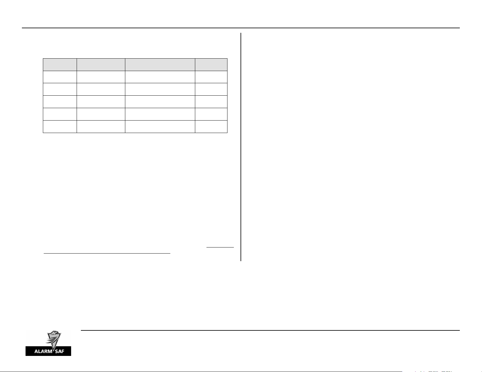
Terminal Connections
See Document 52-375 for detailsAccessory Board ConnectionABC
Common Fault Relay Normally ClosedCOM FLT NO
Common Fault Relay Normally OpenCOM FLT NC 1A @ 28VDC
Common Fault Relay CommonCOM FLT C
AC Fault Relay Normally ClosedAC FLT NO
AC Fault Relay Normally OpenAC FLT NC 1A @ 28VDC
AC Fault Relay CommonAC FLT C
DC Common OutputDC -
12VDC at 8A maximum or 24VDC at 4A
maximum
DC Positive OutputDC +
Negative Battery ConnectionBAT -
12 or 24VDC nominal at 2A maximum
80AH Max Battery Capacity
Positive Battery ConnectionBAT +
AC Connector - GREEN
AC Connector - BLACK 120VAC or 230VAC (Cut Jumper JP3)AC input
AC Connector - WHITE
RatingDescriptionTerminal / Connector
Visual Indicators
The PS5-M contains five visual status indicators.
yAC (Green) - This LED lights when AC is present.
CAUTION - Always check for AC presence with an AC volt meter before servicing
yDC OK (Green) - This LED lights when output voltage is present at the DC +/- terminals.
yCOM FLT (Yellow) - This LED lights when a DC fault occurs, including battery presence and
Earth Ground when enabled.
yAC FLT (Yellow) - This LED lights when the AC Input voltage is low or missing
yGND FLT (Yellow) - This LED along with the COM FLT LED lights when an Earth Ground
Fault is detected when Earth Ground detection is enabled.
Models Covered
120V / 230V80AH8/4A12V/24VPS5-M-000-UL03205
AC Input Voltage
(See Note 1)
Maximum
Battery
Output
Current
Output
Voltage
Model Number
Order
Number
Note 1 - To operate the PS5-M with a 230VAC input voltage, jumper JP3 MUST be cut or
damage to the PS5-M board WILL occur.
Caution - This module can generate dangerous voltages. Observe warning notices on unit.
Mounting and Wiring
Board-level, supplies must be mounted with at least 3/4” clearance between the bottom of the PC
Board and the mounting surface. The PS5-M must be mounted to an appropriate surface or in an
appropriate enclosure. Care must be taken to provide protection from the extremely high voltages
present on both the top and the bottom of the PC board. Replacement boards for a listed supply must
reuse the existing hardware to maintain the listing. Double-sided tape should NOT be used for
mounting the PS5-M, as hazardous voltages exist in the circuit. The supplied nylon standoffs should
be used for mounting the circuit board. Do not use metallic spacers.
A
C Inpu
t
- Locate the AC input connector (J1). This connector accepts the AC input cable provided.
Observe proper phasing and connect the green earth ground wire first. If the PS5-M is to be used with
a 230VAC input, jumper JP3 MUST be cut or damage to the PS5-M WILL occur.
When connecting the PS5-M to 120VAC, the AC Input cable connections are as follows:
yBlack - Line
yWhite - Neutral
yGreen or Green/Yellow - Earth Ground
When connecting the PS5-M to 230VAC, the AC Input cable connections are as follows:
yBlack - Line 1 (L1)
yWhite or Red - Line 2 (L2)
yGreen or Green/Yellow - Earth Ground
DC Output (DC+ / -) - Locate the output terminals. These terminals are non-removable and accept wire
sizes between #12 and #22 AWG. Polarity is marked on the PCB, and on the supporting
documentation.
Battery Output - Locate the battery terminals. These terminals are non-removable and accept wire
sizes between #12 and #22 AWG. Polarity is marked on the PCB. If the PS5-M is set for 12VDC,
connect a single 12V battery to the terminals. If the PS5-M is set for 24VDC, connect two 12V batteries
in series to the terminals. CAUTION - A lead-acid battery has the capability of producing extremely
high current. Personal or property damage can occur if the batteries are shorted or improperly
connected.
Fault Outputs - Locate the fault terminals. These terminals are removable and accept wire sizes
between #14 and #22 AWG. Terminals are labeled in the non-powered (fault) condition.
PS5-M Board-Level Quick Installation Guide
1/28/2008, 4:16:10 PM
52-384 Rev A.02
Page 1 of 2
AlarmSaf 65A Industrial Way, Wilmington, MA 01887 978 658 6717 www.alarmsaf.com
Replacing a PS5-Linear with a PS5-M
In a non-listed application, a PS5-M may be used as a replacement for a PS5 -Linear power supply
being used at 12 or 24VDC. When a PS5-Linear is replaced with a PS5-M, the added features and
increased specifications of the PS5-M can be utilized.
Mounting - The PS5-M uses the same mounting hole pattern as the PS5-Linear and will mount to
the enclosure using the same hardware removed from the PS5-Linear. Double-sided tape should
NOT be used for mounting the PS5-M, as hazardous voltages exist in the circuit.
Wiring -
AC Input - The transformer used with the PS5-Linear should be removed. The primary AC is
rewired directly to the PS5-M’s AC Input cable.
DC Output - The DC output wiring can be directly transferred from the existing PS5-Linear.
Be aware that the PS5-M has a regulated output and its actual output voltage is either 12.5V
or 25.0V. The PS5-Linear’s output voltage was 13.8V or 27.6V. Verify the end-of-line
voltages on all wire runs to verify the minimum voltage is maintained with the PS5-M’s
slightly lower output voltage. NOTE the polarity of the output terminals, as their
position is reversed from the PS5-Linear.
Battery Output - The existing battery set can be directly transferred from the PS5-Linear.
Note that the PS5-M can charge up to 80AH of battery while still supplying full load,
allowing increased standby times than was possible with the PS5-Linear. NOTE the polarity
of the battery terminals, as their position is reversed from the PS5-Linear.
Fault Outputs - The PS5-M provides Form-C dry contacts for fault outputs. It also separates
the faults into two outputs (versus a single output for the PS5-Linear). If the PS5-Linear
being replaced used an RBKS module and / or BP-001 for fault reporting, it can be removed
and the wiring transferred to the PS5-M directly. The fault contacts should be series or
parallel connected as appropriate if a single fault output is to be maintained.
ABC Connector - The PS5-M includes an ABC connector which can be used to expand its
capabilities by adding accessory modules. See the full PS5-M instruction set (52-375) or
contact AlarmSaf for more information.
Setting the Jumpers and Switch
Before powering a system containing a PS5-M, the jumpers and switch should be set for proper
operation.
Up
Up (12V) - 12VDC
Down (24V) - 24VDC
Voltage SelectSW1
Right
Right - BUSS1
Left - BUSS2
BUSS1 / BUSS2JP5 / 6 / 7
In
In - Enabled
Out - Disabled
Bat DetectJP10
Out
In - Enabled
Out - Disabled
Earth Ground
Detect
JP9
Intact
Intact - 120VAC
Cut - 230VAC
120VAC JumperJP3
DefaultSettingsDescription
Jumper /
Switch
WARNING - Remove all power from the PS5-M before changing the Voltage Select switch.
120VAC Jumper (JP3) - JP3 sets the input voltage for the PS5-M. This jumper MUST be cut
if a 230VAC input is to be used or damage WILL occur to the PS5-M
Earth Ground Detect (JP9) - JP9 selects whether Earth Ground Detection is enabled or
disabled. Remove the jumper to disable Earth Ground Detection.
Bat Detect (JP10) - JP10 selects whether Battery Presence Detection is enabled or disabled.
Remove the jumper to disable Battery Presence Detection
BUSS1 / BUSS2 (JP5 / 6 / 7) - Positioning of the fuse in this location determines whether the
voltage from the PS5-M is applied to Buss 1 of the ABC connector, or Buss 2 of the ABC
connector. For more information on the ABC connector and accessory board usage, see the
full PS5-M instruction manual (Document Number 52-375).
Voltage Select (SW1) - This switch selects the output voltage. Setting the switch UP sets
the output for 12VDC. Setting the switch DOWN sets the output for 24VDC. REMOVE ALL
POWER FROM THE PS5-M BEFORE CHANGING THIS SWITCH.
PS5-M Board-Level Quick Installation Guide
1/28/2008, 4:16:10 PM
52-384 Rev A.02
Page 2 of 2
AlarmSaf 65A Industrial Way, Wilmington, MA 01887 978 658 6717 www.alarmsaf.com

This manual suits for next models

1

Other Alarm SAF Power Supply manuals

Alarm SAF BNx000 User manual

Alarm SAF

Alarm SAF BNx000 User manual

Alarm SAF PS5-12025-B03-CE User manual

Alarm SAF

Alarm SAF PS5-12025-B03-CE User manual

Alarm SAF PS5-M User manual

Alarm SAF

Alarm SAF PS5-M User manual

Alarm SAF RMMV Series User manual

Alarm SAF

Alarm SAF RMMV Series User manual

Alarm SAF PS5-BFS-12-UL User manual

Alarm SAF

Alarm SAF PS5-BFS-12-UL User manual

Alarm SAF BNx000 User manual

Alarm SAF

Alarm SAF BNx000 User manual

Alarm SAF PS5-12025-B07-UL/CSA/ULC Service manual

Alarm SAF

Alarm SAF PS5-12025-B07-UL/CSA/ULC Service manual

Popular Power Supply manuals by other brands

Newcastle Systems PowerSwap Nucleus MINI owner's manual

Newcastle Systems

Newcastle Systems PowerSwap Nucleus MINI owner's manual

nextys NPSW240 Series instruction manual

nextys

nextys NPSW240 Series instruction manual

TeddyPardo TeddySB3 owner's manual

TeddyPardo

TeddyPardo TeddySB3 owner's manual

Elektro-Automatik PS 2000 B operating manual

Elektro-Automatik

Elektro-Automatik PS 2000 B operating manual

EnerSys alpha APX3-G Series Installation and operation manual

EnerSys

EnerSys alpha APX3-G Series Installation and operation manual

MKS SM 1280 Technical notes

MKS

MKS SM 1280 Technical notes

Ikan C-2KS-Kit Quick start guides

Ikan

Ikan C-2KS-Kit Quick start guides

Renkforce 1221252 operating instructions

Renkforce

Renkforce 1221252 operating instructions

Skyrc Ultimate Duo D260 instruction manual

Skyrc

Skyrc Ultimate Duo D260 instruction manual

NURZVIY DISCOVER 18 user manual

NURZVIY

NURZVIY DISCOVER 18 user manual

Wisi LRPS A230 operating instructions

Wisi

Wisi LRPS A230 operating instructions

APsystems ECU-C Installation & user manual

APsystems

APsystems ECU-C Installation & user manual

IAI RCON-SC First step guide

IAI

IAI RCON-SC First step guide

Ametek Sorensen XFR 1200 Watt Series Operation manual

Ametek

Ametek Sorensen XFR 1200 Watt Series Operation manual

Cisco C4KX-PWR-750AC-R Installation note

Cisco

Cisco C4KX-PWR-750AC-R Installation note

Emos P04119U manual

Emos

Emos P04119U manual

EVGA SuperNOVA 650P2 PLATINUM Series user manual

EVGA

EVGA SuperNOVA 650P2 PLATINUM Series user manual

StarTech.com ATXPW500PRO2 user manual

StarTech.com

StarTech.com ATXPW500PRO2 user manual

manuals.online logo
manuals.online logoBrands
  • About & Mission
  • Contact us
  • Privacy Policy
  • Terms and Conditions

Copyright 2025 Manuals.Online. All Rights Reserved.