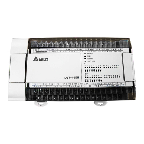
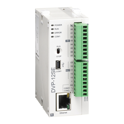
Delta DVP-20PM Instructions for use

www.deltaww.com
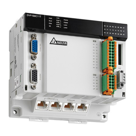
DVP-20PM
Application Manual
(Programming)
2014-02-12
Industrial Automation Headquarters
Delta Electronics, Inc.
Taoyuan Technology Center
No.18, Xinglong Rd., Taoyuan City,
Taoyuan County 33068, Taiwan
TEL: 886-3-362-6301 / FAX: 886-3-371-6301
Asia
Delta Electronics (Jiangsu) Ltd.
Wujiang Plant 3
1688 Jiangxing East Road,
Wujiang Economic Development Zone
Wujiang City, Jiang Su Province, P.R.C. 215200
TEL: 86-512-6340-3008 / FAX: 86-769-6340-7290
Delta Greentech (China) Co., Ltd.
238 Min-Xia Road, Pudong District,
ShangHai, P.R.C. 201209
TEL: 86-21-58635678 / FAX: 86-21-58630003
Delta Electronics (Japan), Inc.
Tokyo Ofce
2-1-14 Minato-ku Shibadaimon,
Tokyo 105-0012, Japan
TEL: 81-3-5733-1111 / FAX: 81-3-5733-1211
Delta Electronics (Korea), Inc.
1511, Byucksan Digital Valley 6-cha, Gasan-dong,
Geumcheon-gu, Seoul, Korea, 153-704
TEL: 82-2-515-5303 / FAX: 82-2-515-5302
Delta Electronics Int’l (S) Pte Ltd.
4 Kaki Bukit Ave 1, #05-05, Singapore 417939
TEL: 65-6747-5155 / FAX: 65-6744-9228
Delta Electronics (India) Pvt. Ltd.
Plot No 43 Sector 35, HSIIDC
Gurgaon, PIN 122001, Haryana, India
TEL : 91-124-4874900 / FAX : 91-124-4874945
Americas
Delta Products Corporation (USA)
Raleigh Ofce
P.O. Box 12173,5101 Davis Drive,
Research Triangle Park, NC 27709, U.S.A.
TEL: 1-919-767-3800 / FAX: 1-919-767-8080
Delta Greentech (Brasil) S.A.
Sao Paulo Ofce
Rua Itapeva, 26 - 3° andar Edicio Itapeva One-Bela Vista
01332-000-São Paulo-SP-Brazil
TEL: 55 11 3568-3855 / FAX: 55 11 3568-3865
Europe
Deltronics (The Netherlands) B.V.
Eindhoven Ofce
De Witbogt 20, 5652 AG Eindhoven, The Netherlands
TEL: 31-40-2592850 / FAX: 31-40-2592851
DVP-0099720-01
*We reserve the right to change the information in this manual without prior notice.
DVP-20PM Application Manual (Programming)

i
DVP-20PM Application Manual
Contents
Chapter 1 Program Framework of a DVP-PM Series Motion Controller
1.1 Structure of O100................................................................................................1-1
1.1.1 Manual Function of O100.............................................................................1-2
1.2 Structure of Ox Motion Subroutines.....................................................................1-3
1.3 Structure of P Subroutines...................................................................................1-4
1.4 Using O100, Ox Motion Subroutines, and P Subroutines....................................1-6
1.4.1 Structure of a Program.................................................................................1-6
Chapter 2 Hardware Specifications and Wiring
2.1 Hardware Specifications......................................................................................2-1
2.1.1 Specifications for Power...............................................................................2-1
2.1.2 Electrical Specifications for Input Terminals/Output Terminals......................2-1
2.1.3 Dimensions...................................................................................................2-4
2.2 Wiring..................................................................................................................2-6
2.2.1 Installation of a DVP-20PM Series Motion Controller in a Control Box.........2-7
2.2.2 Wiring Power Input.......................................................................................2-7
2.2.3 Safety Wiring................................................................................................2-8
2.2.4 Wiring Input/Output Terminals......................................................................2-8
2.2.5 Wiring a DVP-20PM Series Motion Controller and an Inferior Servo Drive 2-14
2.3 Communication Ports........................................................................................2-19
2.3.1 COM1 (RS-232 Port)..................................................................................2-19
2.3.2 COM2 (RS-485 Port)..................................................................................2-20
2.3.3 COM3 (RS-232/RS-485 Port).....................................................................2-20
Chapter 3 Devices
3.1 Device Lists.........................................................................................................3-1
3.2 Values, Constants, and Floating-point Numbers .................................................3-4
3.3 External Input Devices and External Output Devices..........................................3-6
3.4 Auxiliary Relays...................................................................................................3-8
3.5 Stepping Relays ..................................................................................................3-8
3.6 Timers .................................................................................................................3-8
3.7 Counters..............................................................................................................3-9
3.8 Registers ...........................................................................................................3-13
3.8.1 Data Registers............................................................................................3-13
3.8.2 Index Registers ..........................................................................................3-14
3.9 Pointers.............................................................................................................3-14

ii
3.10 Specail Auxiliary Relays and Special Data Registers........................................3-15
3.11 Functions of Special Auxiliary Relays and Special Data Registers ...................3-30
3.12 Special Data Registers for Motion Axes............................................................3-46
3.12.1 Descriptions of the Special Data Registers Related to Motion....................3-47
3.12.2 Introduction of Modes of Motion.................................................................3-64
3.12.3 Special Data Registers for Motion Axes .....................................................3-65
Chapter 4 Basic Instructions
4.1 Table of Basic Instructions ..................................................................................4-1
4.2 Descriptions of the Basic Instructions..................................................................4-3
Chapter 5 Applied Instructions and Basic Usage
5.1 Table of Applied Instructions ...............................................................................5-1
5.2 Structure of an Applied Instruction.......................................................................5-5
5.3 Processing Values...............................................................................................5-7
5.4 Using Index Registers to Modify Operands .......................................................5-10
5.5 Instruction Index................................................................................................5-10
5.6 Descriptions of the Applied Instructions.............................................................5-14
●(API 00~09) Loop control.............................................................................5-14
●(API 10~19) Transfer and comparison.........................................................5-23
●(API 20~29) Arithmetic.................................................................................5-36
●(API 30~39) Rotation and move ..................................................................5-48
●(API 40~49) Data processing ......................................................................5-59
●(API 50) High-speed processing..................................................................5-73
●(API 61~69) Convenience ...........................................................................5-74
●(API 78~87) I/O ...........................................................................................5-81
●(API 100~101) Communication ...................................................................5-86
●(API 110~175) Floating-point value .............................................................5-95
●(API 215~223) Logical operation...............................................................5-126
●(API 224~246) Comparison instructions....................................................5-129
●(API 147, 154, 202, 203, 256~260) Other instructions ..............................5-132
5.7 Motion Control Function Block Table ...............................................................5-145
5.8 Introduction of the Pins in a Motion Control Function Block ............................5-146
5.8.1 Definitions of Input Pins/Output Pins........................................................5-146
5.8.2 Timing Diagram for Input/Output Pins ......................................................5-148
5.8.3 Introducing the Use of PMSoft..................................................................5-148
5.9 Delta-defined Parameter Table........................................................................5-150
5.10 Uniaxial Motion Control Function Blocks.........................................................5-152
5.10.1 Absolute Single-speed Motion..................................................................5-152
5.10.2 Relative Single-speed Motion...................................................................5-156

iii
5.10.3 Absolute Two-speed Motion.....................................................................5-160
5.10.4 Relative Two-speed Motion......................................................................5-163
5.10.5 Inserting Single-speed Motion..................................................................5-166
5.10.6 Inserting Two-speed Motion .....................................................................5-170
5.10.7 JOG Motion..............................................................................................5-174
5.10.8 Manual Pulse Generator Mode.................................................................5-177
5.10.9 Electronic Gear Motion.............................................................................5-179
5.10.10 Returning Home.......................................................................................5-181
5.10.11 Setting Input Sources for Manual Pulse Generators/Electronic Gears.....5-183
5.10.12 Stopping Uniaxial Motion..........................................................................5-184
5.10.13 Parameter Setting I ..................................................................................5-186
5.10.14 Parameter Setting II .................................................................................5-188
5.10.15 Reading the Present Position/Speed of an Axis .......................................5-190
5.10.16 State of an Axis.........................................................................................5-192
5.10.17 Setting the Present Position of an Axis.....................................................5-194
5.10.18 Setting the Polarities of Input Terminals ...................................................5-195
5.10.19 Uniaxial Cyclic Electronic Cam Motion.....................................................5-197
5.10.20 Uniaxial Noncyclic Electronic Cam Motion ...............................................5-202
5.10.21 Multiaxial Cyclic Electronic Cam Motion...................................................5-206
5.10.22 Reading a Cam Point ...............................................................................5-210
5.10.23 Writing a Cam Point..................................................................................5-212
5.10.24 Calculating a Synchronization Ratio.........................................................5-214
5.10.25 Creating a Cam Curve..............................................................................5-217
5.10.26 Updating a Cam Curve.............................................................................5-224
5.10.27 Rotaty Cut ................................................................................................5-226
5.10.28 Flying Shear.............................................................................................5-232
5.10.29 Creating a Curve for a Wire Winding Machine .........................................5-239
5.11 Multiaxial Motion Control Function Blocks.......................................................5-243
5.11.1 Setting the Parameters of G-code Motion................................................5-243
5.11.2 Executing G-code Motion.........................................................................5-246
5.11.3 Stopping G-code Motion...........................................................................5-248
5.11.4 Reading an M-code..................................................................................5-250
5.12 Other Motion Control Function Blocks.............................................................5-252
5.12.1 High-speed Counter.................................................................................5-252
5.12.2 Setting High-speed Comparison...............................................................5-255
5.12.3 Resetting High-speed Comparison...........................................................5-257
5.12.4 Setting High-speed Capture.....................................................................5-260
5.12.5 High-speed Masking.................................................................................5-264
5.12.6 Setting an Interrupt...................................................................................5-266

iv
Chapter 6 Basic Usage of Motion Instructions and G-codes
6.1 Table of Motion Instructions and Table of G-codes..............................................6-1
6.2 Composition of a Motion Instruction/G-code........................................................6-3
6.2.1 Motion Instruction.........................................................................................6-3
6.2.2 G-code Instruction........................................................................................6-4
6.3 Descriptions of Motion Instructions......................................................................6-7
6.4 Descriptions of O Pointers/M-code Instructions.................................................6-40
6.5 Descriptions of G-code Instructions...................................................................6-45
Chapter 7 Using a DVP-20PM Series Motion Controller as a Slave
7.1 Access between DVP-EH2, DVP20PM (as a Master) and DVP-20PM (as a Slave)
............................................................................................................................7-1
7.1.1 Structure.......................................................................................................7-1
7.1.2 Example of Master-slave Data Exchange.....................................................7-1
Chapter 8 Application Examples
8.1 Drawing Paths by Motoin Instructions and G-codes............................................8-1
8.1.1 Paths............................................................................................................8-1
8.1.2 Steps ............................................................................................................8-2
8.2 Applying Application Examples in PMSoft...........................................................8-6
8.2.1 Program Structure........................................................................................8-6
8.2.2 Designing an Example Program...................................................................8-6
8.3 Planning Variable Speed Operation.....................................................................8-9
8.3.1 Program Structure........................................................................................8-9
8.3.1 Designing Programs.....................................................................................8-9
8.4 Connecting DVP20PM00D (as a Master) and DVP01PU-H2 (as a Slave) for
Controlling the Third Axis...................................................................................8-11
Chapter 9 Electronic Cam
9.1 Introduction of Electronic Cams...........................................................................9-1
9.2 Operation of an Electronic Cam ..........................................................................9-2
9.2.1 Initial Setting.................................................................................................9-2
9.2.1.1 Creating Electronic Cam Data...............................................................9-2
9.2.1.2 Setting Terminals...................................................................................9-2
9.2.1.3 Setting an Input/Output Pulse Type.......................................................9-3
9.2.1.4 Setting an Input/Output Ratio................................................................9-4
9.2.1.5 Setting a Starting Angle.........................................................................9-5
9.2.2 Setting a Master Axis....................................................................................9-6
9.2.3 Starting/Stopping an Electronic Cam..........................................................9-10
9.2.3.1 Starting/Stopping a Cyclic Electronic Cam ..........................................9-10

v
9.2.3.2 Starting/Stopping a Noncyclic Electronic Cam.....................................9-13
9.3 Registers for Electronic Cam Motion.................................................................9-15
9.4 Creating Electronic Cam Data...........................................................................9-19
9.4.1 Creating a Cam Chart in PMSoft................................................................9-20
9.4.1.1 Function Relating the Position of a Master Axis to the Position of a Slave
Axis .....................................................................................................9-20
9.4.1.2 Measuring the Relation between the Position of a Master Axis and the
Position of a Slave Axis at Work..........................................................9-23
9.4.2 Using DTO/DFROM to Create Electronic Cam Data..................................9-24
9.4.2.1 Creating/Modifying Electronic Cam Data.............................................9-30
9.4.2.2 Creating a Smooth Curve....................................................................9-32
9.4.2.3 Creating Rotary Cut Data....................................................................9-36
9.4.2.4 Electronic Cam Data for Cutting Thick Material...................................9-42
9.4.2.5 Offset Compensation for a Slave Error................................................9-46
9.4.2.6 Application of a Flying Shear—Checking the Position of a Cutter.......9-49
9.5 Multi-axis Cam...................................................................................................9-49
9.6 Practical Application of an Electronic Cam ........................................................9-53
9.6.1 Application of a Winfing Machine ...............................................................9-53
9.6.1.1 Operation of a High-speed Winding Device ........................................9-54
9.6.1.2 Wiring Hardware .................................................................................9-56
9.6.1.3 Creating an Electronic Cam Curve......................................................9-57
9.6.2 Application of a Rotary Cutter.....................................................................9-59
9.6.2.1 Operation of a Rotary Cutter...............................................................9-59
9.6.2.2 Creating an Electronic Cam Curve......................................................9-59
9.6.3 Application of a Flying Shear......................................................................9-61
9.6.3.1 Operation of a Rotary Cutter...............................................................9-61
9.6.3.2 Creating an Electronic Cam Curve......................................................9-62
Chapter 10 Application of G-codes
10.1 Downloading a Program with PEP.....................................................................10-1
10.2 Methods of Downloading G-codes.....................................................................10-2
10.2.1 PMGDL Software........................................................................................10-2
10.2.2 Coverting the G-codes in Data Registers...................................................10-8
10.3 Applying G-codes to a Dispenser....................................................................10-12
10.4 Storing G-codes/M-codes................................................................................10-17
Chapter 11 CANopen Communication Card
11.1 Introduction of DVP-FPMC: CANopen Communication Card............................11-1
11.2 Specifications ....................................................................................................11-1
11.3 Product Profile and Installation..........................................................................11-2

vi
11.4 Parameters for Control Registers......................................................................11-2
11.5 Descriptions of Control Registers......................................................................11-4
11.6 Setting a DVP-FPMC Mode.............................................................................11-19
11.7 Ethernet Mode of DVP-FPMC .........................................................................11-21
11.7.1 Communication between DVP-FPMC and an HMI...................................11-22
11.7.2 Communication between DVP-FPMC and PMSoft...................................11-24
11.8 LED Indicators and Troubleshooting ...............................................................11-27
Chapter 12 High-speed Comparison and High-speed Capture
12.1 High-speed Comparison and High-speed Capture............................................12-1
12.2 High-speed Comparison....................................................................................12-3
12.3 High-speed Capture ..........................................................................................12-6
Chapter 13 Appendix
13.1 Appendix A: Error Code Table...........................................................................13-1

vii

1Program Framework of a DVP-PM Series Motion Controller
Delta DVP-PM series motion controllers can put axes in particular positions at high-speeds, create linear
interpolations, and circular interpolations. They can execute basic instructions, applied instructions, motion
instructions, and G-codes. Different DVP-PM series motion controllers support different program
frameworks and functions. The functions that DVP-PM series motion controllers support are shown in the
table below. Function DVP-20PM DVP-10PM
Main program O100 ○○
Ox motion subroutines ○×
Program
P subroutines ○○
General instructions/Applied instructions ○○
Motion instructions ○×
G-codes ○×
Instruction
M-codes ○×
JOG motion ○○
Returning home ○○
Variable motion ○○
Single-speed motion ○○
Inserting single-speed motion ○○
Two-speed motion ○○
Inserting two-speed motion ○○
Triggering single-speed motion by means
of an external signal ○×
Manual pulse generator mode ○○
Uniaxial motion
Cyclic/Noncyclic electronic cam motion ○×
In this chapter, the basic program frameworks of DVP-PM series motion controllers are described. Owing
to the fact that the functionality of a DVP-PM series motion controller is composed of sequence control and
positioning control, a program comprises O100, Ox motion subroutines, and P subroutines. O100, Ox
motion subroutines, and P subroutines are described in this chapter. Basic instructions, applied
instructions, motion instructions, and G-codes will be introduced in other chapter 4~chapter 6. The
specifications for DVP-PM series motion controllers are shown in the table below.
Specifications DVP-10PM DVP-20PM
High-speed output 4 axes (1000 kHz) 3 axes (500 kHz)
PWM Precision: 0.3%@200 kHz -
High-speed counter
6 input terminals (2 differential
input terminals, and 4 input
terminals whose collectors are
open collectors)
2 input terminals
Program capacity 64K steps 64K steps
Execution speed
LD: 0.14 us
MOV: 2 us
DMUL: 7.6 us
DEMUL: 6.1 us
-
1.1 Structure of O100
O100 is a sequence control program. It is the main program in a DVP-PM series motion controller. It only
supports basic instructions and applied instructions. Users can use these two types of instructions to
process I/O data, call P subroutines, and enable Ox motion subroutines (Ox0~Ox99). O100 functions as a
main program. Motion subroutines are enabled through O100. There is hierarchical relation between O100
and motion subroutines. The characteristics of O100 are described below.
1. There are two methods of enabling O100.
If the STOP/RUN switch of a DVP-PM series motion controller is turned from the “STOP” position to
the “RUN” position when the DVP-PM series motion controller is powered, M1072 will be ON, and
O100 will run.
DVP-20PM Application Manual 1-1

1Program Framework of a DVP-PM Series Motion Controller
If a DVP-PM series motion controller is powered, users can use communication to set M1072 to ON,
and to run O100.
Communication
STOP/RUN switch
M1072 O100
runs.
2. O100 is scanned cyclically. The scan of the main program O100 starts from the starting flag O100. After
the ending instruction M102 is scanned, the scan of the main program O100 will go back to the starting
flag O100.
O100
M102
.
.
.
The main program starts.
The main program ends.
The sequence control
program is scanned cyclically.
Main Program
3. There are three methods of disabling O100.
If the STOP/RUN switch of a DVP-PM series motion controller is turned form the “RUN” position to
the “STOP” position when the DVP-PM series motion controller is powered, M1072 will be OFF,
and O100 will stop. If O100 stops, Ox motion subroutines and P subroutines will not be executed.
If a DVP-PM series motion controller is powered, users can use communication to set M1072 to
OFF, and to stop O100. If O100 stops, Ox motion subroutines and P subroutines will not be
executed.
If an error occurs when O100 is compiled or when O100 runs, O100 will stop automatically. Please
refer to appendix A in chapter 15 for more information about error codes.
4. O100 supports basic instructions and applied instructions. Users can write a control program according
to their needs. They can set the parameters of motion instructions, and motion subroutine numbers
(Ox0~Ox99) in O100.
O100 does not support motion instructions and G-codes. Motion instructions and G-codes must be
used in the motion subroutines Ox0~Ox99. Please refer to section 1.2 for more information.
O100 can call P subroutines. Please refer to section 1.3 for more information.
5. The description of O100 is shown below.
O100 Description
Enabling
O100 Starting flag O100 (If O100 is a ladder diagram in PMSoft, the starting flag in O100 will be
set automatically, and users do not have to write the starting flag.)
Disabling
O100 Ending instruction M102 (If O100 is a ladder diagram in PMSoft, the ending instruction
M102 will be set automatically, and users do not have to write the ending instruction M102.)
Executing
O100
1. The STOP/RUN switch of a DVP-PM series motion controller is turned form the “STOP”
position to the “RUN” position.
2. Users use communication to set M1072 to ON.
Operation
characteristic O100 is scanned cyclically.
Instructions
supported Basic instructions and applied instructions are supported.
Number There is only one O100 in a program.
Characteristic
and function
1. It is a sequence control program.
2. It can enable the motion subroutines Ox0~Ox99, and call P subroutines.
3. If O100 is used with Ox motion subroutines and P subroutines, O100, the Ox motion
subroutines, and the P subroutines can be arranged in any order.
1.1.1 Manual Function of O100
Users can set manual motion modes by means of special registers in O100. (Please refer to section 3.12
for more information.)
DVP-20PM Application Manual
1-2

1Program Framework of a DVP-PM Series Motion Controller
1.2 Structure of Ox Motion Subroutines
The motion subroutines Ox0~Ox99 are motion control programs. They are subroutines which control the
motion of the axes of a DVP-PM series motion controller. Ox0~Ox99 support basic instructions, applied
instructions, motion instructions, and G-codes. They can call P subroutines. Users can control the paths of
the axes of a DVP-PM series motion controller through Ox motion subroutines. The characteristics of Ox
motion subroutines are described below.
1. There are two methods of enabling an Ox motion subroutine.
When O100 runs, users can set motion subroutine numbers in O100. (The motion subroutine
numbers must be in the range of Ox0 to Ox99. The users can set a motion subroutine number in
O100 by setting D1868. The value in D1868 must be in the range of H8000 to H8063.) If the users
want to enable an Ox motion subroutine, they have to set M1074 to ON or set bit 12 in D1846 to
ON.
Before an Ox motion subroutine is enabled, users have to make sure that no Ox motion subroutine
runs.
Oxn
(Motionsubroutinenumber)
O100 runs. M1074 is set to ON,
orbit 12 in D1846
is set to ON.
Oxn
runs.
2. Whenever an Ox motion subroutine is enabled, it is executed once.After O100 enables an Ox motion
subroutine, the execution of the Ox motion subroutine will start from the starting flag in the Ox motion
subroutine. After the ending instruction M2 in the Ox motion subroutine is executed, the execution of
the Ox motion subroutine will stop.
MOV
.
.
.
.
.
.
.
.
.
H800A D1868
OUT M1074
X0
.
.
.
MOVP K100 D1836
MOVP K100 D1837
MOV H1000 D1846 or
Setting the OxnumberOx10, and setting bit 15 to ON.
If X0is ON, the motion subroutine Ox10 will be enabled.
Cyclic scan
It is executed once.
X0isON.
Ox10
Motionsubroutine
O100
Main program
If X0 is ON, the motion subroutine Ox10 will be enabled. After the ending instruction M2 in Ox10 is
executed, the execution of Ox10 will stop. (Ox10 is executed once. If Ox10 needs to be executed again,
X0 has to be set to ON.)
3. There are four methods of disabling an Ox motion subroutine.
If the STOP/RUN switch of a DVP-PM series motion controller is turned form the “RUN” position to
the “STOP” position when the DVP-PM series motion controller is powered, M1072 will be OFF,
O100 will stop, and Ox motion subroutines will not be executed.
Users can stop the execution of Ox motion subroutines by means of the external terminal Stop0.
If a DVP-PM series motion controller is powered, users can use communication to set the value in
D1846 to 0, or to set M1074 to OFF, and to stop the execution of Ox motion subroutines.
If an error occurs when an Ox motion subroutine is compiled or when an Ox motion subroutine is
DVP-20PM Application Manual 1-3

1Program Framework of a DVP-PM Series Motion Controller
executed, the execution of the Ox motion subroutine will stop automatically. Please refer to
appendix A in chapter 15 for more information about error codes.
4. An Ox motion subroutine supports basic instructions, applied instructions, motion instructions, and
G-codes. Users can write a motion program according to their needs. They can control the motion of
the axes of a DVP-PM series motion controller by setting the parameters of the axes.
Basic instructions, applied instructions, motion instructions and G-codes must be used in the
motion subroutines Ox0~Ox99.
Ox motion subroutines can call P subroutines. Please refer to section 1.3 for more information.
5. The description of Ox motion subroutines is shown below.
Ox motion
subroutine Description
Enabling an
Ox motion
subroutine
There are 100 Ox motion subroutines (Ox0~Ox99).
(If an Ox motion subroutine is a ladder diagram in PMSoft, the starting flag in the Ox motion
subroutine will be set automatically, and users do not have to write the starting flag.)
Disabling an
Ox motion
subroutine
Ending instruction M2 (If an Ox motion subroutine is a ladder diagram in PMSoft, the ending
instruction M2 will be set automatically, and users do not have to write the ending
instruction M2.)
Executing an
Ox motion
subroutine
1. If users set bit 12 in D1846 or M1074 to ON when O100 runs, an Ox motion subroutine
will be enabled.
2. If users use communication to set bit 12 in D1846 or M1074 to ON when O100 runs, an
Ox motion subroutine will be enabled.
3. Users can stop the execution of Ox motion subroutines by means of the external
terminal Stop0.
Note: Before an Ox motion subroutine is enabled, users have to make sure that no Ox
motion subroutine runs.
Operation
characteristic Whenever an Ox motion subroutine is enabled, it is executed once. If an Ox motion
subroutine needs to be executed again, it has to be enabled again.
Instructions
supported Basic instructions, applied instructions, motion instructions, and G-codes are supported.
Note: Users have to avoid using pulse instructions.
Number There are 100 Ox motion subroutines in a program. If users want to enable a motion
subroutine number, they have to set D1868, and set bit 12 in D1846 or M1074 to ON.
Characteristic
and function
1. Ox0~Ox99 are motion subroutines. (They can only be enabled by O100.)
2. Ox motion subroutines can be used to control the third axis (the Z-axis). Please refer to
section 6.4 for more information about G00 and G01.
3. An Ox motion subroutine can be enabled/disabled by an external terminal, a program, or
communication.
4. Ox motion subroutines can call P subroutines.
5. If Ox motion subroutines are used with O100 and P subroutines, the Ox motion
subroutines, O100, and the P subroutines can be arranged in any order.
1.3 Structure of P Subroutines
P subroutines are general subroutines. They can be called by O100 and Ox motion subroutines. If P
subroutines are called by O100, the P subroutines will support basic instructions and applied instructions. If
P subroutines are called by Ox0~Ox99, the P subroutines will support basic instructions, applied
instructions, motion instructions, and G-codes. After O100 or an Ox motion subroutine calls a P subroutine,
the P subroutine will be executed. After SRET in the P subroutine is executed, the lines under the
instruction which calls the P subroutine will be executed.
1. There are two methods of enabling a P subroutine.
O100 can call P subroutines.
Ox motion subroutines can call P subroutines.
2. Whenever a P subroutine is called, it is executed once. After O100 or an Ox motion subroutine calls a P
subroutine, the P subroutine will be executed. After the ending instruction SRET in the P subroutine is
executed, the execution of the P subroutine will stop, and the lines under the instruction which calls the
P subroutine will be executed.
DVP-20PM Application Manual
1-4

1Program Framework of a DVP-PM Series Motion Controller
MOV
CALL
.
.
.
.
.
.
H800A D1868
OUT M1074
X0
.
.
.
.
.
P0
P2
CALL
b
a
M1000
M1000
Subroutine
section
MOVP K100 D1836
ABST
DRV X-20000 Y20000
MOVP D1837
K100
.
.
.
.
O100
Mainprogram
Cyclic scan
O100 and Ox10
diverge. Calling P0
Setting the motion subroutine number Ox10
If X0 is ON, Ox10 will be enabled.
The path a is valid.
Ox10isexecutedonce.
OX10
Motion subroutine
Ox10isexecutedonce.
Calling P2
P2
subroutine
P2isexecutedonce.
P2isexecutedonce.
P0
subroutine
The subroutine P0 supports basic instructions and applied instructions. The subroutine P2
supports basic instructions, applied instructions, motion instructions, and G-codes.
3. There are three methods of disabling a P subroutine.
If the STOP/RUN switch of a DVP-PM series motion controller is turned form the “RUN” position to
the “STOP” position when the DVP-PM series motion controller is powered, M1072 will be OFF,
O100 will stop, and Ox motion subroutines and P subroutines will not be executed.
If a DVP-PM series motion controller is powered, users can use communication to set the value in
D1846 to 0, or to set M1074 to OFF, to stop the execution of Ox motion subroutines, and to stop the
execution of P subroutines.
If an error occurs when a P subroutine is executed, the execution of the P subroutine will stop
automatically. Please refer to appendix A in chapter 15 for more information about error codes.
4. If P subroutines are called by O100, the P subroutines will support basic instructions and applied
instructions. If P subroutines are called by Ox0~Ox99, the P subroutines will support basic instructions,
applied instructions, motion instructions, and G-codes.
5. The description of P subroutines is shown below.
P subroutine Description
Enabling a P
subroutine
There are 256 P subroutines (P0~P255).
(If a P subroutine is a ladder diagram in PMSoft, the starting flag in the P subroutine
will be set automatically, and users do not have to write the starting flag.)
Disabling a P
subroutine
Ending instruction SRET (If a P subroutine is a ladder diagram in PMSoft, the ending
instruction SRET will be set automatically, and users do not have to write the ending
instruction SRET.)
DVP-20PM Application Manual 1-5

1Program Framework of a DVP-PM Series Motion Controller
DVP-20PM Application Manual
1-6
P subroutine Description
Executing a P
subroutine 1. O100 can call P subroutines.
2. Ox motion subroutines can call P subroutines.
Operation
characteristic Whenever a P subroutine is enabled, it is executed once. If a Pn subroutine needs to
be executed again, it has to be enabled again.
Instruction
supported
1. If P subroutines are called by O100, the P subroutines will support basic
instructions and applied instructions.
2. If P subroutines are called by Ox motion subroutines, the P subroutines will
support basic instructions, applied instructions, motion instructions, and G-codes.
Note: If P subroutines are called by Ox motion subroutines, users have to avoid using
pulse instructions.
Number There are 256 P subroutines in a program.
Characteristic
and function
1. P subroutines are general subroutines.
2. P subroutines can be called by O100 and Ox motion subroutines.
3. If P subroutines are used with O100 and Ox motion subroutines, the P
subroutines, O100, and the Ox motion subroutines can be arranged in any order.
1.4 Using O100, Ox Motion Subroutines, and P Subroutines
O100, Ox motion subroutines, and P subroutines are introduced in section 1.1~section 1.3. In this section,
a program composed of O100, Ox motion subroutines, and P subroutines is described.
1.4.1 Structure of a Program
Suppose a program is composed of O100, Ox0, Ox3, P1, and P2. The five program blocks are shown
below.
Mainprogram
O100
M102
.
.
.
.
.
.
.
.
.
.
.
.
.
Calling Ox0
Calling P2
Motion subroutine
Ox0
Calling P1
.
.
.
.
.
M2
Subroutine
P2
Calling Ox3
.
.
.
.
.
SRET
Motion subroutine
Ox3
.
.
M2
Subroutine
P1
.
.
SRET

1Program Framework of a DVP-PM Series Motion Controller
In order to describe the program, the program is divided into 5 sections (section (1)~section (5)).
.
.
.
.
.
.
.
.
(1)
(3)
(2)
(5)
.
.
.
.
.
.
.
.(4)
.
.
.
.
.
.
.
M1000 CALL P1
MOV H8000 D1868
SET M1074
CALL P2
M1000
BRET
DMOV
MOV H8003 D1868
M1074
SET
K0 D1848
M1000
.
.
Ox0
Motion subroutine
Calling P1
O100
Main program
Setting the motionsubroutine number Ox0
Enabling Ox0
Calling P2
P1
Subroutine Ox3
Motion subroutine P2
Subroutine
Setting the motion subroutine number Ox3
Enabling Ox3
The program is described below.
1. Section (1)~section (5) are created in numerical order, but they can be arranged in any order.
2. There is only one O100. O100 can not be called by another program, but it can freely call Ox motion
subroutines and P subroutines.
3. Ox motion subroutines can be called by O100 and P subroutines, and it can call P subroutines.
4. P subroutines can be called by O100 and Ox motion subroutines, and it can call Ox motion
subroutines.
Note:
1. One Ox motion subroutine is executed at a time. If Ox0 is executed, Ox3 can not be executed. If Ox3 is
executed, Ox0 can not be executed.
2. After O100 or a P subroutine enables an Ox motion subroutine, the next line will be executed, and the
execution of the Ox motion subroutine will be ignored.
DVP-20PM Application Manual 1-7

1Program Framework of a DVP-PM Series Motion Controller
DVP-20PM Application Manual
1-8
3. Whenever an Ox motion subroutine is enabled, it is executed once. If an Ox motion subroutine needs
to be executed again, it has to be enabled again.
The instructions supported by O100, Ox0, Ox3, P1 and P3 are described below. (O: Supported; X: Not
supported)
Section O100 Ox0 and Ox3 P1 P2
Basic
instruction O O O O
Applied
instruction O O O O
Motion
instruction X O O X
G-code X O O X
Description - -
P1 is called by Ox0,
and therefore it
supports motion
instructions and
G-codes.
P2 is called by O100,
and therefore it does
not support motion
instructions and
G-codes.
Additional remark:
Main program Subroutine Motion subroutine
Order In any order In any order In any order
Execution It runs normally. P subroutines can be called
by O100 or Ox motion
subroutines.
Ox motion subroutines can
be called by O100 or P
subroutines.
Operation It is scanned cyclically. Whenever a subroutine is
called, it is executed once.
Whenever a motion
subroutine is called, it is
executed once.
Number 1 main program 256 subroutines
They can be used
according to users’ needs.
100 motion subroutines
They can be used
according to users’ needs.

2Hardware Specifications and Wiring
DVP-20PM Application Manual 2-1
2.1 Hardware Specifications
Electrical specifications and wiring are described in this chapter. Please refer to chapter 5~chapter 6 for
more information about the writing of a program and the use of instructions. For more information about the
peripherals purchased, please refer to the manuals attached to them.
2.1.1 Specifications for Power
Item 20PM
Supply voltage 100~240 V AC (-15%~10%), 50/60 Hz5%
Fuse 2 A/250 V AC
Power
Consumption 60 VA
24 V DC power 500 mA
Power protection 24 V DC output is equipped with a short circuit protection.
Surge voltage
withstand level 1500 V AC (Primary-secondary), 1500 V AC (Primary-PE), 500 V AC (Secondary-PE)
Insulation
impedance Above 5 MΩ
(The voltage between all input terminals/output terminals and the ground is 500 V DC.)
Noise immunity ESD: 8 kV air discharge
EFT: Power line: 2 kV; digital I/O: 1 kV; analog & communication I/O: 250 V
Ground The diameter of the ground should not be less than the diameters of the cables connected
to the terminals L and N. (If several DVP-20PM series motion controllers are used, please
use single-point ground.)
Operation/Storage Operation:0°C~55°C (Temperature), 5~95% (Humidity), pollution degree 2
Storage: -25°C ~70°C (Temperature), 5~95% (Humidity)
Vibration/Shock
resistance International standards IEC 61131-2, IEC 68-2-6 (TEST Fc)/IEC 61131-2 & IEC 68-2-27
(TEST Ea)
Weight Approximately 478/688 g
2.1.2 Electrical Specifications for Input Terminals/Output Terminals
Electrical specifications for input terminals:
DVP20PM00D Maximum input
Terminal Description Response Current Voltage
START0 and
START1 Input terminals for starting DVP20PM00D 10 ms 6 mA 24 V
STOP0 and
STOP1 Input terminals for stopping DVP20PM00D 10 ms 6 mA 24 V
LSP0/LSN0 and
LSP1/LSN1 Positive limit switches/Left limit switches (for the
X-axis and the Y-axis) 10 ms 6 mA 24 V
A0+, A0-, A1+,
and A1- A-phase input terminals for manual pulse
generators (differential input terminals) 200 kHz 15 mA 5~24 V
B0+, B0-, B1+,
and B1- B-phase input terminals for manual pulse
generators (differential input terminals) 200 kHz 15 mA 5~24 V
PG0+, PG0-,
PG1+, and PG1- PG signals (differential input terminals) 200 kHz 15 mA 5~24 V
DOG0 and DOG1
The use of the input terminals varies with the
mode used.
1. DOG signals for returning home
2. Signals for starting the insertion of
single-speed motion or the insertion of
two-speed motion
1 ms 6 mA 24 V
X0~X7 General input terminals 200 kHz 15 mA 24 V

2Hardware Specifications and Wiring
DVP-20PM Application Manual
2-2
DVP20PM00M Maximum input
Terminal Description Response Current Voltage
START0 and
START1 Input terminals for starting DVP20PM00M 10 ms 6 mA 24 V
STOP0 and STOP1 Input terminals for stopping DVP20PM00M 10 ms 6 mA 24 V
LSP0/LSN0 and
LSP1/LSN1 Positive limit switches/Left limit switches (for the
X-axis and the Y-axis) 10 ms 6 mA 24 V
X1/X2 Positive limit switch/Left limit switch
(common-point ground) (for the Z-axis) 10 ms 6 mA 24 V
A0+, A0-, A1+, and
A1-
A-phase input terminals for manual pulse
generators (differential input terminals)
(A1+ and A1- are for the Y-axis and the Z-axis.) 200 kHz 15 mA 5~24 V
B0+, B0-, B1+, and
B1-
B-phase input terminals for manual pulse
generators (differential input terminals)
(B1+ and B1- are for the Y-axis and Z-axis.) 200 kHz 15 mA 5~24 V
PG0+, PG0-,
PG1+, and PG1- PG signals (differential input terminals) 200 kHz 15 mA 5~24 V
X3 PG signal (common-point ground) (for the Z-axis) 10 ms 6 mA 24 V
DOG0 and DOG1
The use of the input terminals varies with the
mode used.
1. DOG signals for returning home
2. Signals for starting the insertion of
single-speed motion or the insertion of
two-speed motion
1 ms 6 mA 24 V
X0
The use of the input terminal varies with the
mode used.
1. DOG signal for returning home
(common-point ground) (for the Z-axis)
2. Signal for starting the insertion of
single-speed motion or the insertion of
two-speed motion (common-point ground)
(for the Z-axis)
10 ms 6 mA 24 V
X4~X7 General input terminals 200 kHz 15 mA 24 V
Electrical specifications for output terminals:
DVP20PM00D
Terminal Description Response Maximum
current output
CLR0+, CLR0-,
CLR1+, and CLR1-
CLR signals (for clearing the present positions of
servo drives which are stored in registers in the
servo drives) 10 ms 20 mA
FP0+, FP0-, FP1+,
and FP1-
U/D: Counting up
P/D: Pulse
A/B: A phase 500 kHz 40 mA
RP0+, RP0-, RP1+,
and RP1-
U/D: Counting down
P/D: Direction
A/B: B phase 500 kHz 40 mA
Y0~Y7 General output terminals 200 kHz 40 mA
DVP20PM00M
Terminal Description Response Maximum
current output
CLR0+, CLR0-,
CLR1+, and CLR1-
CLR signals (for clearing the present positions of
servo drives which are stored in registers in the
servo drives) 10 ms 20 mA
Y2 CLR signal (for the Z-axis) 10 ms 30 mA

2Hardware Specifications and Wiring
DVP-20PM Application Manual 2-3
Terminal Description Response Maximum
current output
FP0+, FP0-, FP1+,
FP1-, FP2+, and
FP2-
U/D: Counting up
P/D: Pulse
A/B: A phase 500 kHz 40 mA
RP0+, RP0-, RP1+,
RP1-, RP2+, and
RP2-
U/D: Counting down
P/D: Direction
A/B: B phase 500 kHz 40 mA
Y3~Y7 General output terminals 200 kHz 40 mA
Digital input terminals:
DVP-20PM series motion controller
24 V DC common terminalItem
Specifications Low speed High speed of 200 kHz#1 Remark
Wiring type A current flows into the terminal S/S (sinking), or a
current flows from the terminal S/S.
Input indicator
LED indicator (If the LED indicator corresponding to an
input terminal is ON, the input terminal is ON. If the
LED indicator corresponding to an input terminal is
OFF, the input terminal is OFF.)
Input voltage -
OffOn 20 us
Action
level OnOff 30 us
Response time/Noise
reduction#2 10 ms/0.5 us
0.5us
#1: The input terminalsA0+,
A0-, A1+, A1-, B0+, B0-,
B1+, B1-, PG0+, PG0-,
PG1+, and PG1- are
high-speed input terminals,
and the other input
terminals are low-speed
input terminals.
#2: Users can filter pulses by
setting the input terminals
X0~X7 to ON after the
pulses in 10 ms~60 ms are
received.
Digital output terminals:
DVP-20PM series motion controller
Transistor output terminal
connected to a common terminal#1
Item
Specifications Low speed High speed
Relay output terminal connected to a
common terminal#1
Maximum frequency of
output signals 10 kHz 200 kHz 100 Hz
Output indicator LED indicator (If the LED indicator corresponding to an output terminal is ON, the
output terminal is ON. If the LED indicator corresponding to an output terminal is
OFF, the output terminal is OFF.)
Minimum load - 2 mA/DC power
Working voltage 5~30 V DC <250 VAC, 30 V DC
Isolation Optocoupler Electromagnetic isolation
Resistance 0.5A/output terminal (2A/COM) 2 A/ output terminal (5 A/COM)
Inductance 9 W (24 V DC) #2
Current
specifications Bulb 2 W (24 V DC) 20 W DC/100 WAC
OffOn 20 us
Response
time OnOff 30 us 0.2 us 10 ms
Overcurrent protection N/A
#1: Y0~Y7 on DVP20PM00D are relay output terminals. FP2+ and FP2- on DVP20PM00M are high-speed transistor
output terminals, Y2 and T3 on DVP20PM00M are low-speed transistor output terminals, and Y4~Y7 on
DVP20PM00M are relay output terminals. Y0 is connected to the common terminal C0, Y1 is connected to the
common terminal C1, Y2 and Y3 are connected to the common terminal C2, and Y4~Y7 are connected to the
common terminal C3.

2Hardware Specifications and Wiring
DVP-20PM Application Manual
2-4
#2: Life cycle curve
Contact
Current(A)
20
0.
5
0.1 0.
2
30
50
0.3 0.
7
12
200
300
500
100
1000
2000
3000
Operation(X10)
3
120VAC Resistive
30VDC Inductive(t=7ms)
240VACInductive(cos 0.4)
ψ
=
120VAC Inductive(cos =0.4)
ψ
100~200VDC
Inductive(t=7~40ms)
30VDC
Inductive
(t=40ms)
2.1.3 Dimensions
174
164
80
82.2
90
(Unit: mm)
Other manuals for DVP-20PM
1
Table of contents
Other Delta Controllers manuals

Delta
Delta DZNT-104T User manual

Delta
Delta VFD-007B User manual

Delta
Delta VFD-B Series User manual

Delta
Delta DVP-EH2 Series User manual

Delta
Delta AH500 series User manual

Delta
Delta 2SP2 User manual

Delta
Delta DTV Series User manual

Delta
Delta VFD-L User manual

Delta
Delta DVP-ES2 User manual

Delta
Delta DAC-633 User manual

Delta
Delta NC10EB User manual

Delta
Delta 29FWC-100E User manual

Delta
Delta AH05PM-5A User manual

Delta
Delta DCS User manual

Delta
Delta DVP-PM Series Instructions for use

Delta
Delta VFD-V Series User manual

Delta
Delta DVP-SX2 User manual

Delta
Delta VFD7A5MS23ANSHA User manual
Delta
Delta DAC-1600 User manual

Delta
Delta DVP-ES2 User manual