Elster Instromet EnCal 3000 Quad User manual

___________________________________________________________________________________________________________
EnCal 3000 Quad –Hardware Manual 22/06/2017
EnCal 3000 Quad
Gas Chromatograph
Hardware Manual
73022350 g 22.06.2017

Elster GmbH
___________________________________________________________________________________________________________
EnCal 3000 Quad–Hardware Manual 22/06/2017
2/52
Contact Information...................................................................................................................................... 3
Safety Information ........................................................................................................................................... 4
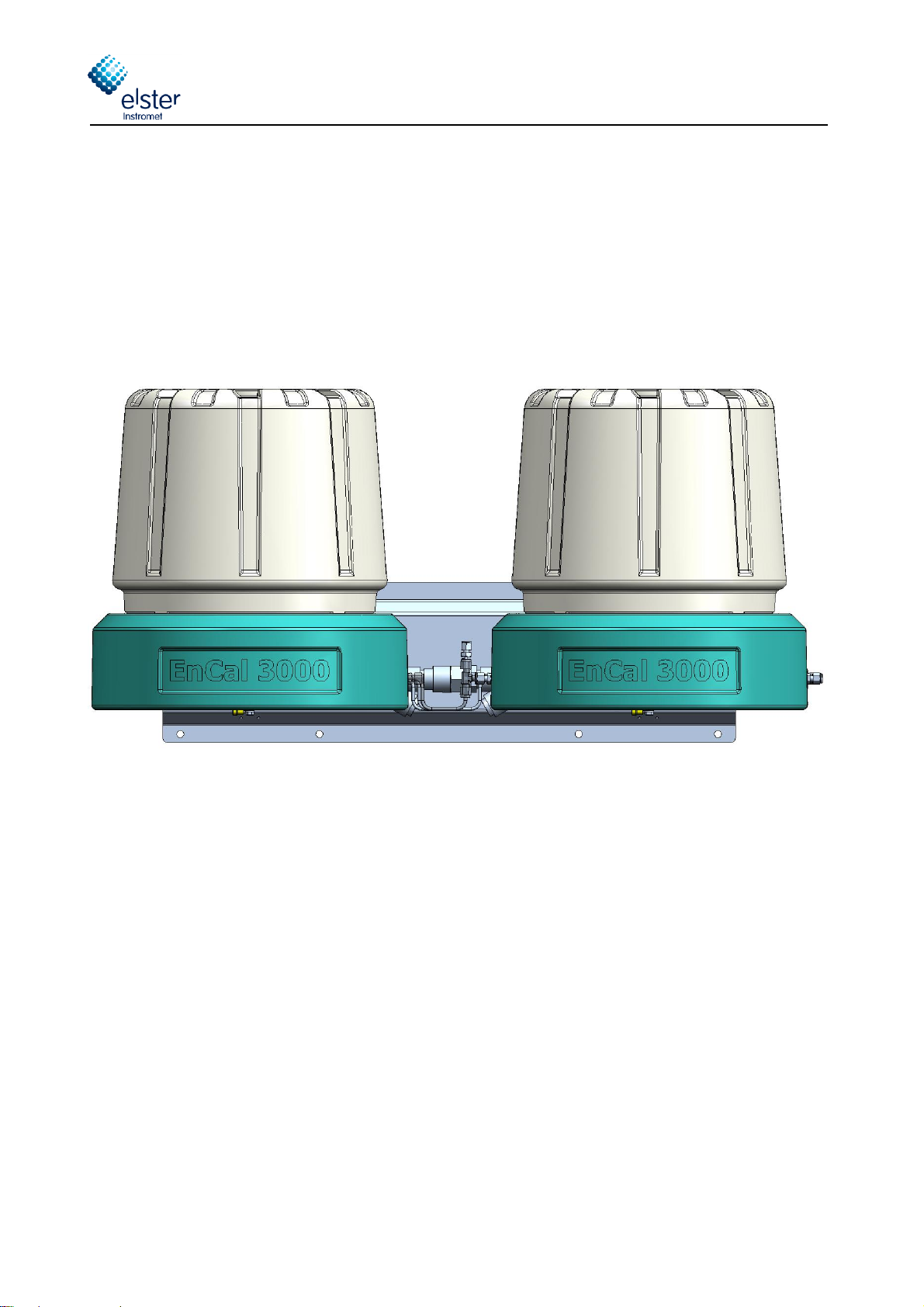
Gas quality measurement system EnCal 3000 Quad................................................................................... 5
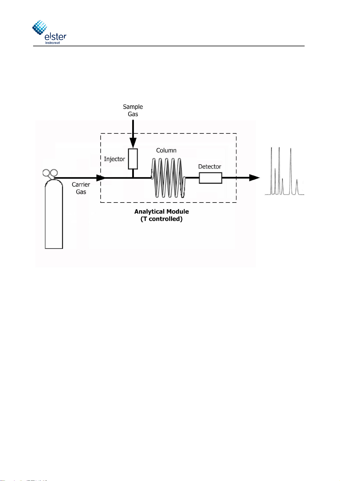
1Process Gas Chromatography –General Introduction....................................................................... 7
1.1 Analytical Principle................................................................................................................................7
1.1.1 Column .................................................................................................................................8
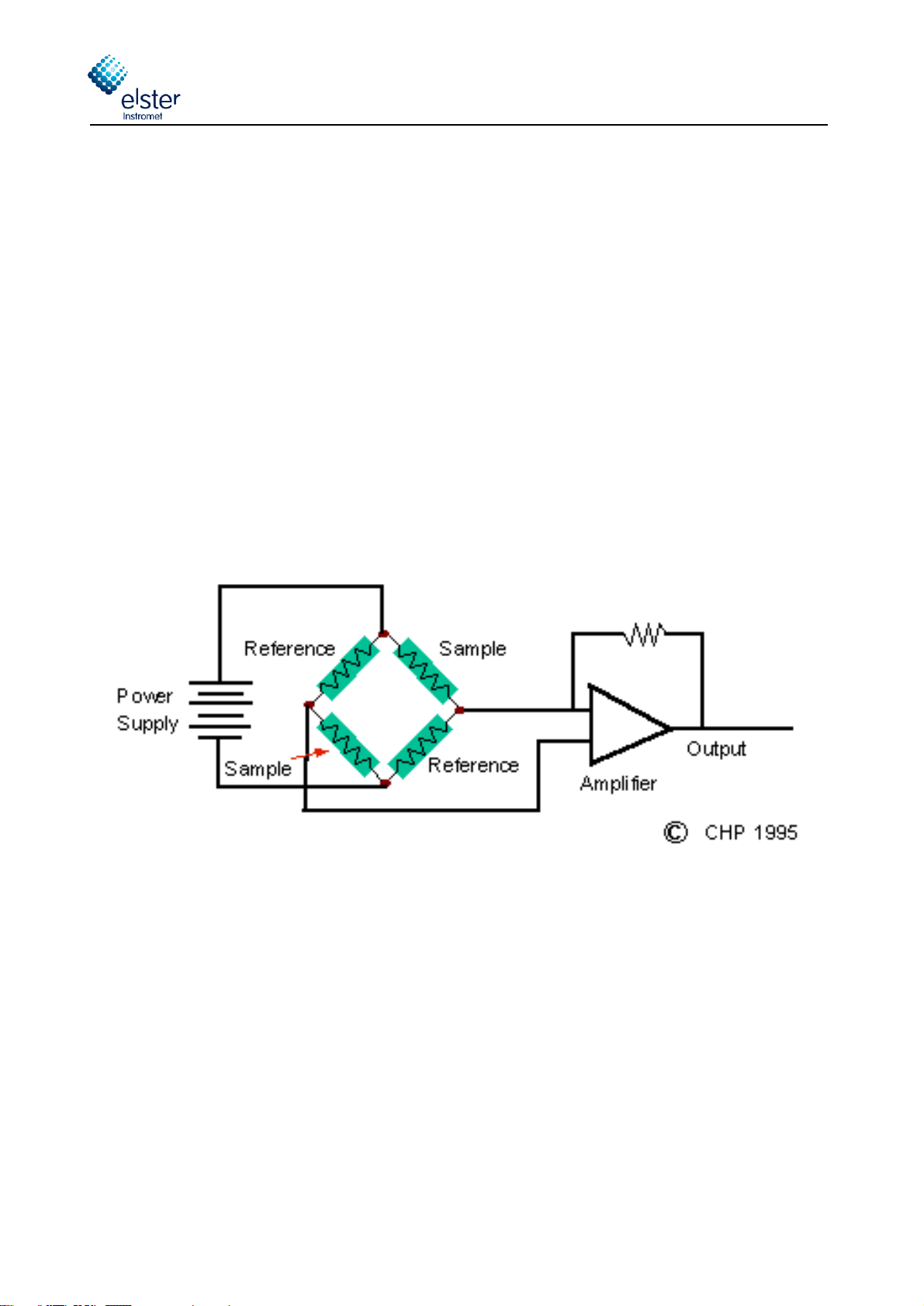
1.1.2 Detector................................................................................................................................9
1.1.3 Sample Injector ...................................................................................................................10
1.2 Process Gas Chromatography ..............................................................................................................11
2Functional Design ................................................................................................................................. 12
2.1 Introduction .......................................................................................................................................12
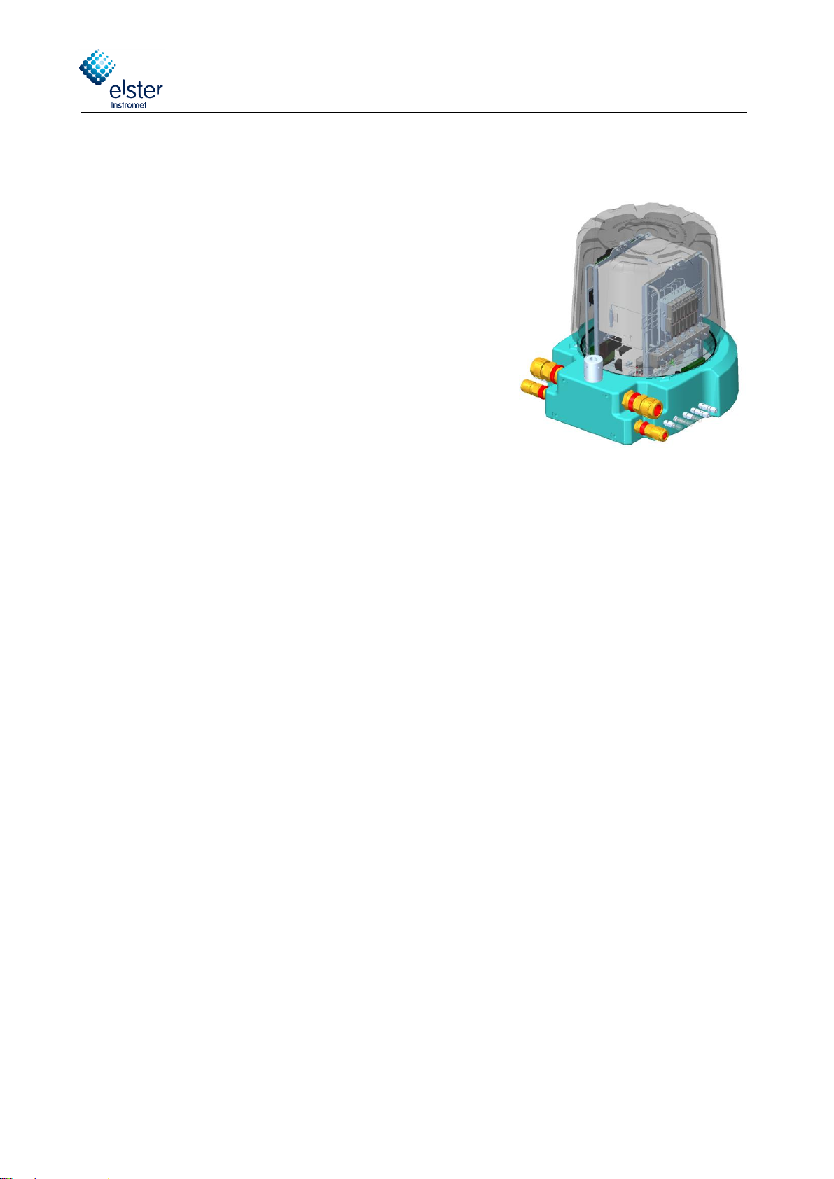
2.2 Enclosure...........................................................................................................................................13
2.3 Assembly of major components and internal components.......................................................................14
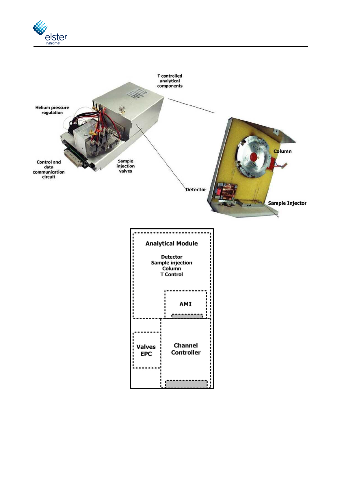
2.4 Channel .............................................................................................................................................15
2.5 Processor Board .................................................................................................................................19
2.6 Interconnection Board.........................................................................................................................22
2.7 Electrical connection ...........................................................................................................................23
2.8 Cabinet Heaters..................................................................................................................................24
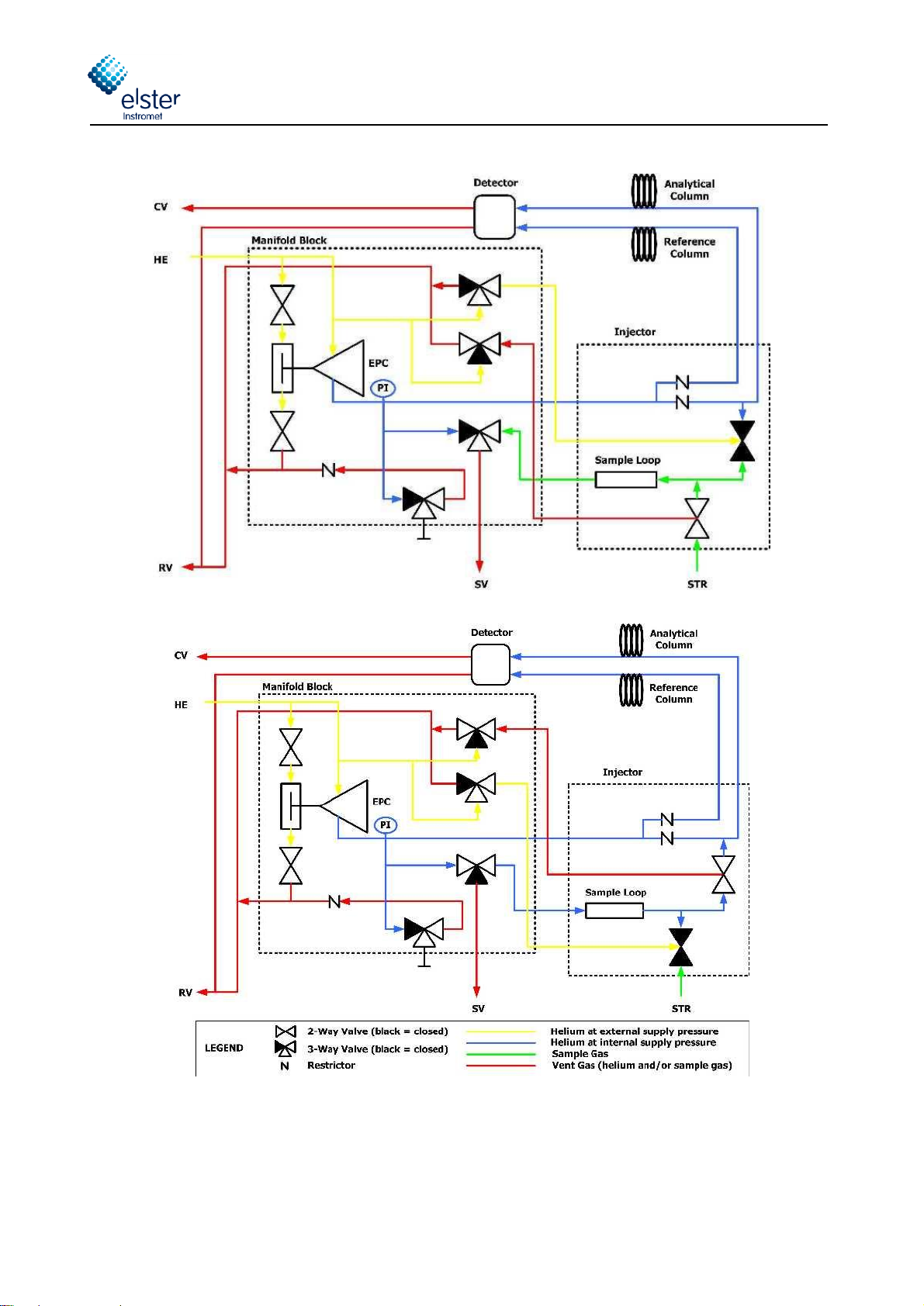
2.9 Internal sample system .......................................................................................................................25
2.9.1 Double Block and Bleed Function ...........................................................................................27
2.9.2 Internal Sample Bypass ........................................................................................................27
2.10 Gas Connections.................................................................................................................................28
2.11 Breather ............................................................................................................................................29
2.12 Cable Glands ......................................................................................................................................30
2.13 External Switch ..................................................................................................................................30
3Technical Specifications ..................................................................................................................... 31
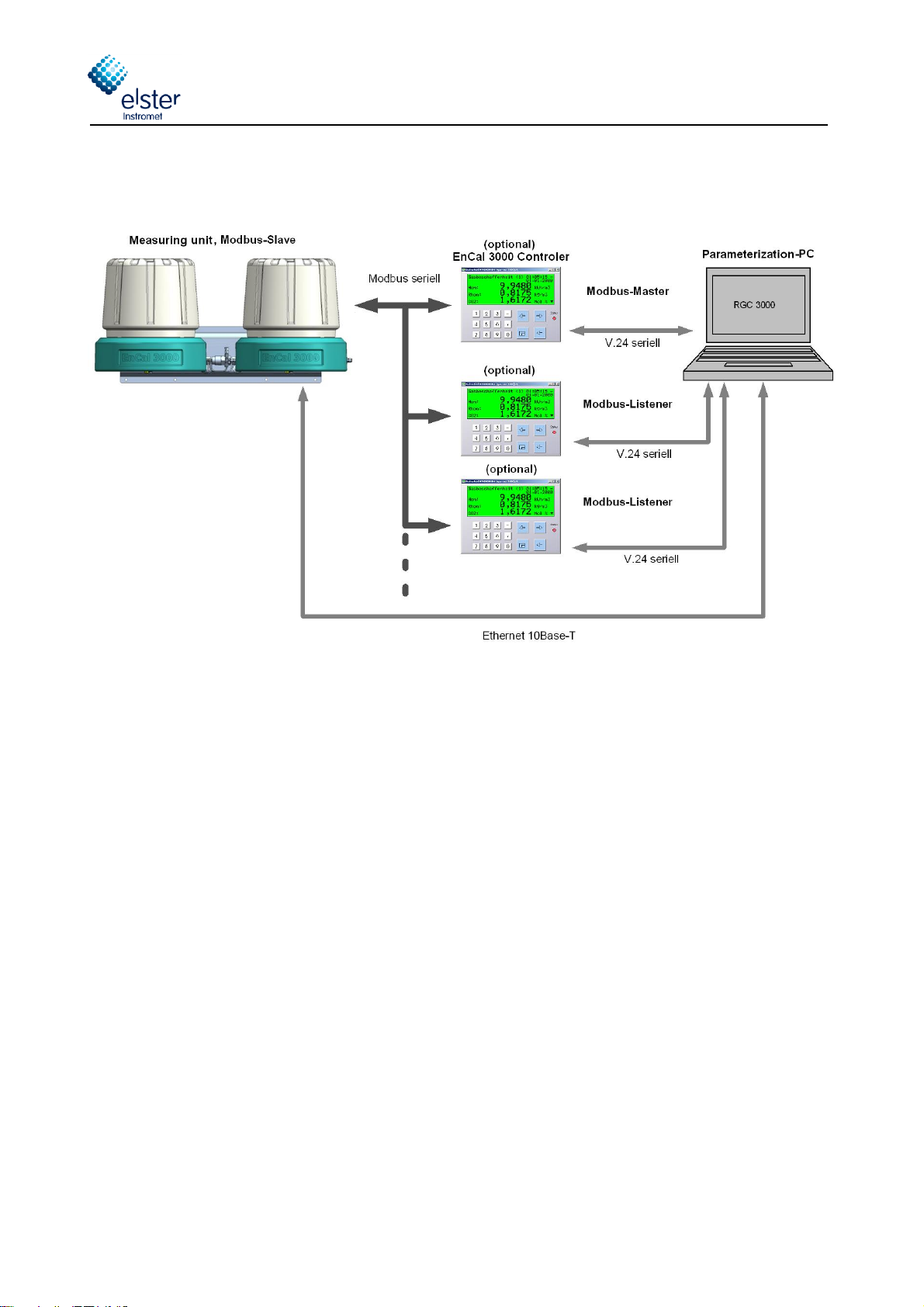
4Data Communication............................................................................................................................. 34
4.1 Local TCP/IP Data Communication .......................................................................................................34
4.2 Local Serial ModBus Data Communication .............................................................................................35
4.3 Remote Access ...................................................................................................................................36
4.4 ModBus Communication ......................................................................................................................37
5Hardware Installation ............................................................................................................................ 38
5.1 Installation specifications.....................................................................................................................38
5.1.1 Weight and Dimensions ........................................................................................................38
5.1.2 Installation clearance............................................................................................................38
5.1.3 Wall mounting .....................................................................................................................39
5.1.4 Connection of utilities ...........................................................................................................40
5.1.5 Connections to the EnCal 3000 Interconnection board .............................................................41
5.2 Hardware Start-up ..............................................................................................................................44
APPENDIX 1: CERTIFICATES ENCAL 3000 .............................................................................................. 46
APPENDIX 2: DECLARATION OF CONFORMITY ENCAL 3000 .............................................................. 52

Elster GmbH
___________________________________________________________________________________________________________
EnCal 3000 Quad–Hardware Manual 22/06/2017
3/52
Only Elster GmbH published User Manuals are to be used. Changes or translations of this User
Manual require the written consent of Elster GmbH.
All obligations of Elster GmbH arise solely from the contracts concluded and the General Terms and
Conditions applicable upon conclusion of the contract.
Warranty Conditions
You will find our current Warranty Conditions in the General Terms and Conditions, e.g.
on our website: www.elster-instromet.com/en/general-terms-of-business
Contact Information
Elster GmbH (Manufacturer)
Steinern Str. 19-21
55252 Mainz-Kastel / Germany
Phone:
+49 6134 605 0
Email:
Website:
www.elster-instromet.com
Technical Assistance Center:
Phone:
+49 231 93 71 10 88
Email:
Website:
www.elster-instromet.com

Elster GmbH
___________________________________________________________________________________________________________
EnCal 3000 Quad–Hardware Manual 22/06/2017
4/52
Safety Information
Electrical Safety
The EnCal 3000 Quad is a gas analyser designed to be installed in hazardous areas. For this purpose it is
certified according to:
ATEX II 2 G Ex d IIB T4 Gb and IECEx Ex d IIB T4 Gb
In compliance with:
IECEx:
IEC 60079-0: 2011 Sixth edition
IEC 60079-1:2014 seventh edition
ATEX:
EN 60079-0: 2012
EN 60079-1: 2014
Detailed information on this certificate can be found in APPENDIX
The operation and maintenance of such equipment should only be performed by qualified personnel.
Fuse replacement must only be performed by Elster GmbH authorized personnel.
The following basic rules must be observed in all circumstances:
The flameproof enclosure may not be opened when an explosive gas atmosphere may
be present. The process pressure shall be limited to 2 MPa to ensure that the pressure
rise inside the flameproof enclosure remains below 10 kPa. The functional pressure
must be lower see chapter 3 and section 5.1.4 containing the specifications. Before any
start-up, verify all connections of the unit for tight sealing. For information on the
dimensions of the flameproof joints the manufacturer shall be contacted.
WARNING! ELECTROSTATIC HAZARD!
Because of the potential electrostatic charging of the paint layer, the housings should
only be cleaned by using a moist cloth to prevent charging
BOTH CASES MUST BE EARTHED!
Important disclaimer:
If the equipment is used in a manner not specified by the manufacturer, the protection
provided by the equipment may be impaired.
Installation instructions mentioned in this manual are intended for information only. The installation of this
equipment must be conform to any national, local, or company codes applicable to the location. Elster-
Instromet assumes no responsibility for compliance with these requirements. It is suggested that a review of
the codes be made prior to installation.

Elster GmbH
___________________________________________________________________________________________________________
EnCal 3000 Quad–Hardware Manual 22/06/2017
5/52
Gas quality measurement system EnCal 3000 Quad
The EnCal 3000 Quad is a special version of the Encal3000. It contains two housings and can contain up to
four analytical channels.
This option has been developed especially for extended analysis applications that cannot be solved with only
two channels. A possible example is the combination of an analysis C9 with the two standard channels and
the additional analysis of hydrogen and oxygen with a third channel, and the analysis of hydrogen sulfide
and carbonyl sulfide with a fourth channel. With the simultaneous use of up to four channels, it is possible to
analyse all components in one system.
The measuring unit is the real gas chromatograph. It performs the analysis by measuring technology
autonomously. It is possible to install additional optional Encal3000 controllers. The subsystems
communicate with each other via Modbus (see Figure 1).
This manual describes the Hardware of the Encal3000 Quad gas chromatograph (measuring unit). The other
subsystems are described in separate manuals.
The parameterization of the measuring unit is done with the PC program "RGC 3000". The parameterization
of the optional Encal3000 controller is done with the PC program "Gas Works".

Elster GmbH
___________________________________________________________________________________________________________
EnCal 3000 Quad–Hardware Manual 22/06/2017
6/52
Basic configuration EnCal 3000 Quad (Measuring unit and an optional Encal3000 controller)
Fig. 1: Encal3000 Quad measuring system

Elster GmbH
___________________________________________________________________________________________________________
EnCal 3000 Quad–Hardware Manual 22/06/2017
7/52
1 Process Gas Chromatography –General Introduction
1.1 Analytical Principle
The analytical principle is shown in Fig. 1-1:
Fig. 1-1 Principle of a Gas Chromatography
A very small volume of sample gas (typically much less than 1 ml), which is a mixture of several
components, is injected into a stream of carrier gas, which takes the sample gas through the column. This
column acts as a separator through the difference in absorption rate of the different components of the
sample gas, they are separated from each other during their passage through the column and elute as
individual components. The concentration of each component is then measured at the end of the column by
a detector. From the knowledge of the concentrations of each component, any property of the gas can be
calculated.

Elster GmbH
___________________________________________________________________________________________________________
EnCal 3000 Quad–Hardware Manual 22/06/2017
8/52
1.1.1 Column
A GC column is a relatively long spiral of tubing with very small internal diameter. Typical dimensions of the
used columns in the Encal3000 Quad are a length of several meters and internal diameters of <0.1 mm.
They are made of inert materials like fused silica and stainless steel. Every GC column has a so-called
stationary phase inside, which acts as an absorption layer for the gas molecules flowing through the column.
Fig. 1-2 Different types of gas chromatographic columns
Various configurations are used depending on the components to measure:
Wall coated open tubular column: the stationary phase is a thin liquid layer coated on the
inner wall of the column (for example type 5CB)
Packed column: the stationary phase is coated on a packing, which is equally distributed
throughout the column (for example type HSA)
Support coated open tubular column: the stationary phase is a coated packing, which itself is
coated on the inner wall of the column (for example type M5S / molesieve)
Porous layer open tubular column: the stationary phase is a porous layer on the inner wall of
the column (for example type PPU)

Elster GmbH
___________________________________________________________________________________________________________
EnCal 3000 Quad–Hardware Manual 22/06/2017
9/52
1.1.2 Detector
In the natural gas industry, the most popular detector is the TCD: Thermal Conductivity Detector. It’s a
relatively simple, very efficient and very robust detector.
Another reason for the popularity of the TCD in the natural gas industry is the fact that gas chromatographs
are used mainly for the measurement of gas properties like heating value, Relative density and Wobbe
index. The calculation of these parameters is based on the concentrations of the main gas components.
TCDs newer design in MEMS technology (MEMS = Micro-Electro-Mechanical System), which are also used
in the Encal3000 Quad are much smaller in terms of volume. The components can be integrated at the same
time much more accurately, so that the analytical precision is for example 1 ppm for n-pentane.
Traditionally the two TCD’s (reference + measurement detector) are integrated in a so-called Wheatstone
configuration, which increases significantly the signal-to-noise ration of the measurement.
fig. 1-3 Typical electrical TCD circuit

Elster GmbH
___________________________________________________________________________________________________________
EnCal 3000 Quad–Hardware Manual 22/06/2017
10/52
1.1.3 Sample Injector
The sample injection must assure a precise injection of sample into the flow of the carrier gas.
In principle the amount injected must be very precisely controlled, both in volume, pressure, temperature and
flow (to avoid viscosity effects) to guarantee a high level of repeatability of the analytical results, but in
practice the normalisation of the measured concentrations will compensate for a large part of the fluctuations
of these parameters.
However, to reach a repeatability for the heating value below 0.02 %, these parameters do have effect and
need to be controlled to a high degree.
The used MEMS technology allows a fundamental improvement of the sample injection quality compared to
the traditional fine-mechanical technologies used for most of the current process GC’s on the market. The
picture below shows a typical MEMS sample injector, etched in silicon channel, with membrane valves to
control flow directions.
This injector allows for a very precise control of the injection volume and temperature, on a remote base.
fig. 1-4 MEMS Sample Injecto

Elster GmbH
___________________________________________________________________________________________________________
EnCal 3000 Quad–Hardware Manual 22/06/2017
11/52
1.2 Process Gas Chromatography
The Encal3000 Process Gas Chromatographs (PGC) transfers the core laboratory technique to process
conditions. Apart from the analytical performance specifications, a PGC therefore needs to be designed to
match the following specifications:
Explosion safety.
Extreme environmental conditions:
oHigh and low temperatures
oDust and precipitation
oElectro-magnetic influence
oWind
oCorrosive atmospheres
oVibrations and shocks
Complete stand-alone operation, no operator interference during normal operation:
oAutomatic and continuous analysis of different streams
oControl and processing of analytical measurement executed internally, no peripheral device
needed
oAutomatic calibration and verification
Standard maintenance limited to yearly intervals, without need for specifically trained people
oHigh reliability of the components
oHigh degree of protection to any contaminant (liquids, vapour or particles) in the sample gas
Analytical results available in industrial formats (for natural gas industry serial ModBus or ModBus
TCP/IP)
Internal data storage of all data, including averages, calibration data, events and alarms, during the
last 35 days, to permit the operator to retrieve data in the past in case the continuous analysis was
interrupted for any reason.
The EnCal 3000 Quad is designed to meet or exceed all of the above requirements. At the same time the
unit uses analytical technology which can compete with the highest standards used in the laboratory world,
surpassing any PGC currently used in the natural gas industry.

Elster GmbH
___________________________________________________________________________________________________________
EnCal 3000 Quad–Hardware Manual 22/06/2017
12/52
2 Functional Design
2.1 Introduction
The Encal 3000 Quad is the combination of two housings in one measurement System. In the two housings
is place for up to four analytical channels that are controlled by one processor board. This System has been
especially developed for extended analysis applications which cannot be solved with just two channels. One
possible example is the combination of a calorific value analysis up to C9, the analysis of hydrogen, oxygen
and the sulphur components hydrogen sulphide and carbonyl sulphide. For the analysis up to C9 the two
standard channels are used, for the analysis of hydrogen and Oxygen a third channel and for the sulphur
components a fourth channel is required. With up to four channels it is possible to analyse all typical
components of interest in one system.
The two housings are mounted on a metal plate to have a stable connection. The right housing, further
referred as “Master unit” contains the first two channels, the processor board for the control of the
measurement system and the sample selection. The left housing, further referred as “Slave unit” contains the
third and optionally fourth channel (depending in the application). Both housings have a separate power
supply board (interconnection board).
The slave unit shares the output of the stream selection in the master unit and therefore no additional stream
selection is needed. The required gas connections between the two housings are preinstalled.
The most important features of the Encal3000 Quad are:
Compact EX-d design
Complete stand-alone operation
Capillary and micro packed columns in combination with MEMS analytical components
Fast analysis (extended analysis of higher hydrocarbons up to C12 within 5 minutes)
Highest analytical performance available on the market :
oUncertainty < 0.1 % for a wide range of gases
oRepeatability < 0.02 %
Up to 5 sample streams sequential without external stream selection
Integrated sample system
Internal data storage for the last 35 days of all data
Suitable for extreme environmental conditions

Elster GmbH
___________________________________________________________________________________________________________
EnCal 3000 Quad–Hardware Manual 22/06/2017
13/52
The following paragraphs give a general description of the main parts of the measurement system.
2.2 Enclosure
The two enclosures of the Encal 3000 Quad are a custom EX
design, with various specific features.
Essentially the explosion proof enclosures are consisting of a low
base, to which a relatively high cap is attached through a screw
connection. Once the cap is removed from the base, almost all the
internal components are directly reachable:
Up to two analytical modules in each housing (which do
each a part of the total analysis, in parallel)
One Processor board (only in the Master Unit)
Internal sample system in the Master Unit (stream selection
and pressure regulation)
All electrical field connections like Ethernet, ModBus,
analogue IN, digital I/O, solenoid drivers, switches and
jumpers (only in the Master Unit) and fuses (in both Units).
Only if the Interconnection Board, which connects the analytical channels and the Processor Board, has to
be exchanged, the unit has to be taken apart. For all other check or maintenance procedures, only the cap
has to be removed.
The device can be mounted to the wall. The mounting holes at the back of each housing are used for the
connection of the housings. In this steel connection are some holes with a size of 8.5 mm available for the
connection to the wall.
The gas tubing (sample lines, cal gas and helium in and out, vent lines) and all electrical connections can be
directly connected to the Master Unit. Helium is connected also to the Slave Unit with the tubes between the
two units. If Argon is used as a second carrier gas for the Slave unit it is directly connected to it, all other gas
tubing are connected to the Master Unit.
The design of the enclosures is allowed for the extremists conditions imaginable in natural gas applications:
Explosion proof certified for ATEX II 2G Ex-d IIB T4 and IECEx (equivalent FM approval pending)
IP 66 ingress protection against dust and precipitation (suitable for offshore applications)
Standard temperature range: 0 to +55°C (32 to 130°F), optional extension
with internal heating to -20°C (-4° F), with internal heating and external insulation to -40°C (-40°F)
EMC certification according to EN 61000-6 - 2/4 (Industrial devices)
Vibration and shock test acc. IEC 60068-2-31 and 64
Coating according to Shell specifications DEP 40.4800.30 for off-shore applications

Elster GmbH
___________________________________________________________________________________________________________
EnCal 3000 Quad–Hardware Manual 22/06/2017
14/52
2.3 Assembly of major components and internal components
fig. 2-1 shows the exploded view of the different internal components of the Master Unit of the EnCal3000
Quad. The components in the slave unit are in principle the same, except that, the pressure regulators for
each stream and the processor board are not installed because they are only needed in the Master Unit.
The frame is used for mounting the components. It allows the removal of all the direct and individual
components, with the exception of the interconnection board. The components can be removed directly and
individually by unscrewing just a few screws.
If the Interconnection Board must be replaced, the frame has to be removed from the enclosure base first.
This arrangement permits the service engineer to easily review the board in case malfunctions would occur.
The detailed description of the functionalities of each component will be done in the following paragraphs.
fig. 2-1 Exploded View on the Internal Parts of the EnCal 3000 Quad

Elster GmbH
___________________________________________________________________________________________________________
EnCal 3000 Quad–Hardware Manual 22/06/2017
15/52
2.4 Channel
A channel consists of the following subcomponents:
Analytical Module. This is the heart of the EnCal3000: it contains the column, sample injector,
detector and the heaters for the columns and the injector
AMI (Analytical Module Interface): electronic circuit which controls the analytical components of the
Analytical Module. It has its own EDS (Electronic Data Sheets) which stores the local configuration
parameters
EPC: Electronic Pressure Control for adjusting the pressure of the analytical column
Channel Controller: electronic circuit which controls the communication between AMI and Processor
Board, and also controls the EPC (Electronic Pressure Control) and valves needed for the control of
the internal gas flow circuit.
Both AMI and Channel Controller have their own EDS (Electronic Data Sheets) which stores the local
configuration parameters. This enables to swap to channels without a need for reconfiguration, uploading the
internal settings is sufficient to fully install a new channel in an existing unit.
The Analytical Module uses different columns for different applications. In an EnCal 3000 Quad up to four
columns can be selected, the following columns are possible:
1.) HSA-0,4m Channel for Nitrogen, Methane, Carbon Dioxide, Ethane and Ethylene
2.) 5CB-8m Channel for higher hydrocarbons Propane to Nonane
3.) 5CB-4m Channel for higher hydrocarbons Nonane to Dodecane
4.) PPU-10m Channel for Hydrogen Sulphide, Carbonyl Sulphide, water vapour, methanol
5.) M5A-10m molesieve Channel for Helium, Hydrogen, Oxygen, Nitrogen and Carbon Monoxide
6.) 13CB-12 Channel for odorants like THT and TBM, Methylmercaptane and Dimethylsulphide (DMS)
7.) AL2O3-Channel for saturated hydrocarbons from Propane to n-Pentane and unsaturated
hydrocarbons like Propylene, Propadiene, i-Butene, 1-Butene, trans-2-Butene, cis-2-Butene and
1,3-Butadiene
8.) COX-1m for Helium, Hydrogen, Nitrogen, Methane, Carbon Monoxide, Carbon Dioxide and Ethane
For the M5A column, two additional internal humidity filters are required, which are mounted on the module.
These filters are used to reduce humidity to a minimum. Humidity can penetrate by diffusion of air into the
analytical column.
Without the filter, this humidity would reach the analytical module and be absorbed by the column material.
Therefore, the retention times of the measured components would reduce always so that the separation of
the measured components is deteriorated and a heating up of the column would be required after about 3
months.
With the filters ensures that a heating up of the M5A column is not necessary within a year (calibration
cycle). As the capacity of the attached filter is very low, the filter should be exchanged with each
recalibration. For the carrier gas argon always an additional external humidity filter should be used.

Elster GmbH
___________________________________________________________________________________________________________
EnCal 3000 Quad–Hardware Manual 22/06/2017
16/52
fig. 2-2 Overview of Channel Components
The next page shows the internal gas flow configuration of the channels.

Elster GmbH
___________________________________________________________________________________________________________
EnCal 3000 Quad–Hardware Manual 22/06/2017
17/52
fig. 2-3 Internal Gas Flow Circuit for each Analytical Channel of the EnCal 3000 Quad,
during Normal Operation (top) and sample Injection (below)

Elster GmbH
___________________________________________________________________________________________________________
EnCal 3000 Quad–Hardware Manual 22/06/2017
18/52
Detector
Solenoid V1
Solenoid V2
Solenoid V3
Solenoid V4
Solenoid V5
inlet
Solenoid V6
outlet
sample
loop
inject valve
Manifold block
Column vent
Reference vent
Sample vent
EGC/Ref vent
Sample
Injector
Analytical
column
Reference
column
Pump Manifold
Pressure
sensor
Pre
column
Pump sample valve
Pump valve
Backflush
valve
BF vent
Detector
Solenoid V1
Solenoid V2
Solenoid V3
Solenoid V4
Solenoid V5
inlet
Solenoid V6
outlet
sample
loop
inject valve
sample valve
Manifold block
Column vent
Reference vent
Sample vent
EGC/Ref vent
Sample
Injector
Analytical
column
Reference
column
Pump Manifold
Pressure
sensor
Pre
column
Backflush
valve
Pump
Pump valve
BF vent
fig. 2-4 Internal Gas Flow Circuit for each Analytical Channel with backflush of the EnCal 3000
Quad,
before activating backflush valve (top) and after activating backflush valve (below)

Elster GmbH
___________________________________________________________________________________________________________
EnCal 3000 Quad–Hardware Manual 22/06/2017
19/52
2.5 Processor Board
The main components of the board are:
Arm9 Processor
A Flash-Memory 32 MB for local data storage
The Ethernet-Port
Data communication ports (COM1-4) for serial Modbus, Analogue and Digital I/O
USB Port
I/O Controller for Communication to the analytical channels
Pressure- and Temperature Sensor
fig. 2-5 Processor Board connections
Save parameters in the measuring unit
Setting the "Configuration Jumpers" can protect the parameters on the measuring unit computer witch was
loaded by using the software RGC 3000. This configuration Jumper is on the mainboard (see fig. 2-6). If the
jumper is set, the parameters inside the measuring unit cannot be override.
Changes in the parameters can only be transferred to the measuring unit, if the jumper is not set. The setting
of the jumper can be checked on the display of the “instrument status” page. See Section 3.2 of the software
manual. How to set the jumper is shown in Figure 2.6.
Arm9
Processor
USB
DHCP
Switch
Configuration
Jumper
Digital I/O
COM2
COM1
Ethernet
Port
Analogue
I/O
SD-Card
Serial Ports
COM3 + 4
I/O Controller

Elster GmbH
___________________________________________________________________________________________________________
EnCal 3000 Quad–Hardware Manual 22/06/2017
20/52
fig. 2-6 Save parameters in the measuring unit
When installed in the EnCal 3000 Quad, two flat cables are making the connection between the
communication ports of the Processor Board and the Interconnection Board, which provides field
connections (Phoenix connector) for the data communication signals.
Table of contents
Other Elster Instromet Laboratory Equipment manuals
Popular Laboratory Equipment manuals by other brands

Qiagen
Qiagen QIAcube user manual

Sutter Instrument
Sutter Instrument MT-75 Series Assembly instructions

Hinds Instruments
Hinds Instruments EXICOR MicroImager user manual

Digitus professional
Digitus professional DN-95107 manual

MMM Group
MMM Group ECOCELL 22 operating instructions

Hach
Hach Lange 2100AN Instrument manual