Elster Instromet EnCal 3000 User manual

___________________________________________________________________________________________________________
EnCal 3000 – Hardware Manual 22/02/2018
EnCal 3000
Gas Chromatograph
Hardware Manual
73022344 LC 22.02.2018

Elster GmbH
___________________________________________________________________________________________________________
EnCal 3000 - Hardware Manual 22/02/2018
2/56
Contact In ormation...................................................................................................................................... 3
Sa ety In ormation ........................................................................................................................................ 4
Gas quality measurement system EnCal 3000............................................................................................. 6
1
Process Gas Chromatography – General Introduction................................................................... 7
1.1
Analytical Principle ................................................................................................................................ 7
1.1.1
Column ................................................................................................................................. 8
1.1.2
Detector ................................................................................................................................ 9
1.1.3
Sample Injector ................................................................................................................... 10
1.2
Process Gas C romatograp y .............................................................................................................. 11
2
Functional Design ................................................................................................................................ 12
2.1
Introduction ....................................................................................................................................... 12
2.2
Enclosure ........................................................................................................................................... 13
2.3
Assembly of major components and internal components ....................................................................... 14
2.4
C annel ............................................................................................................................................. 15
2.5
Processor Board ................................................................................................................................. 19
2.6
Interconnection Board ......................................................................................................................... 21
2.7
Cabinet Heaters .................................................................................................................................. 22
2.8
Internal sample system ....................................................................................................................... 23
2.8.1
Double Block and Bleed Function ........................................................................................... 25
2.8.2
Internal Sample Bypass ........................................................................................................ 25
2.9
Gas Connections ................................................................................................................................. 26
2.10
Breat er ............................................................................................................................................ 27
2.11
Cable Glands ...................................................................................................................................... 28
2.12
External Switc .................................................................................................................................. 28
2.13
Configuration wit two Carrier Gases .................................................................................................... 29
3
Technical Speci ications ..................................................................................................................... 30
4
Data Communication........................................................................................................................... 33
4.1
Local TCP/IP Data Communication ....................................................................................................... 33
4.2
Local Serial ModBus Data Communication ............................................................................................. 34
4.3
Remote Access ................................................................................................................................... 35
4.4
ModBus Communication ...................................................................................................................... 36
5
Hardware Installation......................................................................................................................... 37
5.1
Installation specifications ..................................................................................................................... 37
5.1.1
Weig t and Dimensions ........................................................................................................ 37
5.1.2
Installation clearance ............................................................................................................ 37
5.1.3
Wall mounting ..................................................................................................................... 38
5.1.4
Connection of utilities ........................................................................................................... 39
5.1.5
Connections to t e EnCal 3000 Interconnection board ............................................................. 40
5.2
Hardware Start-up .............................................................................................................................. 43
APPENDIX 1: Possible hardware options o the EnCal 3000............................................................... 45
APPENDIX 2: DECLARATION OF CONFORMITY ENCAL 3000 .............................................................. 51
APPENDIX 3: CERTIFICATE EC-Type Examination................................................................................ 55

Elster GmbH
___________________________________________________________________________________________________________
EnCal 3000 - Hardware Manual 22/02/2018
3/56
Contact In ormation
Manufacturer:
Elster GmbH
Steinern Straße 19-21
55252 Mainz-Kastel
Deutschland / Germany
Tel. ++49 (0) 61 34 / 605-0
www.elster.com
Aftersales/ Service Germany & International:
Elster GmbH
Schlossstrasse 95a
44357 Dortmund
Deutschland / Germany
Tel. ++49 (0) 231 93 71 10-88
Aftersales /Service International:
Elster-Instromet N.V.
Rijkmakerlaan 9
2910 Essen
Belgien / Belgium
Tel. ++32 (0) 3 6 700 700
e-mail: [email protected]
Or your local agent:
www.elster-instromet.com

Elster GmbH
___________________________________________________________________________________________________________
EnCal 3000 - Hardware Manual 22/02/2018
4/56
Sa ety In ormation
Electrical Sa ety
T e EnCal 3000 is a gas analyser designed to be installed in azardous areas. For t is purpose it is certified according
to:
ATEX II 2 G
Ex-db IIC T6 Gb
and IECEx
Ex-db IIC T6 Gb
Class I, Division 1. Groups B, C, D T6
Class I, Zone 1, AEx IIC T6 Gb
In compliance wit :
IECEx:
IEC 60079-0 : 2011
IEC 60079-1 : 2014
ATEX:
EN 60079-0 : 2012
EN 60079-1 : 2014
United States standards
Class 3600 : 2011
Class 3615 : 2006
Class 3810 : 2005
ANSI/ISA 60079-0 : 2013
ANSI/UL 60079-1 : 2015
NEC:
Detailed information on t is certificate can be found in APPENDIX

Elster GmbH
___________________________________________________________________________________________________________
EnCal 3000 - Hardware Manual 22/02/2018
5/56
T e operation and maintenance of suc equipment s ould only be performed by qualified personnel.
Fuse replacement must only be performed by Elster GmbH aut orized personnel.
T e following basic rules must be observed in all circumstances:
T e flameproof enclosure may not be opened w en an explosive gas atmosp ere may be pre-
sent. T e process pressure s all be limited to 2 MPa to ensure t at t e pressure rise inside t e
flameproof enclosure remains below 10 kPa. T e functional pressure must be lower see c apter 3
and section 5.1.4 containing t e specifications. Before any start-up, verify all connections of t e
unit for tig t sealing.
For information on t e dimensions of t e flameproof joints t e manufacturer s all be contacted.
WARNING! ELECTROSTATIC HAZARD!
Because of t e potential electrostatic c arging of t e paint layer, t e ousing s ould only be
cleaned by using a moist clot to prevent c arging
CASE MUST BE EARTHED!
Important disclaimer:
If t e equipment is used in a manner not specified by t e manufacturer, t e protection provided
by t e equipment may be impaired. Gases w ic are flammable or explosive under exclusion of
oxygen. (E.g. acetylene C2H2) s ould not be fed to t e measuring device.
Installation instructions mentioned in t is manual are intended for information only. T e installation of t is equipment
must conform to any national, local, or company codes applicable to t e location. Elster-Instromet assumes no responsi-
bility for compliance wit t ese requirements. It is suggested t at a review of t e codes be made prior to installation.

Elster GmbH
___________________________________________________________________________________________________________
EnCal 3000 - Hardware Manual 22/02/2018
6/56
Gas quality measurement system EnCal 3000
The gas quality measurement system EnCal 3000 consists in its basic configuration of a measuring unit and
an optional Encal3000 controller.
The measuring unit is the real gas chromatograph. It performs the analysis by measuring technology auton-
omously.
It is configured with the PC program "RGC 3000". It is possible to install an additional optional Encal3000
controller. The subsystems communicate with each other via Modbus (see Figure 1).
This manual describes the Hardware of the Encal3000 gas chromatograph (measuring unit). The other sub-
systems are described in separate manuals.
Basic configuration EnCal 3000 (Measuring unit and an optional Encal3000 controller)
Figure 1

Elster GmbH
___________________________________________________________________________________________________________
EnCal 3000 - Hardware Manual 22/02/2018
7/56
1Process Gas Chromatography – General Introduction
1.1
Analytical Principle
Gas c romatograp y in general is an analytical tec nology w ic is used to analyse gas mixtures, i.e. to measure t e
concentrations of t e different components of a gas.
T e analytical principle is s own in
fig. 1-1
:
ig. 1-1 Principle o a Gas Chromatography
A very small volume of sample gas (typically muc less t an 1 ml), w ic is a mixture of several components, is injected
into a stream of carrier gas, w ic takes t e sample gas t roug t e column. T is column acts as a separator t roug
t e difference in absorption rate of t e different components of t e sample gas, t ey are separated from eac ot er
during t eir passage t roug t e column and elute as individual components. T e concentration of eac component is
t en measured at t e end of t e column by a detector. From t e knowledge of t e concentrations of eac component,
any property of t e gas can be calculated.
Elster GmbH
___________________________________________________________________________________________________________
EnCal 3000 - Hardware Manual 22/02/2018
8/56
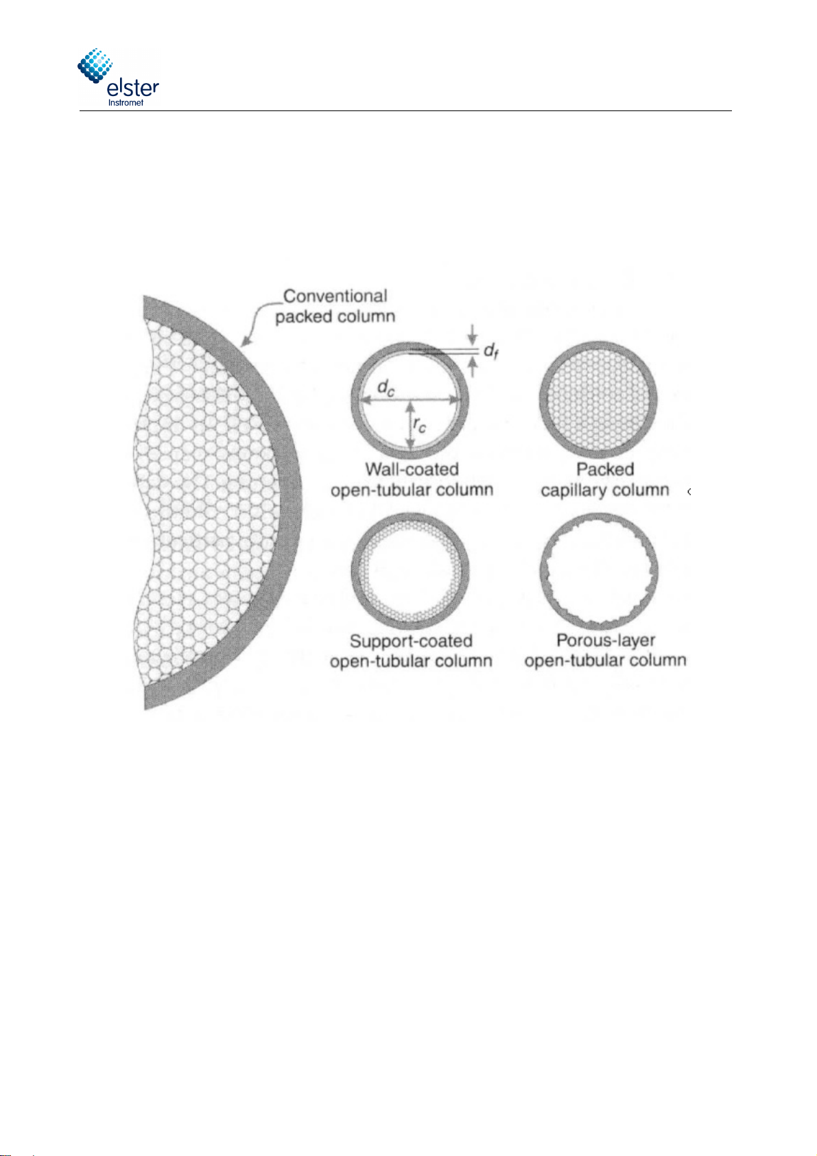
1.1.1 Column
A GC column is a relatively long spiral of tubing wit very small internal diameter. Typical dimensions of t e used col-
umns in t e Encal3000 ave a lengt of several meters and internal diameters of <0.1 mm. T ey are made of inert ma-
terials like fused silica and stainless steel. Every GC column as a so-called stationary p ase inside, w ic acts as an
absorption layer for t e gas molecules flowing t roug t e column.
ig. 1-2 Di erent types o gas chromatographic columns
Various configurations exist:
Wall coated open tubular column: t e stationary p ase is a t in liquid layer coated on t e inner wall of
t e column (for example type 5CB)
Packed column: t e stationary p ase is coated on a packing, w ic is equally distributed t roug out
t e column (for example type HSA)
Support coated open tubular column: t e stationary p ase is a coated packing, w ic itself is coated
on t e inner wall of t e column (for example type M5S mole sieve)
Porous layer open tubular column: t e stationary p ase is a porous layer on t e inner wall of t e col-
umn (for example type PPU)
Elster GmbH
___________________________________________________________________________________________________________
EnCal 3000 - Hardware Manual 22/02/2018
9/56
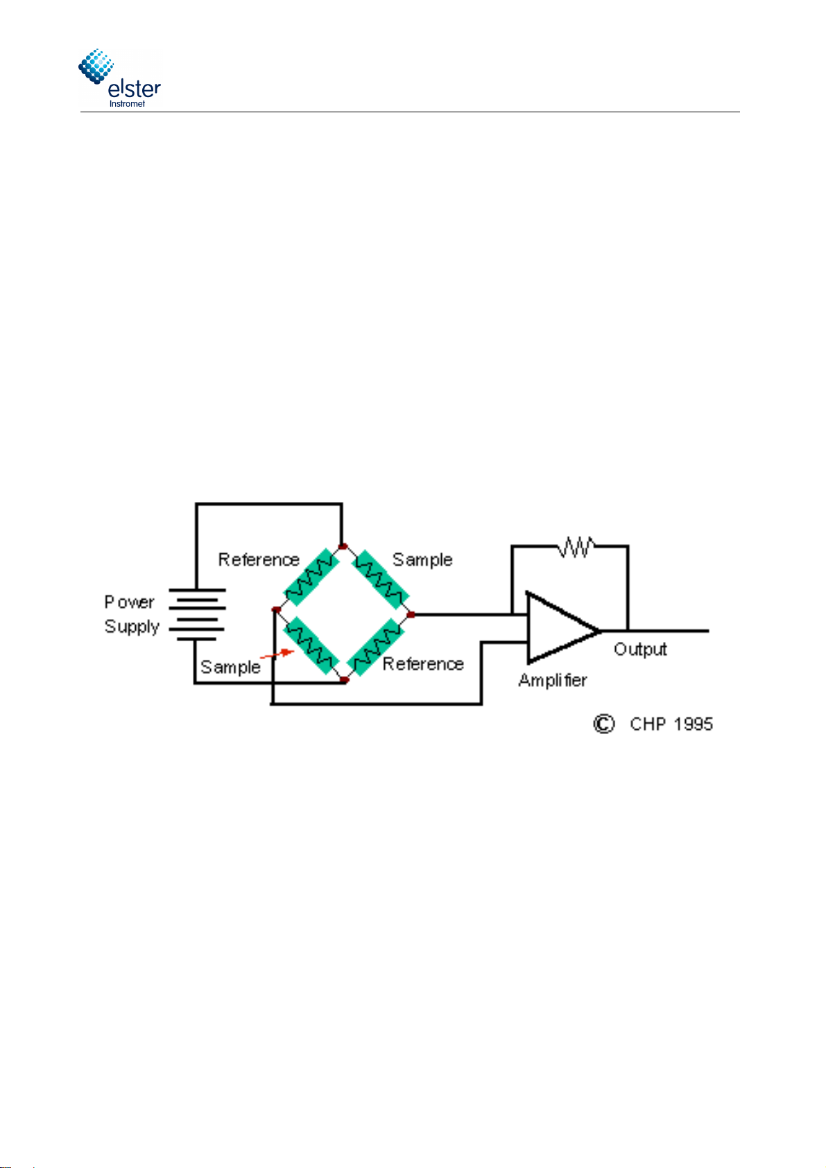
1.1.2 Detector
In the natural gas industry, the most popular detector is the TCD: Thermal Conductivity Detector. It’s a relatively simple,
very efficient and very robust detector.
Another reason for the popularity of the TCD in the natural gas industry is the fact that gas chromatographs are used
mainly for the measurement of gas properties like heating value, Relative density and Wobbe index. The calculation of
these parameters is based on the concentrations of the main gas components.
TCDs newer design in MEMS technology (MEMS = Micro-Electro-Mechanical System), which are also used in the Encal
3000 are much smaller in terms of volume. The components can be integrated at the same time much more accurately,
so that the analytical precision is for example 1 ppm for n-pentane.
Traditionally t e two TCD’s (reference + measurement detector) are integrated in a so-called W eatstone configuration,
w ic increases significantly t e signal-to-noise ration of t e measurement.
ig. 1-3 Typical electrical TCD circuit

Elster GmbH
___________________________________________________________________________________________________________
EnCal 3000 - Hardware Manual 22/02/2018
10/56
1.1.3 Sample Injector
T e sample injection must assure a precise injection of sample into t e flow of t e carrier gas.
In principle t e amount injected must be very precisely controlled, bot in volume, pressure, temperature and flow (to
avoid viscosity effects) to guarantee a ig level of repeatability of t e analytical results, but in practice t e normalisa-
tion of t e measured concentrations will compensate for a large part of t e fluctuations of t ese parameters.
However, to reac repeatability for t e eating value below 0.01 %, t ese parameters do ave effect and need to be
controlled to a ig degree.
T e used MEMS tec nology allows a fundamental improvement of t e sample injection quality compared to t e tradi-
tional fine-mec anical tec nologies used for most of t e current process GC’s on t e market. T e picture below s ows a
typical MEMS sample injector, etc ed in silicon c annel, wit membrane valves to control flow directions.
T is injector allows for a very precise control of t e injection volume and temperature, on a remote base.
ig. 1-4 MEMS Sample Injector

Elster GmbH
___________________________________________________________________________________________________________
EnCal 3000 - Hardware Manual 22/02/2018
11/56
1.2 Process Gas Chromatography
T e Encal 3000 Process Gas C romatograp (PGC) transfers t e core laboratory tec nique to process conditions. Apart
from t e analytical performance specifications, a PGC t erefore needs to be designed to matc t e following specifica-
tions:
Explosion safety.
Extreme environmental conditions:
oHig and low temperatures
oDust and precipitation
oElectro-magnetic influence
oWind
oCorrosive atmosp eres
oVibrations and s ocks
Complete stand-alone operation, no operator interference during normal operation:
oAutomatic and continuous analysis of different streams
oControl and processing of analytical measurement executed internally, no perip eral device needed
oAutomatic calibration and verification
Standard maintenance limited to yearly intervals, wit out need for specifically trained people
oHig reliability of t e components
oHig degree of protection to any contaminant (liquids, vapour or particles) in t e sample gas
Analytical results available in industrial formats (for natural gas industry serial ModBus or ModBus TCP/IP)
Internal data storage of all data, including averages, calibration data, events and alarms, during t e last 35
days, to permit t e operator to retrieve data in t e past in case t e continuous analysis was interrupted for any
reason.
T e EnCal 3000 is designed to meet or exceed all of t e above requirements. At t e same time t e unit uses analytical
tec nology w ic can compete wit t e ig est standards used in t e laboratory world, surpassing any PGC currently
used in t e natural gas industry.
Elster GmbH
___________________________________________________________________________________________________________
EnCal 3000 - Hardware Manual 22/02/2018
12/56
2Functional Design
2.1 Introduction
The EnCal 3000 is an on-line gas chromatograph that is housed in an EX-proof housing. In the housing is place for up to
two analytical channels that are controlled by one processor board.
T e most important features are:
Compact EX-d design
Complete stand-alone operation
Capillary and micro packed columns in combination wit MEMS analytical components
Fast analysis (C
6+
in less t an 3 minutes)
Hig analytical performance :
oUncertainty < 0.1 % for a wide range of gases
oRepeatability < 0.005 %
Up to 5 sample streams sequential wit out external stream selection
Integrated sample system
Internal data storage for t e last 35 days of all data
Suitable for extreme environmental conditions
T e following paragrap s give a general description of t e main parts of t e unit.
Elster GmbH
___________________________________________________________________________________________________________
EnCal 3000 - Hardware Manual 22/02/2018
13/56
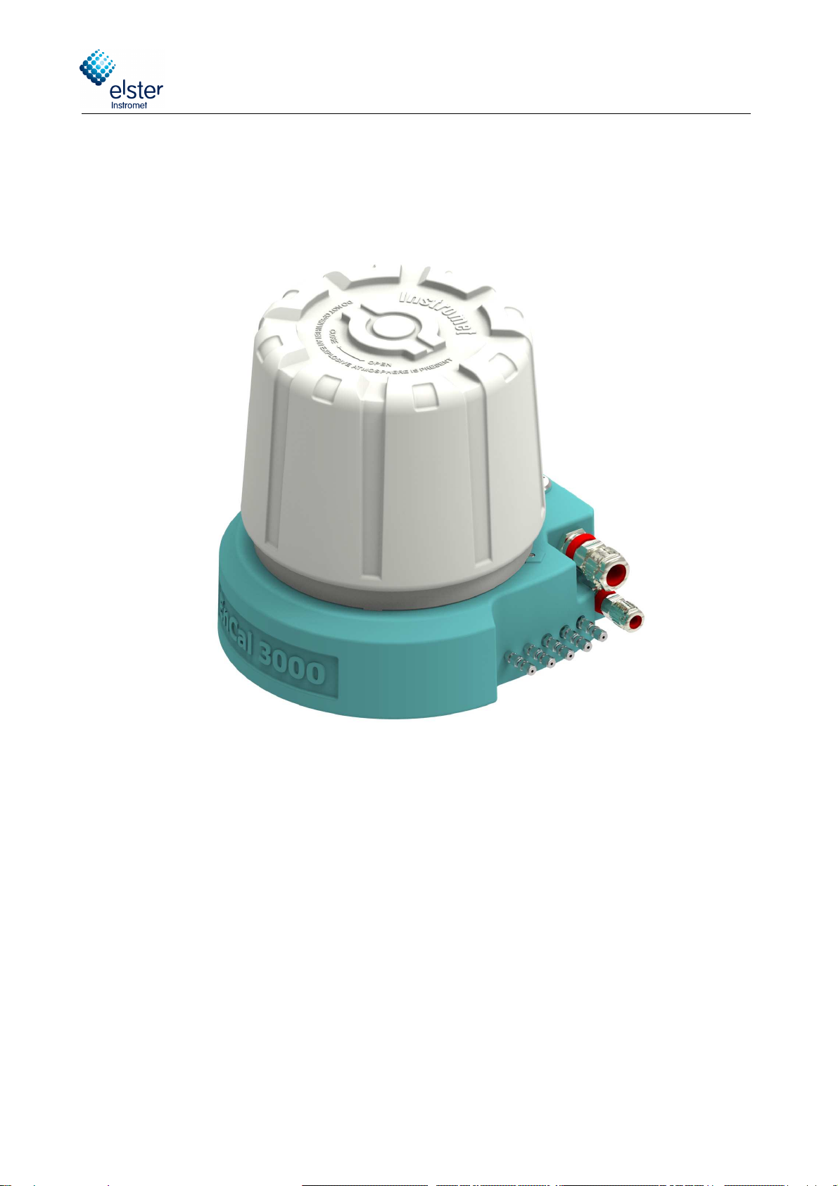
2.2 Enclosure
T e enclosure of t e EnCal 3000 is a custom EX design, wit various spe-
cific features.
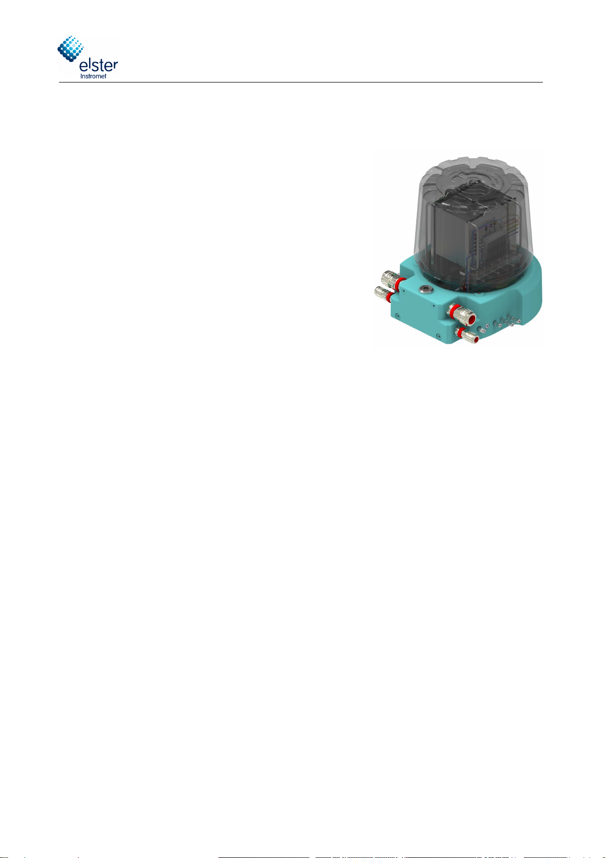
Essentially t e explosion proof enclosure consists of a low base, to w ic a
relatively ig cap is attac ed t roug a screw connection. Once t e cap is
removed from t e base, almost all t e internal components are directly
reac able:
Two analytical modules (w ic do eac a part of t e total analy-
sis, in parallel)
Processor board
Internal sample system (stream selection and pressure regula-
tion)
All electrical field connections (Et ernet, ModBus, analogue IN,
digital I/O, solenoid drivers), fuses, switc es and jumpers
Only if t e Interconnection Board, w ic connects t e analytical c annels and t e Processor Board, as to be ex-
c anged, t e unit as to be taken apart. For all ot er c eck or maintenance procedures, only t e cap as to be re-
moved.
T e compactness of t e unit (installation clearance Ø 55 cm x 70 cm eig t, weig t <30 kg) allows it to mount t e de-
vice on a platform, a pole or to t e wall. Mounting oles at t e back (M8) and in t e bottom (M5) allow for fixation.
All gas tubing (sample lines, cal. gas, vent lines, elium in and out) and all electrical connections can be directly con-
nected to t e unit.
T e design of t e enclosure allows for the harshest conditions imaginable in natural gas applications:
Explosion proof certified for ATEX / IECEx / NEC
IP 66 ingress protection against dust and precipitation (suitable for offs ore applications)
Standard temperature range: 0 to +60 ° C (32 to 140 ° F), optional extension for devices wit ATEX/IECEx-
Approval. 0 to 55°C (32 to 130°F) for devices wit FM-Approval
wit internal eating to -20 ° C (-4 ° F), wit internal eating and external insulation to -40 ° C (-40 ° F)
EMC certification according to EN 61000-6 - 2/4 (Industrial devices)
Vibration and s ock test according to OIML D11 11- 1/2
Coating according to S ell specifications DEP 40.4800.30 for off-s ore applications
Elster GmbH
___________________________________________________________________________________________________________
EnCal 3000 - Hardware Manual 22/02/2018
14/56
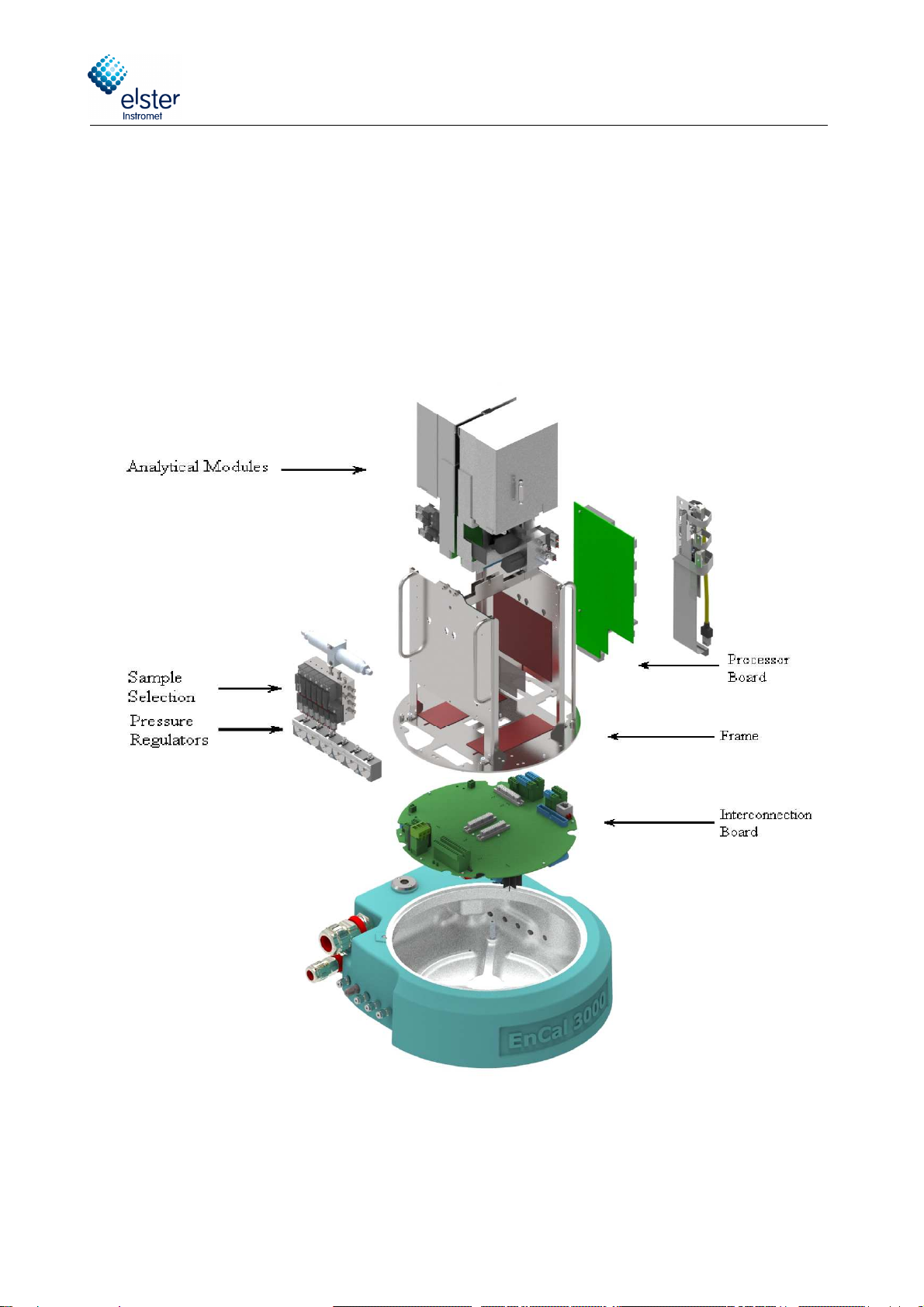
2.3 Assembly o major components and internal components
fig. 2-1 shows the exploded view of the different internal components of the Master Unit of the EnCal3000
The frame is used for mounting the components. It allows the removal of all the direct and individual components, with
the exception of the interconnection board. The components can be removed directly and individually by unscrewing just
a few screws.
If the Interconnection Board must be removed (bottom), the frame has to be removed from the enclosure base first. This
arrangement permits the service engineer to easily review the board in case malfunctions would occur.
T e detailed description of t e functionalities of eac component will be done in t e following paragrap s.
ig. 2-1 Exploded View on the Internal Parts o the EnCal 3000

Elster GmbH
___________________________________________________________________________________________________________
EnCal 3000 - Hardware Manual 22/02/2018
15/56
2.4 Channel
A c annel consists of t e following subcomponents:
Analytical Module: T is is t e eart of t e EnCal 3000: it contains t e column, sample injector, detector and t e
eaters for t e columns and t e injector
AMI (Analytical Module Interface): electronic circuit w ic controls t e analytical components of t e Analytical
Module. It as its own EDS (Electronic Data S eets) w ic stores t e local configuration parameters
EPC: Electronic Pressure Control for adjusting t e pressure of t e analytical column
C annel Controller: electronic circuit w ic controls t e communication between AMI and Processor Board, and
also controls t e EPC (Electronic Pressure Control) and valves needed for t e control of t e internal gas flow
circuit.
Bot AMI and C annel Controller ave t eir own EDS (Electronic Data Storage) w ic stores t e local configuration pa-
rameters. T is enables to swap to c annels wit out a need for reconfiguration, uploading t e internal settings is suffi-
cient to fully install a new c annel in an existing unit.
T e Analytical Module uses different columns for different applications. In t e EnCal 3000 two columns are used:
HSA column (HaySep), for t e analysis of N
2
, CH
4
, CO
2
and C
2
H
6
5CB column 4m or 8m, for t e analysis of t e ig er ydrocarbons (C
3
H
8
up to C
8
H
18
or up to C
9
H
20
)
For devices build before 2008 t e 5CB-4m c annel was used for t e analysis up to C6+ and t e 5CB-8m c annel just for
t e analysis up to C9. Since 2008 t e 5CB-8m becomes used for bot options, t e main reason for t is c ange is t at
t e separation of t e peaks especially for n-butane and neo-pentane is better for t e 8m long column.
Anot er possible C annel configuration for t e special application biogas is:
M5A column (molesieve), 10m long, for t e analysis of H
2
, O
2
and N
2
.
PPU column, 10m long, for t e analysis of t e ydrocarbons (CH
4
up to n-C
4
H
10
) and CO
2
Anot er possible C annel configuration for t e analysis of ydrogen and natural gas is:
•COX column, 1m long for the components (He), H2, N2, CH4, CO2 and C2H6
•5CB column, 8m long for the higher hydrocarbons (C3H8 to C9H20)
In t e biogas-application for t e M5A column, two additional internal umidity filters are required, w ic are mounted on
t e module. T ese filters are used to reduce umidity to a minimum. Humidity can penetrate by diffusion of air into t e
analytical column.
Wit out t e filter, t is umidity would reac t e analytical module and be absorbed by t e column material. T erefore,
t e retention times of t e measured components would reduce always so t at t e separation of t e measured compo-
nents is deteriorated and a eating up of t e column would be required after about 3 mont s.
Wit t e filters ensures t at a eating up of t e M5A column is not necessary wit in a year (calibration cycle). As t e
capacity of t e attac ed filter is very low, t e filter s ould be c anged wit eac recalibration. For t e carrier gas argon
always an additional external umidity filter s ould be used.

Elster GmbH
___________________________________________________________________________________________________________
EnCal 3000 - Hardware Manual 22/02/2018
16/56
ig. 2-2 Overview o Channel Components
T e next page s ows t e internal gas flow configuration of t e c annels.

Elster GmbH
___________________________________________________________________________________________________________
EnCal 3000 - Hardware Manual 22/02/2018
17/56
ig. 2-3 Internal Gas Flow Circuit or each Analytical Channel o the EnCal 3000,
during Normal Operation (top) and sample Injection (below)

Elster GmbH
___________________________________________________________________________________________________________
EnCal 3000 - Hardware Manual 22/02/2018
18/56
Detector
Solenoid V1
Solenoid V2
Solenoid V3
Solenoid V4
Solenoid V5
inlet
Solenoid V6
outlet
sample
loop
inject valve
Manifold block
Column vent
Reference vent
Sample vent
EGC/Ref vent
Sample
Injector
Analytical
column
Reference
column
Pump Manifold
Pressure
sensor
Pre
column
Pump sample valve
Pump valve
Backflush
valve
BF vent
Detector
Solenoid V1
Solenoid V2
Solenoid V3
Solenoid V4
Solenoid V5
inlet
Solenoid V6
outlet
sample
loop
inject valve
sample valve
Manifold block
Column vent
Reference vent
Sample vent
EGC/Ref vent
Sample
Injector
Analytical
column
Reference
column
Pump Manifold
Pressure
sensor
Pre
column
Backflush
valve
Pump
Pump valve
BF vent
ig. 2-4 Internal Gas Flow Circuit or each Analytical Channel with back lush o the EnCal 3000,
be ore activating back lush valve (top) and a ter activating back lush valve (below)
Elster GmbH
___________________________________________________________________________________________________________
EnCal 3000 - Hardware Manual 22/02/2018
19/56
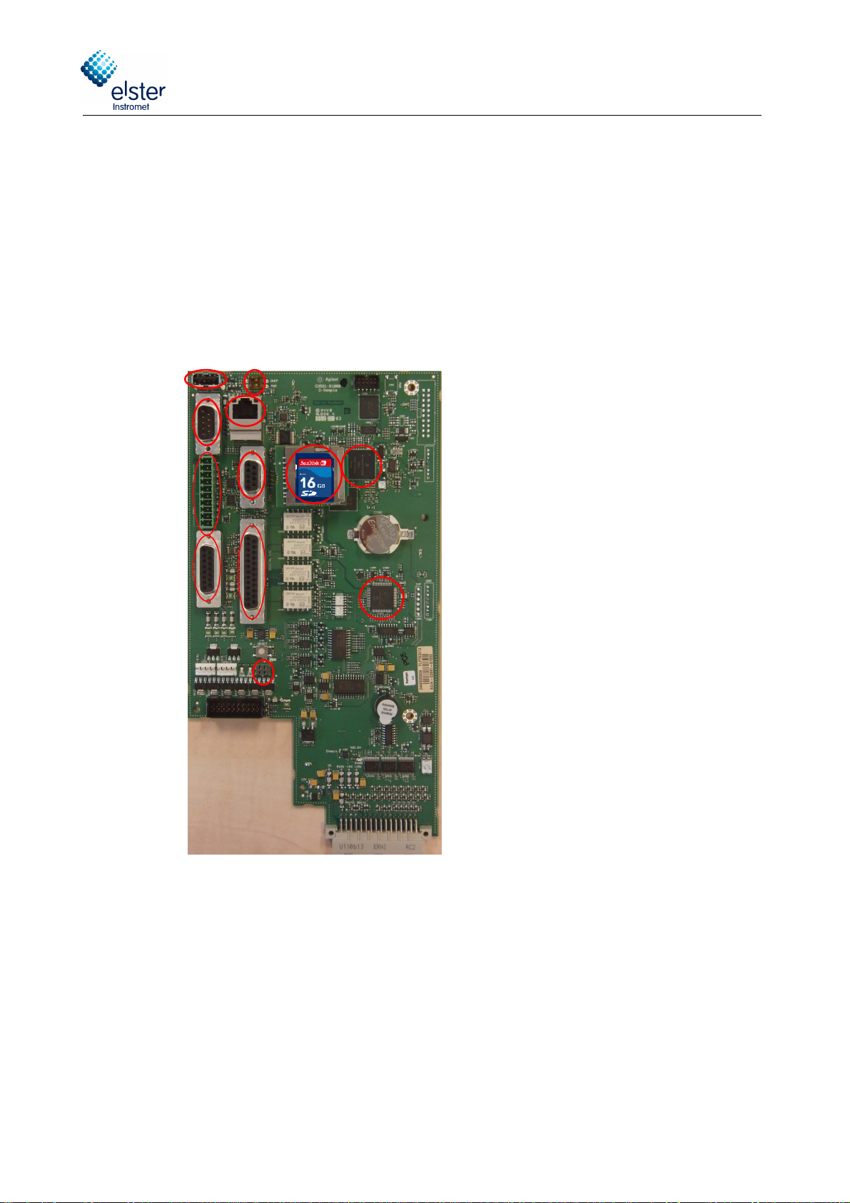
2.5
Processor Board
T e main components of t e board are:
Arm9 Processor
A Flash-Memory 32 MB for local data storage
The Ethernet-Port
Data communication ports (COM1-4) for serial Modbus, Analogue and Digital I/O
USB Port
I/O Controller for Communication to the analytical channels
Pressure- and Temperature Sensor
fig. 2-5: Processor Board connections
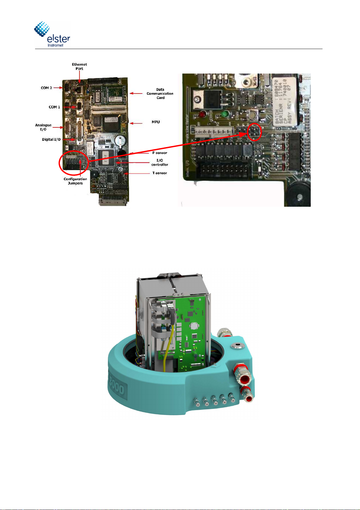
Save parameters in the measuring unit
Setting the "Configuration Jumpers" can protect the parameters on the measuring unit computer witch was loaded by
using the software RGC 3000. This configuration Jumper is at the same position for the old and the new mainboard.
If the jumper is set, the parameters inside the measuring unit cannot be override.
Changes in the parameters can only be transferred to the measuring unit, if the jumper is not set. The setting of the
jumper, can be checked on the display of the “instrument status” page. See Section 3.2 of the software manual. How to
set the jumper is shown in Figure 2.6.
Arm9
Proce
s
sor
USB DHCP
Switch
Configuration
Jumper
Digital I/O
COM2
COM1
Ethernet
Port
Analogue
I/O
SD-Card
Serial Ports
COM3 + 4
I/O Controller
Elster GmbH
___________________________________________________________________________________________________________
EnCal 3000 - Hardware Manual 22/02/2018
20/56
ig. 2-5 Save parameters in the measuring unit all bord versions
.
W en installed in t e EnCal 3000, a flat cable makes t e connection between t e communication ports of t e Processor
Board and t e Interconnection Board, w ic provides field connections (P oenix connector) for t e data communication
signals. Also 2 fans are mounted to cool t e processor in case of elevated ambient temperatures.
ig. 2-6 Processor board with ribbon lat cable and ans mounted in the EnCal 3000
Table of contents
Other Elster Instromet Laboratory Equipment manuals


Popular Laboratory Equipment manuals by other brands


Civco
Civco GUS G32-S Operator's manual

Burg Wächter
Burg Wächter BWnet-10120 quick guide

Agilent Technologies
Agilent Technologies 6890N Troubleshooting

ROMANOFF
ROMANOFF Yasui K2NEXT 8K product manual

Sigma
Sigma 6-16KS operating manual

Thermo Scientific
Thermo Scientific Heraeus Multifuge X1 Instructions for use


