Elston Manufacturing HC Heater User manual

Revision C1
11/2009
Elston
Manufacturing
HC Heater
Owners Manual

Table of Contents
Important Safety Information...........................ii
1) Description of Heater..........................................1
General information about your heater
including specifications
2) Quick Start Guide...............................................2
Basic instructions for using your heater
3) Ser ice Instructions............................................7
Recommendations on maintaining your heater
4) Troubleshooting Guide.......................................8
Detailed guide to help you diagnose and
fix problems fast
5) Installation Instructions...................................11
Ho to install and setup the HC heater.
Parts List...........................................................A1
Wiring Diagram...............................................B1
Revision B – Valid for models beginning ith Serial # 2424
i

Safety Information
Safety Information
The heater you have purchased as designed, first of all, to be safe. Ho ever, since this heater
burns propane and uses electricity, safety precautions are necessary for the safe and reliable
operation of this product. Throughout this manual, this important safety information ill be
highlighted in red.
Warning: Use Propane Only
This heater is designed to operate on propane only. Do not
attempt to use anything else as fuel since fire or explosion
may result.
Use this heater only ith regulators and tanks that provide
propane vapor at 11 inches of ater column.
Warning: Do Not Bypass or Substitute Safety
Equipment
Al ays use the regulator and excess flo valve supplied
ith the heater or a replacement that complies ith
Department of Transportation safety regulations.
Warning: Exhaust Gases
It is highly recommended that you use a carbon monoxide
detector henever people are regularly in the space heated
by this heater. Although this heater’s exhaust is completely
isolated from the inside air making it extremely unlikely
that any carbon monoxide ill enter the inside air, a carbon
monoxide detector is a necessary but inexpensive ay to
add another layer of safety.
Warning: Electrical Safety
Al ays disconnect po er from the heater hen performing
maintenance or inspection.
As always, apply common sense. If you’re not absolutely sure it’s safe then don’t do it.
ii

Chapter 1 Description
Description of Heater
The HC heater you have purchased is a thermostatically controlled propane heater. It is designed
to be mounted on the inside of the cab on heavy equipment or inside a small building.
It is a heavy duty forced air heater ith electronic ignition. To maximize safety, the combustion
air is completely separate from the inside air. The combustion air is dra n from outside, burnt
ith propane, heat is pulled from it to arm the inside air, and the exhaust exits outside.
Specifications
Dimensions.....................................................16 in ide x 11.5 in tall x 8 in deep
Weight..........................................................................................................27 lbs
Shipping Weight...........................................................................................32 lbs
Rating.................................................................................................19,000 BTU
Combustion Air Inlet Diameter........................................................................2 in
Exhaust Outlet...............................................................................1.5 in steel pipe
Hot Air Outlet Diameter..................................................................................6 in
Rated Voltage.................................................................................................12 V
Operating Voltage Range ( ith heater running)..................................11.5-13.5 V
Average Current Dra ................................................................................3 amps
Fuel Requirement........................................................................propane (LP gas)
Fuel Consumption............................................................................0.8 lbs/hr max
1

Chapter 2 Quick Start Guide
Quick Start Guide
Attention
The s itch on the side of the heater should not be used to turn
off the heater hen it is blo ing arm air as this ill
significantly shorten the life of some parts in the heater.
Instead, this s itch is designed as a emergency shutoff and to
shut do n the heater if it ill not be used for long periods of
time. Please turn do n the thermostat to turn off the unit
during normal operation.
Please read the previous page of important safety information if you haven’t already done so.
This guide assumes the heater has already been installed. For installation instruction please go to
chapter 5 (page 11).
For Instructions
Before Running the Heater for the First Time .....See Below
On Running the Heater for the First Time............See Page 5
On Running the Heater...........................................See Page 6
Before Running the Heater the First Time
Please take a moment to familiarize yourself ith your heater. The cover to the heater is attached
ith six bolts as sho n in Illustration 1 belo .
The combustion air enters in an opening on the bottom of the lo er left of the heater. It is
combined ith propane and burnt in the burner, travels through the heat exchanger , and exits
2
Illustration 1: O erall View of Heater

Chapter 2 Quick Start Guide
outside through the combustion air outlet on the bottom heater. The inside air is blo n over the
heater exchanger by the fan, here it captures the heat produced by the burning propane. This is
illustrated belo .
Near the heater, you ill see a thermostat. Please consult the manual that came for the thermostat
for instruction on ho to operate it.
A s itch, a green indicator light, and a red indicator light are located on the side of the heater
here the gas and the po er enter the heater. The s itch operates as a emergency off s itch; it
disconnects all po er to the heater. It should be used hen the heater is not needed for an
extended period of time and should not be used for shutting off the heater hen it is running or
for day to day operation. For day to day operation, the thermostat should be used instead since it
ill allo the heater to safely cool do n. The green indicator lights is on hen there is po er to
the heater and the internal circuit breaker has not tripped. The red indicator light is on hen the
safety system has checked out but the heater is either aiting to light or unable to light.
Normal Operation for Heater
When the s itch on the heater is off, the propane turned on, and the thermostat set to its
minimum setting, no lights ill be on or fans ill be running. When the s itch is turned on the
green indicator light ill come on. If the thermostat is turned up until the heater starts (this ill
be unnecessary belo 20 F), the blo er and fan ill start and after a short delay the red indicator
light ill come on. After a 15 to 30 second delay, the gas turns on, the red light turns off, and a
faint clicking noise ill be heard as the spark module sends a high voltage spark to the spark
probe. The heater ill attempt to light for approximately 10 seconds. If the heater lights, the red
light ill turn off. If not, the red light ill turn back on and the heater ill ait 15 to 30 seconds
to try again.
3
Illustration 2: Inside of HC Heater

Chapter 2 Quick Start Guide
The heater ill run until the trailer reaches the temperature set on the thermostat. The gas ill
turn off but the blo er ill run for an additional 2 to 3 minutes to cool do n the heater.
4

Chapter 2 Quick Start Guide
Running the Heater For the First Time or After the Unit Has Been Sitting
a Long Time
Whenever you need to verify that the heater is orking properly, please follo the four steps
belo .
1) Check the air inlets and outlets
Check that the air inlets and outlets are undamaged and unblocked, especially the ones that are
outside.
2) Check the fuel system
Check that the propane tank is securely mounted and the gas lines and fittings bet een the
propane tank and the heater are tight and undamaged. Turn on the valve on the propane tank.
3) Set the thermostat to the maximum alue
If the temperature is above 80 or 90 degrees, you may not be able to turn the thermostat high
enough for the heater to start in the next step. If you ish to continue setting up the heater you
ill need to chill the thermostat probe.
4) Turn on the heater
The heater ill start and, after a fe seconds, ignite. The red indicator light near the po er s itch
ill turn on until the heater has ignited. You should hear it quietly ignite just after the fan turns
on and you ill feel the air exiting the heater get arm ithin a minute. If the heater doesn’t
ignite after a fe minutes (the red indicator light ill turn on and stay on), please refer to the
troubleshooting guide to help fix the problem.
5) Set the thermostat to the desired temperature.
Your heater is no ready for use.
5

Chapter 2 Quick Start Guide
Normal Operation
1) Check the air inlets and outlets
Check that all the air inlets and outlets are undamaged and unblocked.
2) Check propane supply
Check that the propane tank(s) are securely mounted and contains fuel. Check that the fitting
connecting the tank to the gas system is tight. Turn on the valve on the propane tank.
3) Set the thermostat
Set the thermostat to the desired temperature.
4) Turn on the heater
Your heater is no ready for use and ill automatically run as necessary to maintain the space at
the desired temperature (just like a home furnace.)
5) Turning off the heater
If you need to turn the heater for the night or the eekend, turn off the heater using the
thermostat. This guarantees than the heater has time to cool do n properly.
If you need to turn the heater off for longer than a fe days, turn off the heater using the po er
s itch on the side. It is very important that the heater is not running hen you shut off the po er.
If the heater is running, first turn off the heater using the thermostat, ait until the fan as
stopped, and then turn off the heater. Turning off the heater ith the po er s itch hile it is
running is not inherently dangerous, but it ill reduce the life of some of the components inside
the heater. Once the heater is turned off, close the valve(s) on the propane tank(s).
6
Chapter 3 Service Instructions
Ser ice Instruction
E ery time you walk by the heater (and at least once a week)
•Check the air inlet and the exhaust outlet for damage or obstructions
•Check the exterior gas lines for damage
Annually before the start of the winter season
•Carefully inspect the propane tank, regulator, and fuel lines. Replace any damaged
components and tighten any loose fittings.
•Clean the air inlet and the exhaust outlet. Remove any debris that has collected turning
the summer.
•Remove the heater cover. Carefully remove any dust or dirt from the grill and the large
fan inside the heater.
•Start up and run the heater for a couple of minutes to check that everything is in orking
order.
•If you are using a digital thermostat, replace its battery.
E ery three years (or when ignition problems occur)
In addition to the annual maintenance,
•Remove the spark probes and check them for damage and deposits. They should not be
darker than a light gray or have an excessively rounded tip. If the spark probes are
damaged or excessively rounded, they should be replaced. If the spark probe has deposits
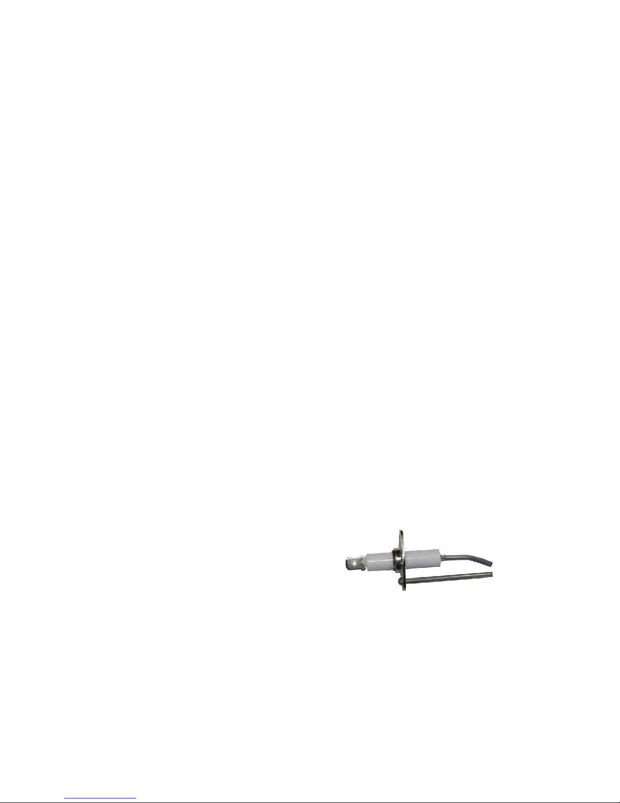
then carefully remove them ith a damp rag or abrasive plastic pad. Illustration 3 belo
sho s the original condition of the spark probe as a reference. When you reinstall the
spark probe al ays use a high
temperature antiseize compound rated for
at least 1200F on the threads of the
mounting scre and, if necessary, seal
the joint bet een the spark probe and the
combustion chamber ith a high
temperature exhaust or furnace cement
rated to at least 900F. Be careful to avoid
getting any cement on the mounting
scre to allo future removal of the
sparker.
7
Illustration 3: Spark Probe as Originally
Installed

Chapter 4 Troubleshooting
Troubleshooting
If this guide doesn’t fix your problem please contact the company here you purchased the
heater. If you are unable to contact them or you need additional help, please contact Elston
Manufacturing at 1-800-845-1385.
Warning
For your safety, the propane should al ays be turned off hen
troubleshooting this product. Al ays keep the po er to the
heater off hen orking inside the heater.
What is wrong with the heater?
A. Heater fails to ignite and fan does not run.
B. Fan runs but heater fails to ignite.
C. Heater usually ignites but sometimes does not.
D. Black smoke from exhaust outlet
Problem: Heater fails to ignite and the fan ne er runs.
Turn do n the thermostat and turn off po er to the heater using the s itch.
Does the green indicator come on when the power is turned on?
No. Check that the heater is receiving po er and the positive and ground have not been
reversed. If voltage is not detected, do a quick inspection of the electrical system from the
heater to the vehicle for obvious problems. If there are no obvious problems, It is
recommended that you start at the thermostat and ork your ay through the components
supplying po er from the vehicle to the heater until you find the problem. Possible
problems include loose connections at terminal bolts, corrosion or mechanical damage to
ires, and tripped circuit breakers and blo n fuses.
Yes, but just for a moment. There is probably a short inside the heater. Check for loose
or damaged ires and connections.
Yes. If you turn up the thermostat all the ay does the red light turn on immediately?
No If applicable, check that the thermostat is turned on and set to heat. Check
that temperature of the thermostat is set high enough that it ill turn on the
heater. If the thermostat is a digital model, replace the batteries. If none of these
things ork, check that +12 volts DC is coming into the thermostat from the
heater and there are no loose connections inside the thermostat.
If the thermostat is orking correctly, check that the heater is receiving at least
10VDC. The heater needs at least 11 VDC to function correctly but may fail to
function completely belo 10 VDC.
8

Chapter 4 Troubleshooting
Yes The safety system for the heater does not have the correct initial setup.
Check that the flap for the sail s itch is not stuck in the open position. If the sail
s itch is not physically stuck open, check that the resistance across the sail
s itch is above 1 MΩ hen the heater is off. If the resistance is belo this valve,
the sail s itch needs replacement.
Problem: Fan Runs But Heater Fails to Ignite
With the gas off, start the heater by turning up the thermostat to the maximum temperature. The
red light should turn on a couple seconds after the fan starts and you should hear a faint clicking
noise fifteen to thirty seconds after the blo er starts. If you do, then:
Rule out general problems. Carefully check the fuel system. Check that the propane
tanks contain fuel, all gas lines are undamaged, and all fittings are tight. Check the
connections at the thermostat for problems. Remove the cover of the heater and check the
iring for damage or loose connections and the components in the heater for obvious
damage. Check that the heater is getting at least 12 VDC.
Inspect the spark ignition system. The spark ignition system should create one spark
across the tip of the spark probe in the combustion chamber on each faint click. The spark
can be in an incorrect location for any of the follo ing reasons: damage to the spark
probe ire, loose connections, and deposits on the spark probe. To access the spark probe
to check it for deposits, removing the access panel on the side of the heater by the
combustion chamber. The metal tips of the spark probe should only be slightly rounded
ith an 1/8” gap at the tip. In addition, the insulator on the probe should have no cracks
or chips missing and only have light deposits on the insulator. If the spark probe is
damaged or excessively round, it should be replaced. If the spark probes only has
deposits, carefully remove them ith a damp rag or abrasive plastic pad.
The small blower may not be working. With the gas off, check that air is flo ing
though the combustion chamber and that the small blo er is turning. If it is not orking,
check for loose connections or obstructions or damage to the blo er. If you find nothing
obvious, remove the blo er and test it at 12 VDC to see if it is functioning correctly.
If the red light does not come one and you don't hear the faint clicking noise then
The sail switch or high temperature switch may be malfunctioning. If the sail s itch
fails to close or the high temperature s itch is stuck open the heater ill not attempt to
ignite. Also loose or damaged ire to either of these items ill cause the same problems.
Check the iring to these t o items. With the po er off to the heater, use a multimeter to
check that the resistance of the the high temperature s itch is less than 1 ohm. If it is
higher, it should be replaced. Also, check if the sail s itch closes hen the heater runs by
disconnecting the iring to the sail s itch and checking if the resistance drops to zero
hen the fan is running. If the iring and t o s itches check out ok, refer to the
troubleshooting tips above for this problem.
If the red light comes on but you don't hear the faint clicking noise then
This indicates either a short in high oltage line or a malfunctioning ignition
module. Check the high voltage line for damage. If no problems are found, remove the
high voltage ire from the spark probe on the combustion chamber (it can be accessed by
removing the access panel on the side of the heater by the combustion chamber). With the
9

Chapter 4 Troubleshooting
gas off, double check that no spark is being produced by improving a 1/8” spark gap from
the end of the high voltage terminal to the combustion chamber. If a spark is being
produced, remove and inspect the spark probe. Check and fix any possible shorts, adjust
the spark gap to 1/8” if necessary, and reinstall the spark probe. If this does not fix the
problem refer to the troubleshooting tips at the start of this problem. If no spark is being
produced, the spark ignition module needs to be replaced.
Problem: Heater usually ignites but sometimes does not
Check that the propane tank is not lo and gas is getting to the heater.
Is any extra duct ork connected to the exhaust or air inlets or outlets?
Yes. The heater should have less than 5 feet connected to the hot air inlet and outlet . Any
additional pipe connected to the exhaust should be 1.5-inch or larger pipe less than 2 ft
long. Disconnect all duct ork to the heater to see if this corrects the problem.
No Carefully check all the inlets and outlets and blo er for debris and obstructions.
Follo the trouble shooting suggestions for problem B. In addition, use a voltmeter to
check if the heater is getting sufficient voltage hile it is on. It should be 11.5 to 13.5V
for the heater to operate reliably. The heater ill operate on 11 to 11.5V but poor ignition
and carbon deposits are a possibility.
Problem D: Black Smoke from Exhaust Outlet
Under normal use, the heater ill produce very little, if any, black smoke near the exhaust outlet.
A hite “smoke” of ater vapor is normal during cold eather but darker smoke is often the first
sign of a problem ith the heater and often sho s up first hen the vehicle po ering the heater is
not running. These deposits typically indicate that one of the openings in the heater is obstructed
or the heater is not receiving enough voltage hile it is running.
Check if the heater is running off of the battery only (ie the vehicle is not running). If the battery
is significantly run do n or running many accessories, the heater cannot receive enough voltage
to operate properly. Running the heater for less time on the battery or starting the vehicle should
correct the problem.
If this problem occurs hen the vehicle is running or after less than an hour of running on the
battery, check the follo ing:
1) Check that none of the inlets or outlets to the heater are partially blocked or any duct ork
leading to or from the heater is damaged.
2) Check that the heater is receiving a voltage of at least 11.5 VDC at the thermostat hile
the blo er is running. A voltage belo 11.5 VDC typically indicates a problem in the
electrical system bet een the heater and the vehicle. Start by looking for loose or
corroded connections.
3) Check that the regulator is producing the correct pressure of 10.5-11 inches ater
column. A high pressure ill cause the heater to receive too much propane.
10

Chapter 5 Installation
Installation
Warning: Improper installation of this heater creates a substantial safety hazard
including the risk of property damage, fire, death.
Attention: Compliance ith local regulations is the responsibility of the
installer. If you are unsure hat local regulations require, please refer to the
current regulations in your area or speak ith the authority having jurisdiction
before beginning installation.
5.1 O er iew
The choices you make in installation have huge effects on the safe and reliable operation of this
heater. There are four primary issues to focus on:
1. Safe and robust installation of the propane fuel system
2. Safe and robust installation of the electrical system
3. Secure mounting of all parts against long-term vibration
4. Ensuring adequate and consistent air flo to the heater
These purpose of these instructions is to aid you in installing a fully functional heater that is safe
and secure under both normal condition and, as much as possible, during an accident. Ho ever
these instructions are not a substitute for personal kno ledge and experience ith installing
propane and/or electrical systems. Please do not install those areas of the heater unless you have
personal kno ledge and experience in these areas.
These instructions ere ritten ith the latest standards for the US and Canada in mind and are
intended to guide you in an installation that meets these standards. At the time of riting, the
latest standards ere the 2008 edition of NFPA 58, the Liquefied Petroleum Gas Code and the
2005 edition CAN/CSA-B149.5-05, Installation Code for Propane Fuel Systems and Tanks on
High ay Vehicles. Ho ever, if the regulations that apply in your area conflict ith these
installation instructions the local regulations should al ays be follo ed instead.
Throughout this guide, the ord “must” is used for any instruction that if not follo ed ould
create a safety hazard and/or yield an installation that ould not comply ith current standards.
An instruction ith the ord “should” is necessary either for the proper functioning of the
product or improves the long-term safe operation of the product. If you are unable to follo any
instructions ith the ords “must” or “should”, please contact us and/or the authority responsible
for regulating or approving your installation to discuss ho your installation can be still be
completed in a ay that is functional, safe, and compliant. Finally, an instruction that
recommends indicates an instruction designed to maximize the orking life of the product,
simplify installation, or improve the appearance of the installed product.
5.2 Unpacking the Heater and Gathering Supplies
Parts Needed for Installation Included with Heater:
•1 template for mounting holes
11
Chapter 5 Installation
•6 feet self stick rubber seal
•1 exhaust flange and gasket
Additional parts required:
•4 1/4” bolts at least ½ inch longer than the thickness of the all the heater is being
mounted on ith ashers, lock ashers, and nuts to match.
•Hard are to attach the thermostat and exhaust flange
•Length of 18ga stranded ire
•Brackets and clips for attaching fuel lines, electrical lines, and thermostat probe to the
trailer alls
•Propane fuel system including tanks, tank holders, and propane hoses
5.3 Heater placement:
The heater should be located here it is not in the ay of normal traffic and, if possible, ith
enough clearance to remove the cover to the heater and the access panel for the spark probe
ithout unbolting the heater. If you are unable to mount the heater in a position that the on/off
s itch and indicator lights are easily accessible, a remote box is available as an accessory.
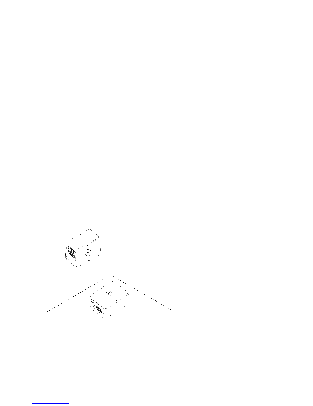
The heater must be mounted in one the orientations sho n belo ith plenty of room for the air
to enter and leave the heater.
Acceptable Mounting Positions
Position A – Floor Mount
The heater may be installed in any position
here the exhaust exits the heater straight
do n.
Position B – Horizontal Wall Mount
The heater may be mounted on the all
provided it is mounted as pictured (the air
inlet is on the left and the air outlet is on the
right hen facing the cover of the heater).
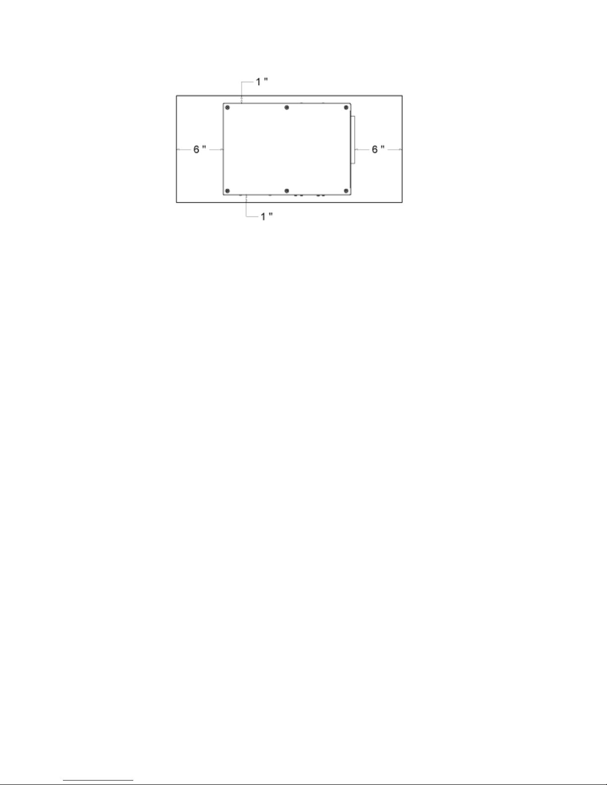
In order to ensure adequate air flo for the heater to operate properly, the cold air inlet and hot air
outlet must be 6” or more from a all or obstruction. In addition, the sides and top of the heater
must have at least 1” of clearance from nearby objects.
12
Illustration 4: Mounting Positions
Chapter 5 Installation
5.4 Mounting
Check that the template matches the heater. Tape the drilling template in the desired location for
the heater, checking that it is level and flat. Center punch the location of the air inlet and outlet
holes and one of the top mounting holes indicated on the template. Remove the template and
identify the size of the holes on the all. If you are cutting the larger holes ith a jigsa or saber
sa , use a compass to mark the circles.
Drill all three holes to the size indicated on the template.
Lift the heater into place and align it ith the mounting holes. Once the heater is lined up, slide a
1/4” bolt ( ith a asher) into the top mounting hole you drilled. If desired, finger tighten the nuts
on this bolt to keep the heater from pulling a ay from the all. Level the heater and mark the
other three mounting holes. Remove the heater and drill the remaining holes. Lift the heater into
place and install and tighten all four mounting bolts
If desired, install the included exhaust coupling to allo redirection of the exhaust or to protect
the mounting surface of the heater from damage. A fiberglass paper gasket is included for
insulation bet een the coupling and the mounting surface for the heater.
Mount the thermostat. Select a location here it may be easily accessed and it is a ay from
drafts. If the thermostat has a remote temperature probe, mount this on a surface that is expected
to be the same temperature as hat you are heating. In other ords, don't mount the probe near
the ceiling, the hot air outlet, or on a cold metal surface.
5.5 Wiring
The high levels of vibration and the temperature extremes these heaters are exposed to is hard on
electrical connections. Al ays use quality electrical connectors, fittings, and ire as clean, secure
connections are essential for both the proper operation of this heater and long-term trouble-free
operation.
Run ires from the thermostat to the heater and from the vehicle to the heater. These ires must
be secured to the all of the vehicle and should be stranded ire of at least 18ga. Thinner ire
can ork for the thermostat but the joints and connections tend to be much less resistant to long-
term vibration. Trim the ire so that it can extend at least 6” past the grommet and into the
heater.
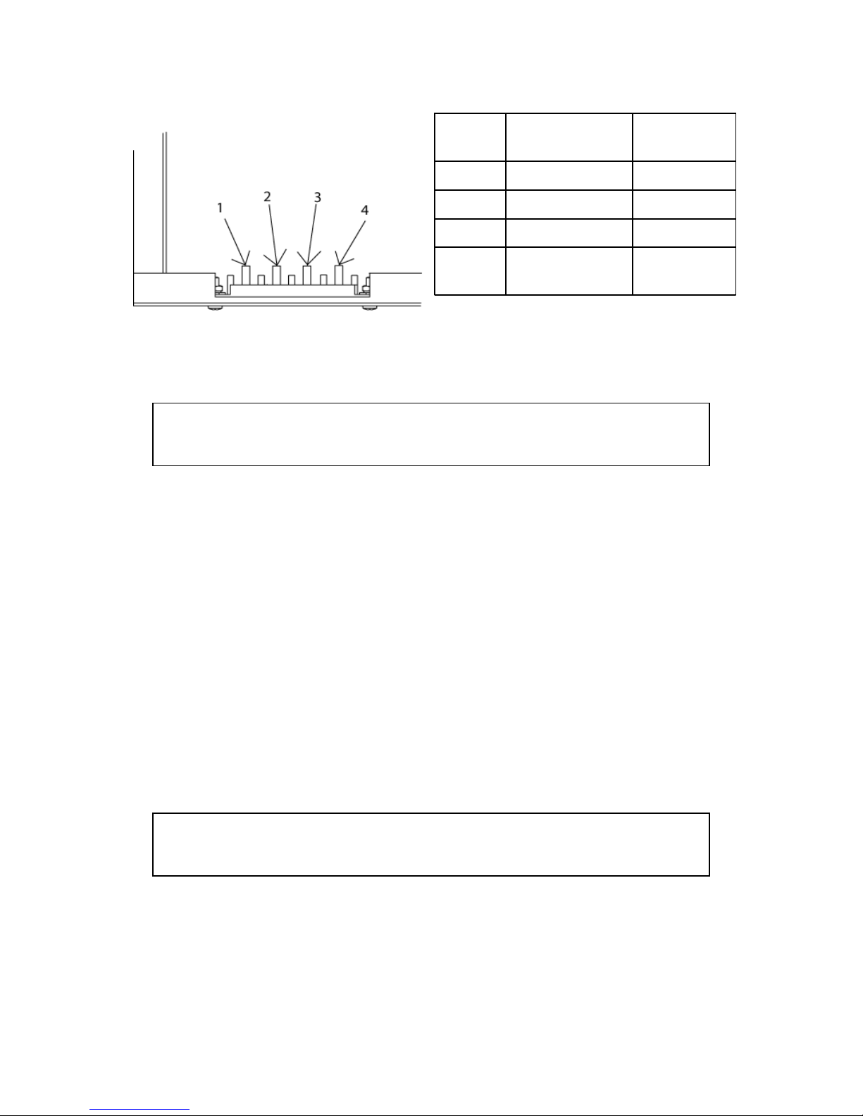
Check that the po er to the heater is off. Connect the ires to the terminal block. T o of the
terminals are po er into the heater and the other t o terminals are for the thermostat.
13
Illustration 5: Mounting Clearances
Chapter 5 Installation
Fuel System
Attention: These instructions are intended for general guidance only. Consult
the current regulations in your area or the latest standards, NFPA 58 for the
United States or CAN/CGA 149.2 for Canada, for exact requirements.
Before you begin mounting any components, it is recommended that you determine the
approximate mounting location of all components to ensure that all parts can be connected ith
the available lengths of hose and tubing. The recommended order of installation is:
1) Install the propane tanks or propane tank carriers.
All propane tanks must be “DOT” or “ASME” approved, setup for vapor ithdra al,and
mounted in line ith the manufacturer's instructions and the applicable code.
Install the propane tank or propane tank carrier, such as the X-1025 or X-1050, follo ing
the instructions included ith product. Installation instructions are available for all tanks
purchased from Elston Manufacturing. If your tank or tank carrier does not have
instruction, contact the manufacturer for guidance and refer to the installation code that
applies in your area.
Any tanks should be mounted at least 18” from any portion of the exhaust system for the
heater or the vehicle. If this is not possible, it must be shielded from the exhaust
components by a vehicle frame member or a baffle of noncombustible material. The item
that is shielding the tank must have an air space bet een itself and the exhaust
component and itself and the tank to properly shield the tank from heat. If a baffle is
used, it should be constructed so that it is expected to resist corrosion at least as long as
the tank.
Attention: Ne tanks that are purchased empty come filled ith air or an inert
gas that needs to be purged before the tanks are filled for the first time.
Remember to inform the propane supplier if your empty tank is ne .
2) Mount the regulators
All regulators must be CSA/UL approved and securely attached ith the vent opening
facing straight do n. It should be mounted on exterior surface and must not be installed
in the space that the heater ill be heating. It must be attached so it is supported by
scre s attached to the mounting holes on the regulator and not by the fittings attached to
it. If the regulator is mounted in an unsheltered location, it must have either a durable
14
Label Purpose
Typical
Wire Color
1 V- (Ground) Black
2 V+ (12V) Red
3 Thermostat Hot Red
4 Thermostat
Heat
White
Table 1: Wiring Guide For Terminal Block
Illustration 6: Terminal Block

Chapter 5 Installation
cover or be installed in an enclosure. If the regulator is mounted at or belo the floor
level of the vehicle, it must be installed in an enclosure. The enclosure must be
●sufficient size to allo connection to and replacement of the regulator
●vapor tight to the interior of the vehicle
●have 1 in2 or larger vent opening ithin 1 in of the bottom of the compartment and 2
in belo the regulator vent opening
●contain no flame or spark producing equipment
●designed and mounted ith as much ground clearance as practical
3) Install all hoses and fittings
Attach all fittings to the regulators, heater, and the tanks.
The POL fitting attached to the tank must have a built-in excess flo valve. All fittings
including bulkheads must have rench flat or similar ay that each fitting can be
individually tightened or loosened (close nipples are not allo ed). The threads in fittings
must be a tapered pipe thread and sealed ith a joint sealant approved for this use.
Attach the hoses as necessary. All hose assemblies must carry a CSA/UL approved label
and be 36” or shorter.
4) Install the copper propane line
The copper line should be run as directly as possible bet een components hile
maintaining adequate clearance from the exhaust system and areas ith a high risk of
impact damages such as above the tires. Once the route for the copper tubing is
determined, any necessary holes in the frame or floor supports can be drilled and installed
ith grommets and the tubing can be pulled into place, trimmed to length, deburred,
fitted ith the correct nut, flared, and attached. The 3/8” copper line must
●meet either the specification for either ASTM B 88 (Type K or L) or ASTM B 280.
In Canada installations, the tubing must additionally be marked and plastic or rubber
coated in accordance ith CAN/CSA-B149.5-05.
●Have no joints and can not be extended in any ay
●be protected by grommets or another method ith similar protection hen traveling
through bulkheads or portions of the trailer frame, be securely clamped to the front
all of the trailer, and other ise supported and secured to minimize the effects of
vibration
●be installed in a protected location that is visible for inspection. It cannot be installed
inside the frame or any pipe or tubing.
●not be installed inside the vehicle except as necessary to hook up to the heater. It
should not be closer than 4 inches to any part of the exhaust system, run directly
above any tire, or ithin 6” of any tire.
●Not be in contact ith any electrical iring
●be connected so that slight shifting and the expansion or contraction that occur ith
temperature do not cause stress on the fittings
5) Test the System for Leaks
The propane system must be tested for leaks before the operation of the heater is tested or
it is placed into operation. This leak test must use a pressure gauge or manometer. If a
leak is found, it must be located using a combustible gas indicator, suitable leak detection
15

Chapter 5 Installation
solution, isolated testing and inspection of piping segments, or a combination of these
methods.
Final details
Give the installation one final check to make sure nothing has been forgotten or improperly
completed. If everything looks good, the heater is ready to be test fired. For instructions on firing
up the heater for the first time please consult the quick start guide. Once the heater has been test
fired, the lo pressure regulator should be set to deliver 10.5” to 11” W.C. pressure to the heater
hile it is running.
The installation is no complete and the heater can be placed in service.
16
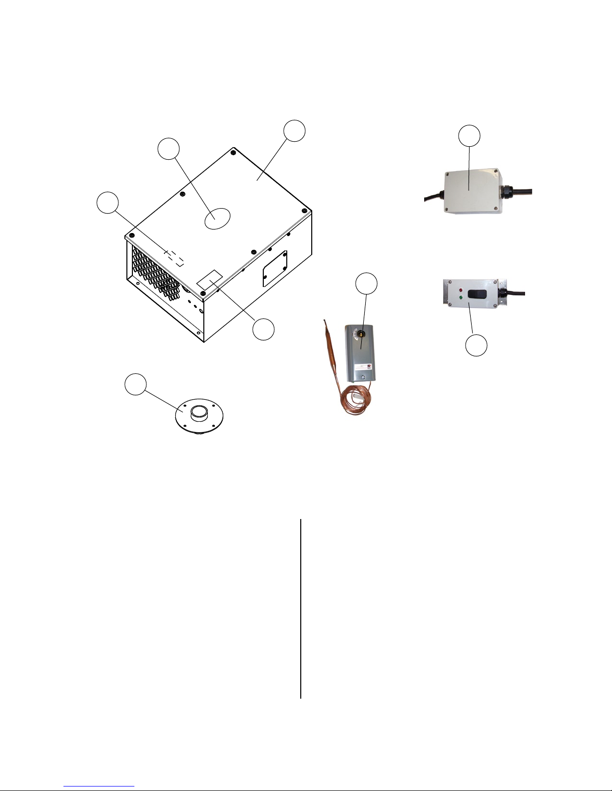
Ref # Name Part #
1 Heater Body see p A2
2 Product of Elston Decal SD-02
3 Serial Number HD-22
Ref # Name Part #
1-9 Universal Heater - 12VDC H-C-1
1-10 Universal Heater - 24VDC H-C-24
1-9,11 Universal Heater -
12VDC w/ Remote
H-C-1R
4 Decal - Voltage &
Pressure Requirements
HD-23
Parts List Complete Unit
A1
10
11
1
2
3
4
5
7
2
4
3
5
6
5 Exhaust Coupling HC-111
8 Owners Manual
(not shown)
HD-27
7 Thermostat HLC-225
9 Mounting Template
(not shown)
HD-28
10 24V Converter Box HC-500
11 Remote Box HC-550
A
B
C
A
B
B
A
A
B
B
A
6 Gasket for HC-111
(not shown)
HC-112
4
Table of contents
Other Elston Manufacturing Heater manuals

Popular Heater manuals by other brands


TPI
TPI FPQ 3310 Series installation instructions

Harvia
Harvia HYB300230S Installation and user instructions

Heatstore
Heatstore HSAC9000X Installation, operation and maintenance instructions

Sawo
Sawo TH2-30Ni2-CNR manual

Harvia
Harvia Type KIP45 Instructions for installation and use

Vitek
Vitek VT-2176 Manual instruction