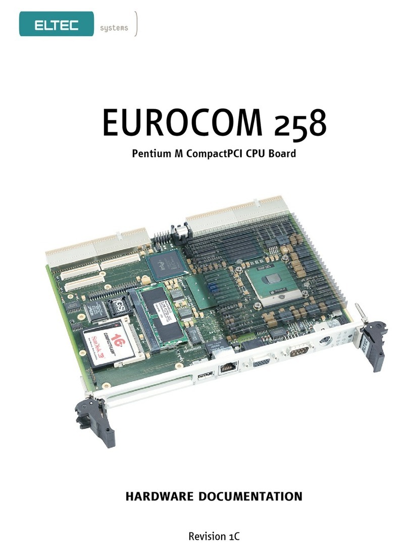
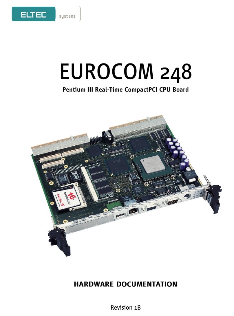
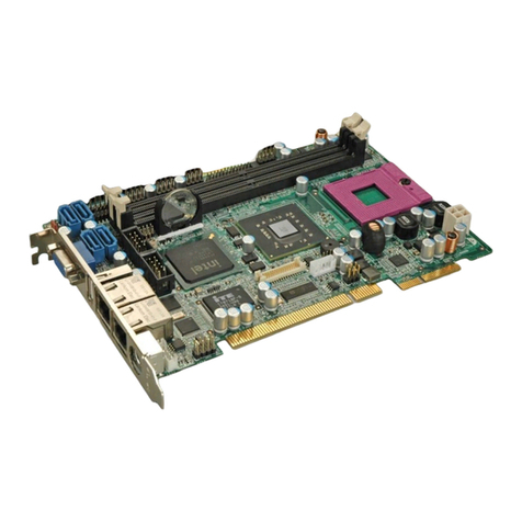
ELTEC EUROCOM 300 Operator's manual

Pentium M-based PCI Real-Time CPU Board
hardware documentation
Revision 0C

Revision
Revision Changes Date / Name
0A First Edition 28.11.05 GM
0B Added Power Consumption 07.02.06 GM
0C Disclaimer new 08.11.06 hh

DISCLAIMER
Copyright
© 2006 ELTEC Elektronik AG. The information, data, and figures in this document including respective references have
been verified and found to be legitimate. In particular in the event of error they may, therefore, be changed at any time
without prior notice. The complete risk inherent in the utilization of this document or in the results of its utilization
shall be with the user; to this end, ELTEC Elektronik AG shall not accept any liability. Regardless of the applicability of
respective copyrights, no portion of this document shall be copied, forwarded or stored in a data reception system or
entered into such systems without the express prior written consent of ELTEC Elektronik AG, regardless of how such acts
are performed and what system is used (electronic, mechanic, photocopying, recording, etc.). All product and company
names are registered trademarks of the respective companies.
Our General Business, Delivery, Offer, and Payment Terms and Conditions shall otherwise apply.
Federal communications commission statement
Þ This device complies with FCC Rules Part 15. Operation is subject to the following two conditions:
Þ This device may not cause harmful interference, and
Þ This device must accept any interference received including interference that may cause undesired operation.
Þ This equipment has been tested and found to comply with the limits for a Class B digital device, pursuant to Part 15
of the FCC Rules. These limits are designed to provide reasonable protection against harmful interference in a
residential installation. This equipment generates, uses and can radiate radio frequency energy and, if not installed
and used in accordance with manufacturer’s instructions, may cause harmful interference to radio communications.
However, there is no guarantee that interference will not occur in a particular installation. If this equipment does
cause harmful interference to radio or television reception, which can be determined by turning the equipment off
and on, the user is encouraged to try correct the interference by one or more of the following measures:
Þ Reorient or relocate the receiving antenna.
Þ Increase the separation between the equipment and receiver.
Þ Connect the equipment to an outlet on a circuit different from that to which the receiver is connected.
Þ Consult the dealer or an experienced radio/TV technician for help.
Þ The us of shielded cables for connection of the monitor to the graphics card is required to assure compliance with
FCC regulations. Changes or modifications to this unit not expressly approved by the party responsible for
compliance could void the user’s authority to operate this equipment.
Canadian department of communications statement
Þ This digital apparatus does not exceed the Class B limits for radio noise emissions from digital apparatus set out in
the Radio Interference Regulations of the Canadian Department of Communications.
Þ This class B digital apparatus complies with Canadian ICES-003
SAFETY INFORMATION
Electrical safety
Þ To prevent electrical shock hazard, disconnect the power cable from the electrical outlet before reloading the
system.
Þ When adding or removing devices to or from the system, ensure that the power cables for the devices are
unplugged before the signal cables are connected. If possible, disconnect all power cables from the existing system
before you add device.
Þ Before connecting or removing signals cables from motherboard, ensure that all power cables are unplugged.

Þ Make sure that your power supply is set to the correct voltage in your area. If you are not sure about the voltage of
the electrical outlet you are using, contact your local power company.
Þ If the power supply is broken, do not try to fix it by yourself. Contact a qualified service technician or your retailer.
Operation safety
Þ Before installing the motherboard and adding devices on it, carefully read the manuals that came with the
package.
Þ Before using the product, make sure all cables are correctly connected and the power cables are not damaged. If
you detect any damage, contact your dealer immediately.
Þ To avoid short circuits, keep paper clips, screws, and staples away from connectors, slots sockets and circuitry.
Þ Avoid dust, humidity, and temperature extremes. Do not place the product in any area where it may become wet.
Þ Place the product on a stable surface.
Þ If you encounter technical problems with the product, contact a qualified service technician or your retailer.
EMC Rules
This unit has to be installed in a shielded housing. If not installed in a properly shielded enclosure, and used in
accordance with the instruction manual, this product may cause radio interference in which case the user may be
required to take adequate measures at his or her own expense.
IMPROTANT INFORMATION
This product is not an end user product. It was developed and manufactured for further processing by trained personnel.
RECYCLING
Please recycle packaging environmentally friendly:
Packaging materials are recyclable. Please do not dispose packaging into domestic waste but recycle it.
Please recycle old or redundant devices environmentally friendly:
Old devices contain valuable recyclable materials that should be reutilized. Therefore please dispose
.... old devices at collection points which are suitable.

I
hardware documentation eurocom 300
table of contents
1. Specification .......................................................................................................1
1.1. Blockdiagram....................................................................................................................1
1.2. Main Features ...................................................................................................................2
1.3. Overview........................................................................................................................... 3
1.3.1. Technical Details..................................................................................................................................... 3
1.3.1.1. CPU ................................................................................................................................................... 3
1.3.1.2. Memory Configuration........................................................................................................................ 3
1.3.1.3. Chip Set ............................................................................................................................................. 3
1.3.1.4. Graphics Interface .............................................................................................................................. 3
1.3.1.5. Boot PROM ........................................................................................................................................ 4
1.3.1.6. Ethernet Interfaces............................................................................................................................. 4
1.3.1.7. Serial I/O ........................................................................................................................................... 4
1.3.1.8. PCISA Interface .................................................................................................................................. 4
1.3.1.9. Timer ................................................................................................................................................. 4
1.3.1.10. Non-volatile Memory.......................................................................................................................... 4
1.3.1.11. Operating Systems ............................................................................................................................. 4
1.3.1.12. Front-panel I/O .................................................................................................................................. 4
1.3.1.13. Board-internal I/O.............................................................................................................................. 5
1.3.1.14. Miscellaneous .................................................................................................................................... 5
1.3.1.15. Industry-grade Case ........................................................................................................................... 5
1.4. Installation .......................................................................................................................6
1.4.1. Introduction ........................................................................................................................................... 6
1.4.2. SO-DIMM Installation.............................................................................................................................. 6
1.4.3. Board Installation ................................................................................................................................... 6
1.4.4. Graphics................................................................................................................................................. 6
1.4.5. Keyboard................................................................................................................................................ 6
1.4.6. Mouse .................................................................................................................................................... 6
1.4.7. Serial ..................................................................................................................................................... 7
1.4.8. Ethernet ................................................................................................................................................. 7
1.4.9. CompactFlash ......................................................................................................................................... 7
1.4.10. USB........................................................................................................................................................ 7
1.4.11. Ethernet Status LEDs............................................................................................................................... 8

II
hardware documentation eurocom 300
1.5. BIOS Setup........................................................................................................................9
1.5.1. Power On Self Test................................................................................................................................ 10
1.5.2. The BIOS User Interface ........................................................................................................................ 10
1.5.3. Setup Screen System..............................................................................................................................12
1.5.3.1. Basic CMOS Configuration Screen......................................................................................................13
1.5.3.2. Features Configuration Setup Screen .................................................................................................16
1.5.3.3. Custom Configuration Setup Screen...................................................................................................18
1.5.4. Drive Settings Examples.........................................................................................................................21
1.5.4.1. Internal Compact flash drive..............................................................................................................21
1.5.4.2. Hard Disk..........................................................................................................................................22
1.5.4.3. Booting from CD ROM.......................................................................................................................23
1.5.4.4. Booting from USB .............................................................................................................................24
1.5.5. Console Redirection ...............................................................................................................................25
1.5.6. EMBEDDED BIOS POST Codes.................................................................................................................25
1.5.7. Critical Error Beep Codes ...................................................................................................................... 28
1.6. Intel Boot Agent / PXE ..................................................................................................... 29
1.6.1 Boot Agent Setup............................................................................................................. 29
1.6.2 Setup Screen options ....................................................................................................... 29
1.6.1. Diagnostics Information.........................................................................................................................31
1.7. Cooling Requirements ..................................................................................................... 32
1.8. Testing the Installation.................................................................................................... 32
2. Interface Connectors .........................................................................................33
2.1. Mainboard .......................................................................................................................33
2.2. PCISA Connector ............................................................................................................. 34
2.3. LAN .................................................................................................................................35
2.4. Miscellaneous I/O ............................................................................................................ 37
2.5. COM1 and COM2 ............................................................................................................. 38
2.6. VGA ................................................................................................................................ 39
2.7. Keyboard / Mouse............................................................................................................ 40
2.8. USB ................................................................................................................................ 41
2.9. IDE ................................................................................................................................. 42

III
hardware documentation eurocom 300
3. Board Parameters..............................................................................................43
3.1. Host Bus ......................................................................................................................... 43
3.2. PCISA Bus .......................................................................................................................43
3.3. Memory ..........................................................................................................................43
3.4. PCI Local Bus .................................................................................................................. 43
3.5. Network .......................................................................................................................... 43
3.6. Serial.............................................................................................................................. 43
3.7. USB ................................................................................................................................ 43
3.8. Keyboard ........................................................................................................................44
3.9. Mouse............................................................................................................................. 44
3.10. Video I/O ........................................................................................................................ 44
3.11. MTBF Values ................................................................................................................... 45
3.12. Environmental Conditions................................................................................................ 45
3.13. Power Requirements........................................................................................................ 45
3.14. Battery............................................................................................................................ 45
4. Programmers Reference.....................................................................................46
4.1. Hex Switch ......................................................................................................................46
4.2. UserLED .......................................................................................................................... 46
4.2.1. UserLED 1............................................................................................................................................. 46
4.2.2. UserLED 2............................................................................................................................................. 46
4.2.3. Example ................................................................................................................................................47
4.3. NVRAM ...........................................................................................................................47
4.4. Interrupts........................................................................................................................ 48

IV
hardware documentation eurocom 300
list of table
Table 1.1: Speed LED.................................................................................................................................................... 8
Table 1.2: Link / Activity LED ........................................................................................................................................ 8
Table 2.1: PCISA Connector .........................................................................................................................................34
Table 2.2: Pinout LAN1 X1001......................................................................................................................................35
Table 2.3: Pinout LAN2 X1101 ......................................................................................................................................36
Table 2.4: Pinout X807 ................................................................................................................................................37
Table 2.5: Pinout COM1 and COM2 Connectors X803 and X804 .....................................................................................38
Table 2.6: Pinout VGA Connector X801 ........................................................................................................................39
Table 2.7: Pinout Keyboard / Mouse Connector X802................................................................................................... 40
Table 2.8: Pinout USB1 X805 .......................................................................................................................................41
Table 2.9: Pinout USB2 X806.......................................................................................................................................41
Table 2.10: Pinout IDE Connector ................................................................................................................................42
Table 4.1: UserLED 1 Register SuperIO + Offset 0x5D .................................................................................................. 46
Table 4.2: UserLED 2 Register SuperIO + Offset 0x5E .................................................................................................. 46

V
hardware documentation eurocom 300
list of figures
Figure 1.1: Blockdiagram ............................................................................................................................................. 1
Figure 1.2: Location Ethernet Status LEDs ..................................................................................................................... 8
Figure 1.3: Location of Clear CMOS Jumper................................................................................................................... 9
Figure 1.4: The text-based system, BIOS POST, provides a familiar desktop PC look-and-feel. .......................................10
Figure 1.5: The graphical POST provides an instant-on and controlled display for the user to view. ...............................11
Figure 1.6: The Embedded BIOS Setup Screen Menu allows access to configuration and embedded features..................12
Figure 1.7: The Embedded BIOS Basic Setup Screen is used to configure drives, boot actions, and POST. ......................13
Figure 1.8: The Feature Configuration Setup Screen.....................................................................................................16
Figure 1.9: The BIOS Custom Setup Screen is used to configure low-level hardware. .....................................................18
Figure 1.10: The Basic Configuration Screen for Compact flash.....................................................................................21
Figure 1.11: The Basic Configuration Screen for IDE Hard Disk .....................................................................................22
Figure 1.12: The Basic Configuration Screen for CDROM Boot.......................................................................................23
Figure 1.13: The Basic Configuration Screen for USB Boot............................................................................................24
Figure 1.14: Teh Feature Configuration Screen for USB Boot ........................................................................................24
Figure 1.15: Intel Boot Agent Setup Screen ................................................................................................................. 29
Figure 1.16: Setup Screen with Diagnostic Messages ....................................................................................................31
Figure 2.1: Location of Connectors on Mainboard.........................................................................................................33
Figure 2.2: LAN1 Connector.........................................................................................................................................35
Figure 2.3: LAN2 Connector.........................................................................................................................................36
Figure 2.4: X807 Connector .........................................................................................................................................37
Figure 2.5: COM1 and COM2 Connector .......................................................................................................................38
Figure 2.6: VGA Connector X801..................................................................................................................................39
Figure 2.7: Keyboard / Mouse Connector X802 ............................................................................................................ 40
Figure 2.8: Connector USB1 X805 ................................................................................................................................41
Figure 2.9: Connector USB2 X806................................................................................................................................41
Figure 2.10: Connector IDE..........................................................................................................................................42
Figure 3.1: Resolution Table ........................................................................................................................................44
Figure 4.1: Interrupt Routing Scheme ......................................................................................................................... 48

1
hardware documentation eurocom 300
1. Specification
1.1. Blockdiagram
Pentium/Celeron M
On-chip
Cache 1 / 2 MB
BIOS
Flash EPROM
Peripharals
2* Serial USB
Main Memory
SODIMM
Chip Set
I855GME
with Graphics
PCI Connector (PCISA)
Ethernet
1 Gbps
PCI bus
ISA/LPC bus
Compact Flash socket
& Harddisk
Non-volatile Memory
512 kB
Ethernet
1 Gbps
Figure 1.1: Blockdiagram

2
hardware documentation eurocom 300
1.2. Main Features
Þ Pentium M-based PCISA CPU board up to 2.1 GHz (1.8 GHz with CPUs from Intel embedded program)
Þ Intel 855GME chip set
Þ Up to 1024 MB SDRAM on SO-DIMM
Þ PCI local bus, 32-bit, 33 MHz
Þ Dual 10/100 Mbps network interface, Gigabit optional
Þ Two serial channels
Þ 512 KB fast non-volatile RAM for process data
Þ IDE hard disk controller with On-board CompactFlash connector and two other ATA drives
Þ PCISA (PISA) format with PCI interface
Þ USB 2.0
Þ Keyboard and Mouse interface
Þ On-board Graphics

3
hardware documentation eurocom 300
1.3. Overview
1.3.1. Technical Details
The EUROCOM 300 is an Intel Pentium M single-board computer with PCISA (PISA) interface, optimized
for real-time applications, while maintaining full PC compatibility. This is the ideal platform for industrial
applications with real-time operating systems, extending ELTEC's successful BAB product line for Intel
CPUs.
1.3.1.1. CPU
A Pentium M or Celeron M CPU is supported: the board is compatible with the Banias or Dothan versions
of this embedded CPU; CPU clocks between 1.3 and 1.8 GHz are supported. The CPU has FPU, MMU,
first level cache (32 KB each for instruction and data) and a L2 cache (1 MB unified) on the chip. It
contains dual integer units, that can operate in parallel for certain instructions; the floating point unit is
optimized for fast single precision multiply-add operations. Special care has been taken to achieve a low
power consumption and a good relationship between clock and computing performance: the Pentium M
CPU generally achieve the same performance as a Pentium 4 with a clock that is by a factor 1.4 higher.
The second-level cache, due to its location in the CPU itself, runs with the full CPU clock.
CPU Pentium M Celeron M
L1 cache (Instr/Data) 32/32 KB 32/32 KB
L2 cache 2 MB on-chip 1 MB on-chip
Bus speed (FSB) 400 MHz 400 MHz
CPU core Dothan Dothan
Speedstep x -
CPU speed 1.8 GHz 1.5 GHz
Power consumption 21 W 22 W
The low power consumption of the CPU makes it possible to build systems withstanding high ambient
temperatures with simple cooling.
1.3.1.2. Memory Configuration
The 64-bit wide memory allows configurations of up to 1024 MBytes with DDR RAMs in a single SO-DIMM
module.
1.3.1.3. Chip Set
The chip set, an i855GME, contains the DDR RAM memory controller, the interrupt controller, and the
PCI host bridge for 32-bit/33-MHz PCI. Additionally, it has logic to access an BIOS ROM, it has timers, a
DMA controller, and it generates clocks.
1.3.1.4. Graphics Interface
The chip set-internal graphics controller is AGP-based; it uses up to 64 MB of main memory. Maximum
display resolution is 2048 * 1536 * 75 Hz @32 bit/pixel.

4
hardware documentation eurocom 300
1.3.1.5. Boot PROM
Boot code is stored in a Flash EPROM (size 512 KB) which enables easy code updates. The boot proms
contains the BIOS, an embedded version from General Software with PXE netboot.
1.3.1.6. Ethernet Interfaces
The dual network interfaces use Ethernet controllers i82559 ER for 10/100 Mbps transfers with 10BaseT
(twisted pair) or 100Base TX connectivity. As an option, Gigabit Ethernet controllers i82541 are supplied
for 10/100/1000 Base TX functionality.
Automatic speed detection is included. A Link LED and an Activity LED allow an easy first check if the
Ethernet connection works.
1.3.1.7. Serial I/O
Two asynchronous serial channels (chip set-internal) with up to 115 kbaud transfer rate and 16-byte FIFO
with RS232 levels are available.
1.3.1.8. PCISA Interface
The PCISA/PISA interface is implemented with system slot capabilities for 32-bit PCI systems. It features
transfer rates of up to 128 MByte/s between board-internal resources and PCISA devices. The PCISA
interface uses only the PCI bus signals.
The board must occupy the PCI system slot and it will set up all PCI peripherals on the PCI back plane.
The board can drive PCI buses (passive back planes) with up to 4 peripheral slots, all of them can obtain
bus mastership (DMA).
1.3.1.9. Timer
The EUROCOM 300 has three standard PC programmable timers for timing interrupts in the 1 us to 1000
ms range.
1.3.1.10. Non-volatile Memory
Besides the normal RTC-based non-volatile memory, an additional user memory is present (optional).
User memory (512 KB) is implemented in a non-volatile RAM using a combination of SRAM, used when
the system is running, and an EEPROM, that is automatically programmed with SRAM data during
power-down and that supplies SRAM data during power-up. Data read/write rate is 10 MB/s.
1.3.1.11. Operating Systems
As a Pentium M-based CPU board with a complete BIOS, the EUROCOM 300 can of course be run
under Windows.
Compliant with the ELTEC Linux Initiative, the EUROCOM 300 additionally supports implementations of
Standard Linux and ElinOS - applications for both operating systems can be designed under Linux. Linux
is best when a full operating system is needed. ELinOS is for embedded applications with the smallest
footprint.
1.3.1.12. Front-panel I/O
The four front-panel connectors carry the I/O signals for network and serial (2 * serial and 2* 100BaseTx)
as one option. In another product option for PC-compatible use, VGA, Ethernet (RJ45) and keyboard/mouse are routed to
the panel.

5
hardware documentation eurocom 300
1.3.1.13. Board-internal I/O
The board has additional on-board connectors for use with cables to user-supplied front panels respectively. internal
use: IDE (UDMA5 for 2 disks), VGA, keyboard, mouse, serial (* 2), USB (*4), speaker, IrDA, AC97 sound, LEDs.
1.3.1.14. Miscellaneous
Through the PCISA connector up to four external PCI slots are supported. If more than 4 external slots are needed, a
back plane with an integrated PCI-PCI bridge must be used.
1.3.1.15. Industry-grade Case
As an option, the EUROCOM 300 can be ordered in an industrial-grade case, made of stainless steel. This case has a
passive PCISA back plane with four free PCI slots; it has a power supply with sufficient cooling fans for the EUROCOM
300 and the peripheral boards.

6
hardware documentation eurocom 300
1.4. Installation
1.4.1. Introduction
Do always observe precautions for handling electrostatic devices when unplugging boards from the rack or otherwise
handling boards. Avoid touching integrated circuits except in an electrostatic free environment. Electrostatic discharge
can damage circuits or shorten their lifetime.
Þ Carefully remove the board from the shipping carton.
Þ Save the original shipping container and packing material for storing or reshipping the board.
Þ Inspect the board for any shipping damage. If undamaged, the board can be prepared for system installation.
1.4.2. SO-DIMM Installation
If the EUROCOM 300 is not shipped with DRAM SO-DIMMs, the user must insert his own SO-DIMMs (PC2100 or PC2700)
on the board. The EUROCOM 300 is not able to run without DRAM. SO-DIMM installation can be done easily. The board
has one SO-DIMM socket, X201. The BIOS software detects automatically if the bank is populated. Also the size of the
DIMMs is detected automatically. The SO-DIMM is simply plugged into the socket (it fits only in one orientation). The
two metal latches on the socket must hold the SODIMM. Otherwise the SO-DIMM is not properly connected.
1.4.3. Board Installation
All add-on modules on the EUROCOM 300 are already installed when shipped. There is no reason to remove add-on
modules. The EUROCOM 300 requires a PCISA backplane. After the board was plugged into the backplane, the front
panel can be fixed with a screw in the rack. Additionally a card holder should be used that prevents the board from
sliding out of the PCISA connector (case specific). Make sure that the power supply within the rack meets the power
requirements specified in Section "Power Requirements". Also the operating requirements must meet the values
specified in Section "Environmental Conditions".
Caution:
Due to the low power consumption during power up, the board is not able to comply with the minimal power
consumption for an ATX Power Supply older than Version V1.2 (less than 1A on +5V Power Rail). Therefore it is
important to have additional load (like Harddisk or Floppy) to fulfil this condition when using an ATX (Power
Supply).
1.4.4. Graphics
If a CRT monitor is used, a standard VGA cable (15 pins) is connected between the monitor and connector X801 of the
board (the board is normally equipped with a small adapter module that converts X801 to a standard VGA connector).
Make sure that your monitor is capable of displaying higher video resolutions. If a video mode generates horizontal
frequencies much higher than the maximum value of your monitor, the monitor may be damaged! If your monitor is not
able to display a mode, switch off or disconnect the monitor in advance and select an appropriate video mode for the
monitor.
1.4.5. Keyboard
A standard PS/2 keyboard can be connected to X802 via a small adapter module. If an AT keyboard is desired, cable
adapter ADAP-210 can be used. A PS/2 keyboard can be connected directly.
1.4.6. Mouse
A standard PS/2 mouse can be connected to the X802 connector using a split adapter.

7
hardware documentation eurocom 300
1.4.7. Serial
Serial devices can be connected to X803 (COM2) and X804 (COM1) via appropriate cable. The pinout of X803 and X804 is
such that a cable could be made of a 10pin IDC connector and a 9pin MIN-D connector. The interface supports speed up
to 115200 kb/s.
1.4.8. Ethernet
A Network can be connect using 10BaseT, 100BaseTX or 1000BaseT standard. It can be connected to X1001 / X1101.
1.4.9. CompactFlash
A CompactFlash-Card Typ 1 can be installed in the socket X503. The card is mapped as an IDE-Drive into the system. It
will be the Master device of the primary IDE-Channel. Note that hot plugging is not allowed because the BIOS needs to
find the CF-Card at startup for proper operation.
1.4.10. USB
Up to four USB devices can be connected to X805 and X806 via appropriate adapters. If the adapter has 1 x 4 or 1 x 5
connectors make sure that the red wire (positive supply) is connected to pin 1 or 2 of X805 or X806.

8
hardware documentation eurocom 300
1.4.11. Ethernet Status LEDs
Link/Activit
y
Speed
Figure 1.2: Location Ethernet Status LEDs
Table 1.1: Speed LED
green 1000Mb/s
yellow 100Mb/s
off 10Mb/s or not active
Table 1.2: Link / Activity LED
yellow linkpulse detected
blinking Activity

9
hardware documentation eurocom 300
1.5. BIOS Setup
The EUROCOM 300 is delivered with an EMBEDDED BIOS from GENERAL SOFTWARE. The BIOS includes a setup menu to
configure basic settings. ELTEC ships the EUROCOM 300 with optimized BIOS settings. If desired, most of the BIOS
settings can be changed (some settings are hardwired). Also if the battery for the CMOS RAM is weak, the RAM may
loose its contents making a new setting of the setup necessary. Caution should be taken because some changes of
settings may cause an erroneous system behaviour.
It may happen that the values in the nonvolatile memory inhibit starting of the EUROCOM 300. In this case the RUN
LED will light for a short time when the board is reset and then stays dark. The board can be reset to the default values
by the following procedure:
Þ remove the board from the rack
Þ momentary shortcut the two pads marked in Figure Location of Clear CMOS Jumper
Þ reinstall board
Figure 1.3: Location of Clear CMOS Jumper

10
hardware documentation eurocom 300
1.5.1. Power On Self Test
When the EUROCOM 300 is powered on, the BIOS tests and initializes the hardware and programs the chipset and other
peripheral components. During this time, Power On Self Test (POST) progress codes are written by the system BIOS to
I/O port 80h, allowing the user to monitor the progress with a special monitor. A later chapter lists the POST codes and
their meanings.
During early POST, no video is available to display error messages should a critical error be encountered; therefore,
POST uses beeps on the speaker to indicate the failure of a critical system component during this time. A later chapter
lists the Beep codes and their meanings.
1.5.2. The BIOS User Interface
The EUROCOM 300 can use the standard keyboard and video device, or use console redirection to demonstrate headless
operation. If an RS232 cable is attached to COM1, a PC/AT-style character-based POST is available from HyperTerminal,
PROCOMM, or any other terminal emulator software that supports VT100 emulation.
When a keyboard and video device are attached, the EUROCOM 300 can display either a traditional character-based PC
BIOS display with memory count-up, or it can display a graphical POST with splash screen and progress icons. Both
POST displays accept a <DEL> key press to enter the setup screen, and both display boot-time progress activity displays.
The graphical display shows the status of file system devices and even OEM-defined devices (when the OEM adapts the
BIOS to a particular OEM platform), but omits character-based PCI resource display. The text-based POST displays the
memory count-up and the PCI resource assignment table.
The following figure shows the format of the text-based POST display. The display is very similar if console redirection
through a COM port is used instead.
General Software Embedded BIOS(R) 2000 Revision 5.3
Intel Pentium M 1500 MHz, Eltec E300 BIOS Version 1.C
00000598K Low Memory Passed
00086976K Ext Memory Passed
Hit <Del> if you want to run SETUP.
Figure 1.4: The text-based system, BIOS POST, provides a familiar desktop PC look-and-feel.

11
hardware documentation eurocom 300
The next figure shows the graphical version of POST. The BIOS decompresses the main image, and can display multiple
overlaid graphics at various points in POST. The OEM can define the entire sequence and control the timing of the
system for an embedded application, and can arrange to have different graphics displayed on each successive boot of
the system. This feature is ideal for embedded systems that must show evidence of operation during startup, while the
application loads underneath the splash screen. Once the application begins writing to the screen, the splash screen
relinquishes control, providing a seamless graphical progression for the end user.
Figure 1.5: The graphical POST provides an instant-on and controlled display for the user to view.
When the EUROCOM 300 is powered on for the first time, you’ll need to configure the system through the Setup Screen
System (described later) before peripherals, such as disk drives, are recognized by the BIOS. The information is written
to battery-backed CMOS RAM on the board’s Real Time Clock. Should the board’s battery fail, this information will be
lost and the board will need to be reconfigured.
The EUROCOM 300 Basic Setup Screen provides an option to disable the graphical POST and switch to the legacy text-
based version. This feature may not permanently disable the graphical POST if the BIOS adaptation calls for reverting to
the graphical form after so many boots. If you find that the graphical POST comes back after several boots, it is because
this option is enabled for this platform. Naturally, the OEM can use the Embedded BIOS Adaptation Kit to control
whether Setup can be used to dictate the policy, and whether it is permanent or temporary
Table of contents
Other ELTEC Computer Hardware manuals
Popular Computer Hardware manuals by other brands

Panasonic
Panasonic SH-AC300 operating instructions

Sun Microsystems
Sun Microsystems Fire 6800 installation guide

Roland
Roland MV-8800 Production Studio user manual

InFocus
InFocus SP-CWRS232 Product note
Adaptec
Adaptec 2940U2W - Storage Controller U2W SCSI 80... installation guide

Parker
Parker Compumotor OEM350 user guide

Huawei
Huawei SDongleA-03 quick guide
Delta Electronics
Delta Electronics IPM- C Series Specification sheet
Delta Tau
Delta Tau 24E2A user manual
Delta Electronics
Delta Electronics TDHCB Specifications

Z3 Technology
Z3 Technology FSDI-13A-RPS user guide
Renesas
Renesas IAR KickStart Kit R-IN32M4-CL3 user manual

