Premium Supply RoaDCharger 20 Amp 7 Way User manual

RoaDCharger 20 Amp 7 Way Installation Manual

1
Safety First
This symbol is used to call attention to instructions concerning personal safety. Be
sure to observe and follow these instructions. Take time to be careful!
WARNING indicates a potentially hazardous situation which, if not
avoided, COULD result in death or serious injury and includes hazards that are exposed
when guards are removed.
WARNING
BATTERIES
• To avoid injury, eye protection and acid-resistant gloves must be worn when working around batteries.
Do not smoke, use open flame, make sparks or create other ignition sources around batteries. If a battery
is giving off gases, it can explode and cause injury to personnel. Remove all jewelry such as rings, ID
tags, watches, and bracelets. If jewelry or a tool contacts a battery terminal, a direct short will result in
instant heating or electric shock, damage to equipment, and injury to personnel.
• Sulfuric acid contained in batteries can cause serious burns. If battery corrosion or electrolyte makes
contact with skin, eyes or clothing, take immediate action to stop the corrosive burning effects. Failure to
follow these procedures may result in injury or death.
a. Eyes. Flush with cold water for no less than 15 minutes and seek medical attention immediately.
b. Skin. Flush with large amounts of cold water until all acid is removed. Seek medical attention as
required.
c. Internal. If corrosion or electrolyte is ingested, drink large amounts of water or milk. Follow with milk of
magnesia, beaten egg or vegetable oil. Seek medical attention immediately.
d. Clothing/Equipment. Wash area with large amounts of cold water. Neutralize acid with baking soda or
household ammonia.
• To minimize risk of fire or explosion, follow these battery servicing safety
precautions:
• Never check battery charge by placing a metal object across the
battery posts. A spark will occur and cause possible explosion. Use a
voltmeter or hydrometer.

Introduction: Congratulations on your new RoaDCharger! This device is going to help
keep your trailer battery within its peak performance parameters, which will allow you greater
productivity and lower cost of ownership. In this manual, we will cover the basic installation
procedure, as well as some key tips for before and after your installation. Lets Get Started!
Pre Installation Checklist: With this checklist, we are creating a baseline for
functionality of the electrical circuits on the trailer. If any of these functions do not work, please
stop work immediately and address the problem before moving forward with installation.
NOTE: If you have no 12 volt accessory power at 7-way please reference vehicle manual for
more information.
Electrical System Functions
Brake Lights Yes___ No___
Left Turn Signal Yes___ No___
Right Turn Signal Yes___ No___
Tail / Running Lights Yes___ No___
Electric Brakes Yes___ No___
Breakaway System Yes___ No___
12 Volts At 7-Way Yes___ No__

RoaDCharger Installation:
Please follow the steps below and the diagrams / notes on the next few pages to
ensure the RoaDCharger is installed properly.
1) First, remove the unit from the packaging and inspect for any damage
during shipping (report immediately if there is damage).
2) Next, find a suitable place to mount the unit using the four 5/16” holes for
mounting. It is rated for exterior mounting so feel free to install on outside
wall of toolbox, front, sides, or rear wall if there is room. Ensure nothing
will impact the units during normal operation of the trailer (dump bed, tow
vehicle, jack handle, etc).
oNOTE: Be sure to consider length of charging wires (Blue, Yellow,
and Black) when deciding on mounting location. These wires are
NOT to be cut and extended.
3) Drill four holes in box and install using bolts supplied by you, the
installer.
4) Once unit is mounted firmly to toolbox, locate area in bottom of toolbox
to drill 5/8” hole to pass charging wires through. In some toolboxes there are
holes suitable to pass wires through already in existence. If this is the case
then utilize.
5) Pass charging wires through hole in box (see previous step) and attach to
battery.
oNOTE: BLUE and YELLOW attach to the POSITIVE terminal.
BLACK attaches to NEGATIVE terminal.
6) At this point unit should be mounted, and charging wires connected to
trailer battery.

7) Now take the male 7-way from the trailer and insert it into the 7-way
female provided on the RoaDCharger.
8) Take the male 7-way that is provided with the RoaDCharger and route it
through the tongue of the trailer to near the hitch. This will plug into vehicle
7-way.
9) Perform Post Installation Checks.
10) Sit Back, Relax, and let the RoaDCharger do its job!

Post Installation Checklist: This checklist ensures functionality of the electrical
circuits on the trailer have not been affected during the installation. If any of these functions do
not work, please stop work immediately and address the problem before moving forward with
installation.
Electrical System Functions
Brake Lights Yes___ No___
Left Turn Signal Yes___ No___
Right Turn Signal Yes___ No___
Tail / Running Lights Yes___ No___
Electric Brakes Yes___ No___
Breakaway System Yes___ No___
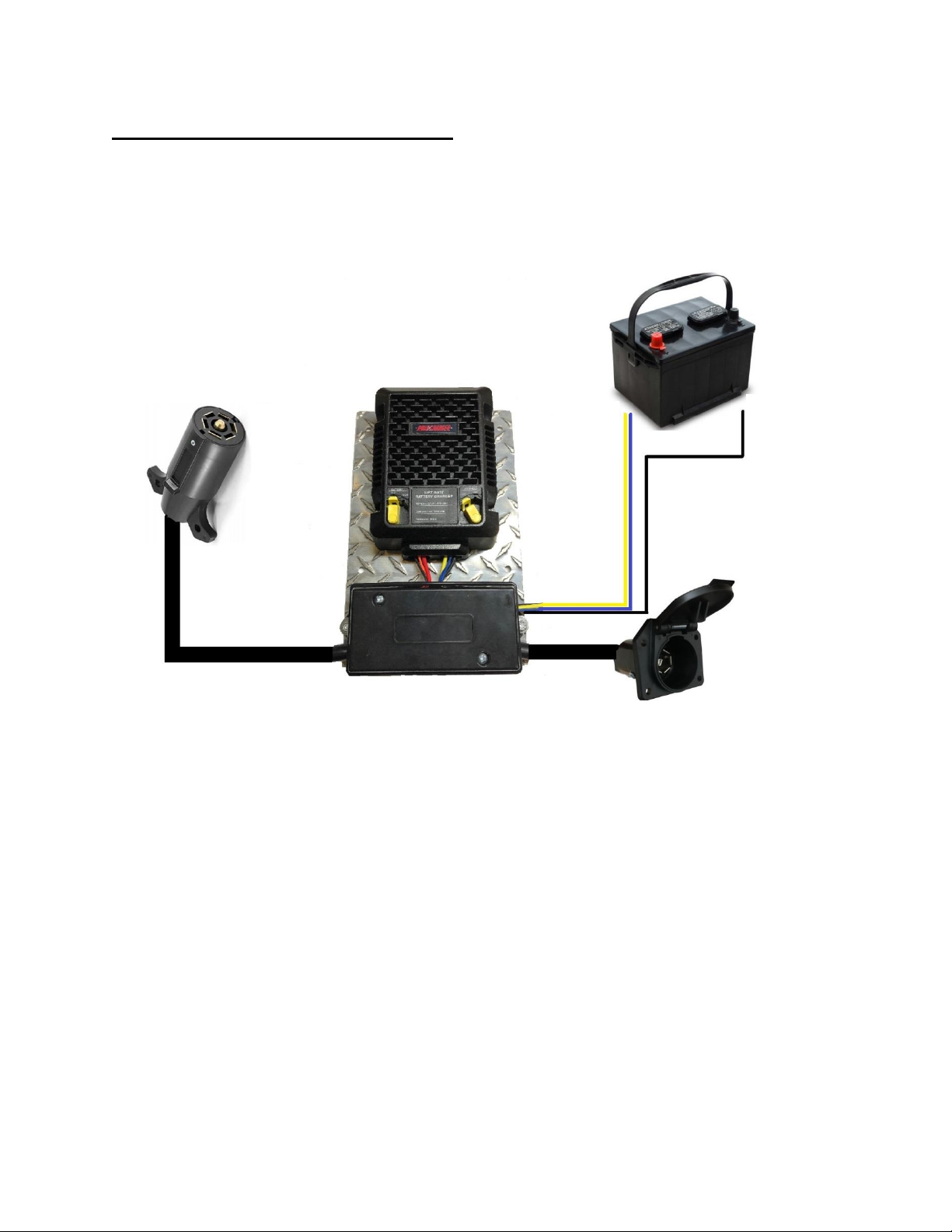
RoaDCharger Wiring Diagram:
+
Connect To Vehicle 7 Way
-
Connect To Trailer 7 Way

Post Installation Notes:
Local LED indicators:
Power status/Standby Indicator (Blue LED): Solid ON while charging, OFF when the input
voltage is too low either because of too much draw on the battery or the truck has been turned
off. It will also flash 100ms ON, 3 seconds off when it is Extended charging mode and the input
voltage is between 12.5v and 12.7v during input voltage inspection periods.
Diagnostic/Failure Indicator (Red/Green LED): This LED will blink based on failures below.
Should be reported as an error code then 10s delay, then error code again.
Blink Code
Indication
1 Red Blink
Internal temperature is too high, will reduce
output current until it has cooled down
2 Red Blink
Input voltage is too low, output will shut off
3 Red Blink
Input or output voltage is too high
4 Red Blink
Output over current/output shorted to ground
5 Red Blink
External temperature sensor has failed
6 Red Blink
Internal temperature sensor has failed
1 Amber Blink
Input voltage is getting low and causing less than
maximum output current
Charging Mode (Blue LED):
a. Sold ON: Bulk Charging Stage
b. Rapid Flash: Absorption stage
c. Slow Flash: Float Stage
Front Panel Selector Switches:
Battery Type: Selector switch on the unit ensures optimal charge
profile for AGM or flooded lead acid batteries. Make selection of type of battery you are
charging.
Extender: Selector switch on the unit enables battery charging after
the engine is off, while maintaining starting capability. Choose “On”, to use this option or “Off”
to shut down unit when vehicle is turned off.
WARRANTY -1-year warranty for defects in material and workmanship
Wire Color
Function
Connect to
Black
Ground
Vehicle ground
Yellow
Charger Output
Charging Batteries
Blue to battery lug
Battery Temp Sensor
Positive trailer battery terminal
Table of contents


