ELTEX SCC-P User manual
Operating Instructions
Static Combi Cleaner SCC-P
BA-en-2087-2207
Z-118074y_1

2BA-en-2087-2207_Static Combi Cleaner SCC-P

BA-en-2087-2207_Static Combi Cleaner SCC_P 3
List of contents
1 Outline of appliance . . . . . . . . . . . . . . . . . . . . . . . . . . . . . . . . . . . 7
2 Safety . . . . . . . . . . . . . . . . . . . . . . . . . . . . . . . . . . . . . . . . . . . . . . . 8
2.1 Identification of risks and hazards . . . . . . . . . . . . . . . . . . . . . . . . . 8
2.2 Contact protection . . . . . . . . . . . . . . . . . . . . . . . . . . . . . . . . . . . . . . 8
2.3 Inspection of the protective resistors - contact protection . . . . . . . . 8
2.4 Technical advance . . . . . . . . . . . . . . . . . . . . . . . . . . . . . . . . . . . . . 9
2.5 Proper use . . . . . . . . . . . . . . . . . . . . . . . . . . . . . . . . . . . . . . . . . . . 9
2.6 Work and operational safety. . . . . . . . . . . . . . . . . . . . . . . . . . . . . 10
3 Installation and Assembly . . . . . . . . . . . . . . . . . . . . . . . . . . . . . 12
3.1 Installation . . . . . . . . . . . . . . . . . . . . . . . . . . . . . . . . . . . . . . . . . . . 12
3.2 Connecting the suction line . . . . . . . . . . . . . . . . . . . . . . . . . . . . . . 13
3.3 Adjusting the suction line . . . . . . . . . . . . . . . . . . . . . . . . . . . . . . . . 13
3.4 Connecting the high voltage cable to the ion blower nozzle. . . . . . 14
3.5 Connecting the high voltage cable to the power supplies of
series ES5x, ES6x and PI . . . . . . . . . . . . . . . . . . . . . . . . . . . . . . 14
3.6 Connectiong to ground . . . . . . . . . . . . . . . . . . . . . . . . . . . . . . . . . 14
3.7 Routing the high voltage cable . . . . . . . . . . . . . . . . . . . . . . . . . . . . 15
3.8 Connecting the compressed air . . . . . . . . . . . . . . . . . . . . . . . . . . . 15
3.9 Routing the air hose . . . . . . . . . . . . . . . . . . . . . . . . . . . . . . . . . . . . 15
3.10 Compressed air properties . . . . . . . . . . . . . . . . . . . . . . . . . . . . . . . 15
3.11 Impact of heat radiation . . . . . . . . . . . . . . . . . . . . . . . . . . . . . . . . . 15
4 Operation . . . . . . . . . . . . . . . . . . . . . . . . . . . . . . . . . . . . . . . . . . . 16
4.1 Startup . . . . . . . . . . . . . . . . . . . . . . . . . . . . . . . . . . . . . . . . . . . . . . 16
4.2 Operating voltage . . . . . . . . . . . . . . . . . . . . . . . . . . . . . . . . . . . . . . 16
4.3 Function control . . . . . . . . . . . . . . . . . . . . . . . . . . . . . . . . . . . . . . . 16
5 Maintenance . . . . . . . . . . . . . . . . . . . . . . . . . . . . . . . . . . . . . . . . . 17
5.1 Cleaning . . . . . . . . . . . . . . . . . . . . . . . . . . . . . . . . . . . . . . . . . . . . . 17
5.2 Inspection of the protective resistors - contact protection . . . . . . . 18
6 Troubleshooting . . . . . . . . . . . . . . . . . . . . . . . . . . . . . . . . . . . . . 19
7 Technical specifications . . . . . . . . . . . . . . . . . . . . . . . . . . . . . . . 20
8 Dimensions . . . . . . . . . . . . . . . . . . . . . . . . . . . . . . . . . . . . . . . . . 21
Declaration of Conformity . . . . . . . . . . . . . . . . . . . . . . . . . . . . . . . . . . 23

4BA-en-2087-2207_Static Combi Cleaner SCC-P

BA-en-2087-2207_Static Combi Cleaner SCC_P 5
Verehrter Kunde
The Static Combi Cleaner SCC is a high-power ionization cleaning station
for the non-contacting removal of dust and dirt deposits on three-dimen-
sional or structured surfaces.
Static dust is discharged and blown off by a rotating nozzle with two air out-
lets. The rotation creates a pulsating effect on the surface. The nozzle dia-
meter and the angle of the air jets can be adjusted independently of each
other.
The effective elimination of static charges from cleaned surfaces prevents
dust from settling back on product surfaces. The cleaning unit with concen-
tric suction flow is designed for integration into flowing manufacturing pro-
cesses; a relative movement between the component and the SCC-P is
required for the desired cleaning effect.
Applications
• Electronics manufacturing
• Precision mechanics and optical industry
• Surface finishing
• Plastics industry
• Wood processing
Benefits in production
• Improved, consistent quality
• Higher productivity
• No reworkig
• Non-contact, dry cleaning process
Engineering
• Optimised flow guidance, saves compressed air and extraction air
volume
• Integrated discharge technology for perfect discharging performance and
ultimate safety
• Long range
• Robust design
• Facilitated integration into production lines
• Easy installation
• Compact construction
• Adaptable for smallest areas from 20 x 20 mm to 60 x 60 mm
• Ionenbalance in Verbindung mit POWER IONIZER anpassbar
• Shortenable apron for distance adjustment
• Bracket can be mounted in three positions
• Dischargeable enclosure
• Integrated speed monitoring, optional

6BA-en-2087-2207_Static Combi Cleaner SCC-P
Please read the operating instructions carefully before starting the instru-
ment. This will help you prevent personal injuries and damage to property.
Please give us a call if you have any suggestions, proposals or ideas for
improvements. We greatly appreciate the feedback from the users of our
appliances.

BA-en-2087-2207_Static Combi Cleaner SCC_P 7
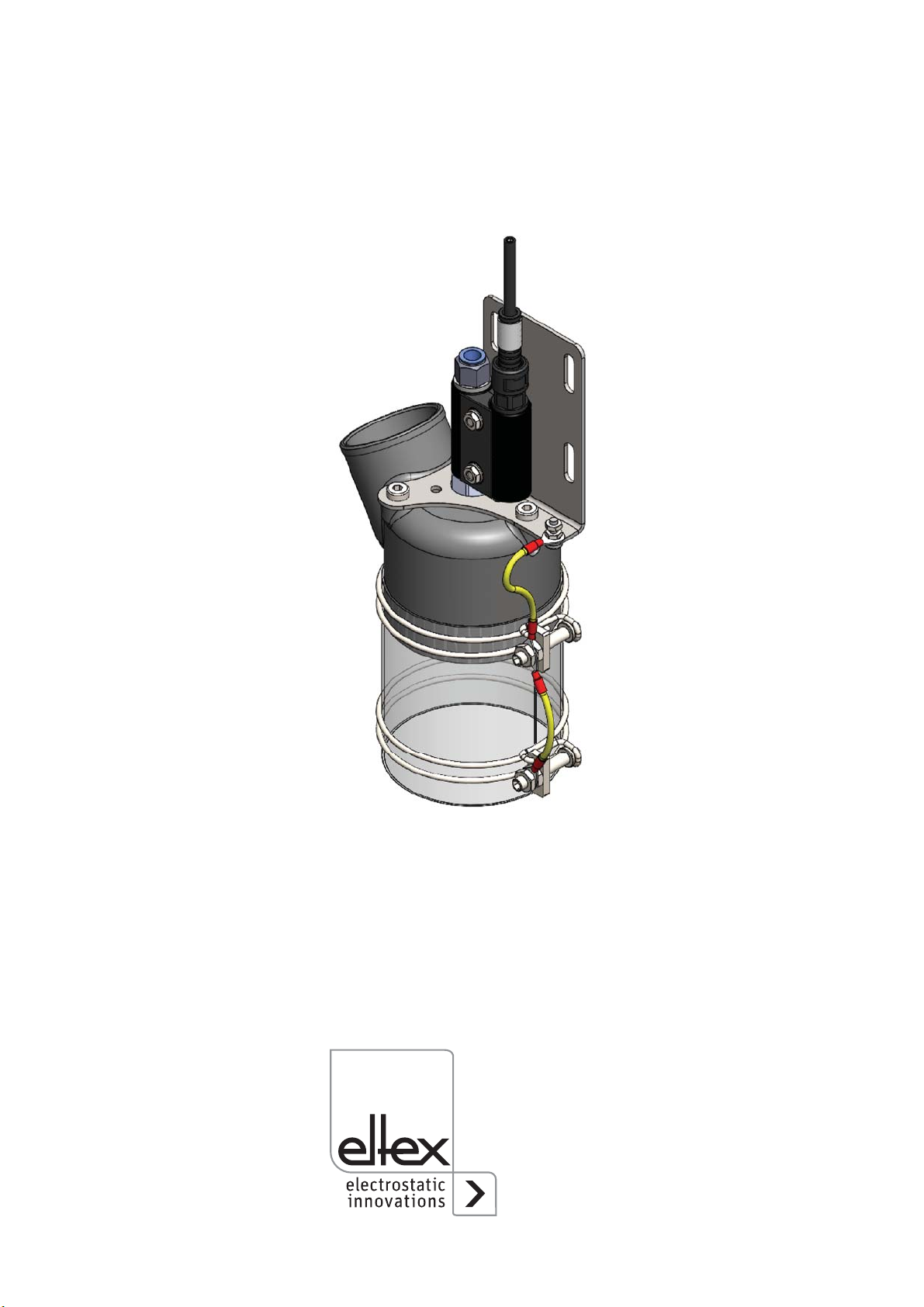
1. Outline of appliance
1 Compressed air connection
2 High voltage connection
3 Suction connection
4 Mounting plate
5 Speed sensor
6 Unit grounding bolt
7 Grounding of the metal attachments
8 Suction apron (for shortening)
Fig. 1:
Overview Static
Combi Cleaner
SCC-P
Z-118074y_2
8BA-en-2087-2207_Static Combi Cleaner SCC-P
2. Safety
The units have been designed, built and tested using state-of-the-art engi-
neering, and have left the factory in a technically and operationally safe
condition. If used improperly, the units may nevertheless be hazardous to
personnel and may cause injury or damage. Read the operating instruc-
tions carefully and observe the safety instructions.
For warranty conditions, please refer to the General Terms and Conditions
(GTC), see www.eltex.de.
2.1 Identification of risks and hazards
Possible risks and hazards resulting from the use of the units are referred
to in these operating instructions by the following symbols:
Warning!
This symbol appearing in the operating instructions refers to operations
which, if carried out improperly, may result in serious personal injuries.
Caution!
This symbol appearing in the operating instructions refers to operations
which, if carried out improperly, may result in damage to property.
2.2 Contact protection
The site of installation and/or use of the units is outside the control of
Eltex, contact protection against inadvertent contact of the bars and of live
components by personnel as specified by the employer’s liability insu-
rance association may have to be provided (e.g. DGUV V3 in Germany).
Contact protection devices made of conductive material must be
grounded.
2.3 Inspection of the protective resistors - contact protection
The function and the appearance of the protective resistors must be
inspected at regular intervals. The inspection intervals are specified in the
accident prevention regulations, as amended (e.g. in Germany DGUV
V3).
The function of the series resistors must be checked using a suitable
measuring device. The test voltage must be 1,000V. The measured resis-
tance between the high-voltage connection and the individual emission tip
must not fall below 80 MOhm and not exceed 120 MOhm.
Please additionally observe the operating instructions for the ion blower
nozzles R36, BA-en-2043.

BA-en-2087-2207_Static Combi Cleaner SCC_P 9
2.4 Technical advance
The manufacturer reserves the right to make changes to the technical
specifications without prior notice in order to adapt the units to state-of-
the-art engineering. Eltex will provide the latest information on any
changes or modifications in the operating instructions on request.
2.5 Proper use
The Static Combi Cleaner may be used only as an ionization cleaning
station for the non-contacting cleaning of surfaces and for cleaning and
drying work pieces and tools.
The integrated ion blower nozzles R36 may only be operated with the
Eltex power supply units with max. 6 kV AC. Only these allow optimum
adaptation to the required operating conditions.
Other uses are not permitted. The manufacturers will not assume any lia-
bility and warranty if the units are used improperly or used outside the
intended purpose.
Modifications or changes made to the devices are not permitted.
Use only original Eltex spare parts and equipment.

10 BA-en-2087-2207_Static Combi Cleaner SCC-P
2.6 Work and operational safety
Warning!
Carefully observe the following notes and the complete chapter 2 "Safety”,
page 8!
• Before carrying out repairs, cleaning or maintenance work and before
resetting after malfunctions, switch off the power supply and disconnect
the mains supply voltage (see chapter 5 "Maintenance”, page 17, chap-
ter 5 "Maintenance”, page 17).
• Before carrying out any work involving the units, the machine which has
the units fitted must not be in operation (see chapter 5 "Maintenance”,
page 17, chapter 5 "Maintenance”, page 17).
• Any work involving the units must be carried out by qualified electrici-
ans (see chapter 5 "Maintenance”, page 17, chapter 6 "Troubleshoo-
ting”, page 19).
• Connect/disconnect the high voltage cables only if the power supply
unit is switched off (see chapter 3.4 "Connecting the high voltage cable
to the ion blower nozzle”, page 14, chapter 3.5 "Connecting the high
voltage cable to the power supplies of series ES5x, ES6x and PI”,
page 14).
• For units with existing ground cables, these must be permanently con-
nected to ground potential. The ground cable should have a minimum
cross section of 1.5 mm2 (see chapter 3.6 "Connecting to ground”,
page 14).
• Check the units and the high voltage cables at regular intervals and
before startup for any damage. Any damaged components must be
repaired or replaced before continuing to operate the unit, or the units
must be disabled.
Warning!
The cable is permanently fixed to the R36 ion blower nozzle and must
on no account be changed; In the event of defects, please notify Eltex
Service or return the unit for repair.
• The high voltage cable must be routed to make sure that it does not
make contact with moving machine parts. Avoid mechanical deforma-
tions and bending radii smaller than 60 mm. The high voltabe cable must
not be installed on the floor, as it may break under load; the cable must
also not be subjected to tensile stress (see chapter 3.7 "Routing the high
voltage cable”, page 15).
• The air hose must be routed to make sure that it does not make contact
with moving machine parts. Avoid mechanical deformation and exces-
sively small bending radii (see manufacturer´s specifications); see
chapter 3.9 "Routing the air hose”, page 15.
• Cleaned apparatuses air must be used as compressed air (see chapter
3.10 "Compressed air properties”, page 15).

BA-en-2087-2207_Static Combi Cleaner SCC_P 11
• To ensure that the permissible operating temperature is not exceeded,
the blower nozzle must not be exposed to direct heat radiation (see
chapter 3.11 "Impact of heat radiation”, page 15).
• To avoid severe damage, keep other objects from hitting against the
nozzle (see chapter 4 "Operation”, page 16).
• Make sure that the units are clean at all times.
Dirt results in malfunctions and in premature wear of the units.
• When cleaning the units do not soak the units in solvent and do not
damage the emission tips; allow the solvent to evaporate completely
before restarting the unit (see chapter 5 "Maintenance”, page 17, chap-
ter 6 "Troubleshooting”, page 19).
• Do not touch the emission tips - risk of injury.
If the high voltage supply is connected, reflex responses to electrical
irritation can lead to secondary accidents. The charging bar as such is
safe to touch. If contact is made (single touch), the energy transferred
is so low that there is no risk of injury.
• Potential risk for wearers of cardiac pacemakers:
Moving the chest closer than 3.5 cm to the emission tips of the dis-
charging bar or making surface contact with several emission tips
(touching a single tip is not critical) can result in a temporary switchover
of the cardiac pacemaker into the fault mode. Permanent proximity or
contact can therefore cause severe problems. If it is likely that the chest
of such a person comes closer than 3.5 cm to the emission tips of the
discharging bar, or if several emission tips are touched at the same
time, the appropriate warning notices must be displayed.
• The operation of the units can generate ozone. The ozone concentra-
tion levels developing near the bars depend on many different factors
such as site of installation, bar current and voltage, air circulation, etc.,
and can therefore not be specified in general terms.
If the maximum allowable concentration of ozone must be observed at
the site of installation of the bar, the concentration must be
measured on site.
The AGW value (maximum admissible concentration) serves to assess
the ozone concentration at the workplace. The user must make sure
that the appropriate national AGW value is at no times exceeded, e.g.
in Germany the ozone concentration occurring during the operation of
the system must not exceed the recommended value based on interna-
tional limits of 0.06 ml/m³ (0.12 mg/m³).

12 BA-en-2087-2207_Static Combi Cleaner SCC-P
3. Installation and Assembly
3.1 Installation
The cleaning unit can be attached to the mounting plate. The distance to
the object is readjusted via the slotted holes.
The mounting plate can be rotated 120° in 3 positions.
Fig. 2:
Mounting plate
attachment
Z-118074y_4
Fig. 3:
Rotating the
mounting plate
Z-118074y_6
BA-en-2087-2207_Static Combi Cleaner SCC_P 13
3.2 Connecting the suction line
The unit is designed for a static conductive suction hose with a nominal dia-
meter of 50 mm in a light version. (e.g. Airduc PUR 351 EC D=50 mm).
Metal hose clamps must be grounded.
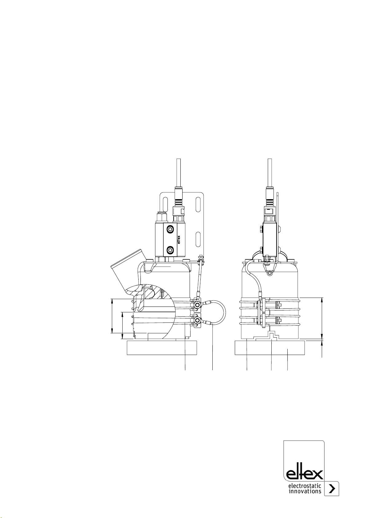
3.3 Adjusting the suction apron
The distance (A) of the rotation nozzle to the product in interaction with the
air pressure must be adjusted individually. To prevent the ablation from rea-
ching the surroundings, the apron should be guided as close as possible to
the object or the support system. If the gap (D) is less than or equal to
3 mm, complete suction is possible.
A Distance nozzle - workpiece 1 Mounting clip
B Extension dimension 2 Ground wire of the add-on cable
C Apron length 3 Cut contour of the suction apron
D Gap between apron 4 Workpiece (schematic)
and workpiece 5 Workpiece holder (schematic)
Fig. 4:
Apron adjustment
Z-118074y_5
"
#
%
$

14 BA-en-2087-2207_Static Combi Cleaner SCC-P
It is intended that the apron (3) be shortened to dimension (C) by the cus-
tomer and a contour be cut if necessary. The 1 mm thick conductive poly-
carbonate film should be worked on with a suitable cutting tool. From an
apron length (C) of less than 60 mm, the lower wire clamp is no longer
necessary..
3.4 Connecting the high voltage cable to the ion blower nozzle
The high voltage cable is fixed permanently to the ion blower nozzle.
3.5 Connecting the high voltage cable to the power supplies of
series ES5x, ES6x and PI
Warning!
Connect or disconnect the high voltage cables only with the power supply
switched off!
Connect the ion blower nozzles to the power supply using the prefabrica-
ted high voltage cable. Push the high voltage cables into the sockets up to
the stop. Then secure the cable in the socket with the clip provided (see
Fig. 5).
Warning!
In applications involving moving ion blower nozzles, the high voltage cable
must be attached such that there is no cable movement near the connec-
tion zone of the ion blower nozzles and the power supply unit. Use sui-
table clamps to attach the high voltage cables.
3.6 Connecting to ground
In units equipped with existing ground cables, the cables must be perma-
nently connected to ground potential. The ground cable should have a
minimum cross section of 1.5 mm2.
Fig. 5:
Connecting the
high voltage cable
Z00178y

BA-en-2087-2207_Static Combi Cleaner SCC_P 15
3.7 Routing the high voltage cable
The high voltage cable must be routed to make sure that it does not make
contact with moving machine parts. Avoid mechanical deformations and
bending radii smaller than 60 mm. The high voltabe cable must not be
installed on the floor, as it may break under load; the cable must also not be
subjected to tensile stress.
3.8 Connecting the compressed air
The R36 ion blower nozzle is supplied with a plug-in connection for pneu-
matic hoses with an outer diameter of 8 mm. The plug-in connection can
be replaced by other hose connections with a G 1/4" or R 1/4" screw
thread.
3.9 Routing the air hose
The air hose must be routed to make sure that it does not make contact
with moving machine parts. Avoid mechanical deformation and exces-
sively small bending radii (see manufacturer´s specifications).
3.10 Compressed air properties
The compressed air must be free from oil, water and dust. If the air supply
hoses are very long, a water separator must be fitted immediately
upstream from the ion blower nozzle, the ion blower pistol or the ion
blower nozzle bar. Maximum rated air pressure depends on the used
nozzle type (see chap. 7 Technical specifications).
3.11 Impact of heat radiation
To ensure that the permissible operating temperature is not exceeded, the
blower nozzle must not be exposed to direct heat radiation.
Please also observe the operating instructions for the ion blower nozzles
R36, BA-en-2043 for all connections.

16 BA-en-2087-2207_Static Combi Cleaner SCC-P
4. Operation
4.1 Startup
Once all the connections have been made correctly, the system is opera-
tional and the supply voltage can be switched on at the power supply. The
ion blower nozzle and the ionization cleaning station are operational now.
4.2 Operating voltage
The ion blower nozzles are supplied via the Eltex high voltage supply unit
and are operated with an optimum operating voltage of 3.5 - 6 kV.
4.3 Function control
Use the Eltex Volt Stick or a glow-lamp voltage tester to check the proper
function of the emission tips. Quote Article No. 109136 when ordering the
Volt Stick from Eltex.
Caution!
To avoid severe damage, keep other objects from hitting against the
nozzle!

BA-en-2087-2207_Static Combi Cleaner SCC_P 17
5. Maintenance
Warning!
Electric shock hazard!
• Switch off the power supply unit and disconnect the supply voltage
before carrying out any maintenance or repair work.
• The bars passively absorb energy from the moving substrate web. The
high voltage cable must be plugged in or grounded to the generator. If
the high voltage cable is disconnected, the plug is live (high voltage) and
applies with full power on the plug; this may cause a spark discharge and
may lead to a risk of injury. Disconnected high voltage plugs are not per-
mitted or have to be grounded.
• The machine which has the units fitted must not be in operation.
• Repairs and maintenance work must be carried out by qualified electrici-
ans only.
• Disconnect the compressed air supply before carrying out any mainte-
nance or repair work.
5.1 Cleaning
To ensure the trouble-free function of the ion blower nozzles, the surface
from which the emission tip and the blown air exit must be clean and dry at
all times. Dirty blower nozzles must be cleaned with a suitable solvent (ben-
zine) and a brush with soft plastic bristles (Eltex article RBR22). To prevent
the air exit holes from clogging up with dirt during cleaning, the compressed
air (0.3...0.5 x 105 Pa) must be switched on during cleaning.
Warning!
Risk of deflagration!
Allow the solvent to evaporate completely before restarting the unit.
Caution!
Do not damage the emission tips when cleaning.

18 BA-en-2087-2207_Static Combi Cleaner SCC-P
5.2 Inspection of the protective resistors - contact protection
The function and the appearance of the protective resistors must be
inspected at regular intervals. The inspection intervals are specified in
the accident prevention regulations, as amended (e.g. in Germany DGUV
V3).
The function of the series resistors must be checked using a suitable
measuring device. The test voltage must be 1,000V. The measured resis-
tance between the high-voltage connection and the individual emission tip
must not fall below 80 MOhm and not exceed 120 MOhm.
Please additionally observe the operating instructions for the ion blower
nozzles R36, BA-en-2043.

BA-en-2087-2207_Static Combi Cleaner SCC_P 19
6. Troubleshooting
Warning!
Electric shock hazard!
• Switch off the power supply unit and disconnect the supply voltage
before carrying out any maintenance or repair work.
• The machine which has the units fitted must not be in operation.
• Repairs and maintenance work must be carried out by qualified electri-
cians only.
• Disconnect the compressed air supply before carrying out any mainte-
nance or repair work.
For other malfunctions, see also the operating instructions for the power
supply.
Fault Cause Measure
Efficiency of
the applica-
tion declines.
Dirt on ion
blower nozzle /
pistol /
nozzle bar.
Clean ion blower nozzle / pistol with
compressed air and a plastic brush.
Grease, oil, inks, etc. on the blower
nozzle / pistol must be cleaned off using
a suitable solvent (benzine).
Caution!
Allow the solvent to evaporate com-
pletely before restarting the unit. Do not
soak the blower nozzle / pistol in solvent.
Short circuit in
the high voltage
cable.
If required, exchange the high voltage
cable at the R36 ion blower nozzle.
In the event of defective high voltage
cables at the PR36 ion blower pistol and
the LR36 ion blower nozzle bar, please
notify Eltex Service or return the com-
plete unit for repair. Do not replace or
exchange the cable.
Defective ion
blower nozzle /
pistol /
nozzle bar.
Check the blower nozzle / pistol / nozzle
bar for any damage caused by leakage
currents. If more than one blower nozzle
/ pistol /
nozzle bar is connected to the power
supply, disconnect all devices and
replace one after the other device to
localize the defective blower nozzle /
pistol / nozzle bar. Replace the defective
device.
20 BA-en-2087-2207_Static Combi Cleaner SCC-P
7. Technical specifications
Operating voltag
High voltage supply
Operating ambient
temperature
Ambient humidity
Contact protection
Air connection
Air pressure
Dimensions
Weight
3.5 - 6 kV, 50 - 250 Hz
via Eltex power supplies,
operating voltage max. 6 kV AC
0...+60 °C (+32...+140 °F)
max. 70 % r. F., no dewing permitted
contect protected according to EN 61140
Plug-in connection 8 mm
max. 2.5 to 6 x 10⁵ Pa,
see table air consuption
approx. 120 x 90 x 220 mm (L x W x H)
approx. 0.7 kg, without high voltage cable
Nozzle insert Ø [mm] Guide values
air consumption [Nm³/h]
at [6 x 10⁵ Pa]
0.8
1.1
1.4
1.6
5.8
8.5
10.8
12.2
Table of contents


