Elu ELU27158 User manual

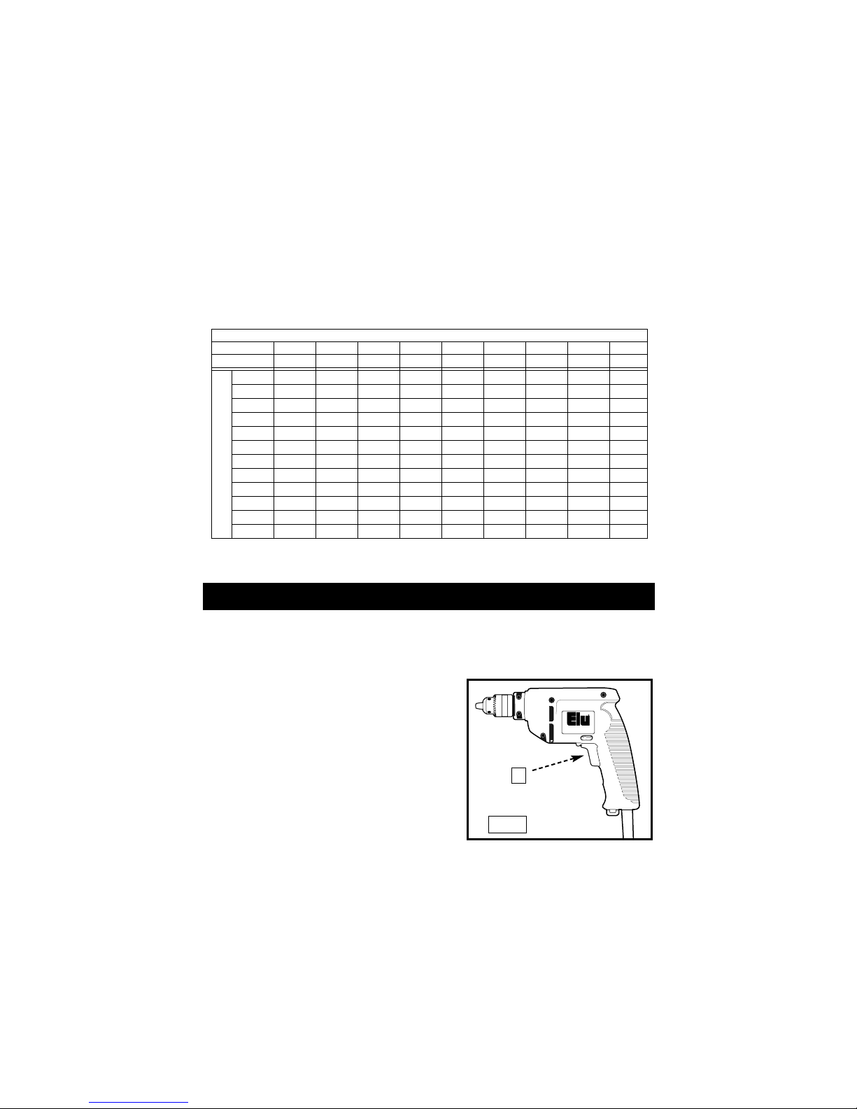
The Model and Serial No. plate is located on the main
housing of the tool. Record these numbers in the
spaces below and retain for future reference.
Model No. ______________________________________
Type ___________________________________________
Serial No. _______________________________________
IMPORTANT
Please make certain that the person who is to use
this equipment carefully reads and understands these
instructions before starting operations.
1/2" Drill
ELU27158


1
Read and understand all warnings and operating instructions
before using any tool or equipment. When using tools or equipment, basic
safety precautions should always be followed to reduce the risk of personal
injury. Improper operation, maintenance or modification of tools or equipment
could result in serious injury and property damage. There are certain
applications for which tools and equipment are designed. Elu strongly
recommends that this product NOT be modified and/or used for any application
other than for which it was designed.
Information regarding the safe and proper operation of this tool is available from
the following sources:
Power Tool Institute
1300 Sumner Avenue, Cleveland, OH 44115-2851
National Safety Council
1121 Spring Lake Drive, Itasca, IL 60143-3201
American National Standards Institute, 25 West 43rd Street, 4 floor, New York,
NY 10036 www.ansi.org ANSI 01.1Safety Requirements for Woodworking
Machines, and the U.S. Department of Labor regulations www.osha.gov
SAVE THESE INSTRUCTIONS!
IMPORTANT SAFETY INSTRUCTIONS . . . . . . . . . . . . . . . . . . . . . . . . . .1
SAFETY GUIDELINES . . . . . . . . . . . . . . . . . . . . . . . . . . . . . . . . . . . . . . . .2
GENERAL SAFETY RULES . . . . . . . . . . . . . . . . . . . . . . . . . . . . . . . . . . .3
ADDITIONAL SPECIFIC SAFETY RULES . . . . . . . . . . . . . . . . . . . . . . . .5
FUNCTIONAL DESCRIPTION . . . . . . . . . . . . . . . . . . . . . . . . . . . . . . . . .7
ASSEMBLY . . . . . . . . . . . . . . . . . . . . . . . . . . . . . . . . . . . . . . . . . . . . . . . .9
OPERATION . . . . . . . . . . . . . . . . . . . . . . . . . . . . . . . . . . . . . . . . . . . . . . .9
MAINTENANCE . . . . . . . . . . . . . . . . . . . . . . . . . . . . . . . . . . . . . . . . . . . .10
SERVICE . . . . . . . . . . . . . . . . . . . . . . . . . . . . . . . . . . . . . . . . . . . . . . . . .11
ACCESSORIES . . . . . . . . . . . . . . . . . . . . . . . . . . . . . . . . . . . . . . . . . . . .11
WARRANTY . . . . . . . . . . . . . . . . . . . . . . . . . . . . . . . . . . . . . . . . . . . . . . .11
TABLE OF CONTENTS
IMPORTANT SAFETY INSTRUCTIONS
2
Some dust created by power sanding, sawing, grinding, drilling,
and other construction activities contains chemicals known (to the
State of California) to cause cancer, birth defects or other reproductive harm. Some
examples of these chemicals are:
• lead from lead-based paints
• crystalline silica from bricks and cement and other masonry products
• arsenic and chromium from chemically-treated lumber
Your risk from these exposures varies, depending on how often you do this type
of work. To reduce your exposure to these chemicals: work in a well ventilated
area, and work with approved safety equipment, always wear NIOSH/OSHA
approved, properly fitting face mask or respirator when using such tools.
indicates an imminently hazardous situation which, if not
avoided, will result in death or serious injury.
indicates a potentially hazardous situation which, if not
avoided,could result in death or serious injury.
indicates a potentially hazardous situation which, if not
avoided,may result in minor or moderate injury.
used without the safety alert symbol indicates potentially
hazardous situation which, if not avoided, may result in
property damage.
CALIFORNIA PROPOSITION 65
It is important for you to read and understand this manual. The
information it contains relates to protecting YOUR SAFETY and
PREVENTING PROBLEMS. The symbols below are used to help
you recognize this information.
SAFETY GUIDELINES - DEFINITIONS

3
SAVE THESE INSTRUCTIONS
WORK AREA
• Keep your work area clean and well lit. Cluttered benches and dark areas
invite accidents.
• Do not operate power tools in explosive atmospheres, such as in the
presence of flammable liquids, gases, or dust. Power tools create sparks
which may ignite the dust or fumes.
• Keep bystanders, children, and visitors away while operating a power
tool. Distractions can cause you to lose control.
ELECTRICAL SAFETY
• Grounded tools must be plugged into an outlet properly installed and
grounded in accordance with all codes and ordinances. Never remove the
grounding prong or modify the plug in any way. Do not use any adaptor plugs.
Check with a qualified electrician if you are in doubt as to whether the outlet is
properly grounded. If the tools should electrically malfunction or break down,
grounding provides a low resistance path to carry electricity away from the
user. Some units are grounded. Applicable only to Class I (grounded) tools.
• Double insulated tools are equipped with a polarized plug (one blade is
wider than the other.) This plug will fit in a polarized outlet only one way. If
the plug does not fit fully in the outlet, reverse the plug. If it still does not fit,
contact a qualified electrician to install a polarized outlet. Do not change the
plug in any way. Double insulation eliminates the need for the three wire
grounded power cord and grounded power supply system. Applicable only to
Class II (double insulated) tools. Some units are rated at 230 volts and they
are fitted with the 220 volt style plug which is not polarized.
• Avoid body contact with grounded surfaces such as pipes, radiators,
ranges and refrigerators. There is an increased risk of electric shock if your
body is grounded.
• Don’t expose power tools to rain or wet conditions. Water entering a
power tool will increase the risk of electric shock.
• Do not abuse the cord. Never use the cord to carry the tools or pull the plug
from an outlet. Keep cord away from heat, oil, sharp edges or moving parts.
Replace damaged cords immediately. Damaged cords increase the risk of
electric shock.
• When operating a power tool outside, use an outdoor extension cord
marked “W-A” or “W.” These cords are rated for outdoor use and reduce the
risk of electric shock. When using an extension cord, be sure to use one heavy
enough to carry the current your product will draw. An undersized cord will
cause a drop in line voltage resulting in loss of power and overheating. The
following table shows the correct size to use depending on cord length and
nameplate ampere rating. If in doubt, use the next heavier gage. The smaller
the gage number, the heavier the cord.
Read and understand all instructions. Failure
to follow all instructions listed below may result in electric shock,
fire and/or serious personal injury.
GENERAL SAFETY RULES

4
GENERAL SAFETY RULES continued
PERSONAL SAFETY
• Stay alert, watch what you are doing and use common sense when
operating a power tool. Do not use tool while tired or under the influence of
drugs, alcohol, or medication. A moment of inattention while operating power
tools may result in serious personal injury,
• Dress properly. Do not wear loose clothing or jewelry. Contain long hair.
Keep your hair, clothing, and gloves away from moving parts. Loose clothing,
jewelry, or long hair can be caught in moving parts. Air vents often cover
moving parts and should also be avoided.
• Avoid accidental starting. Be sure switch is off before plugging in. Carrying
tools with your finger on the switch or plugging in tools that have the switch on
invites accidents.
• Remove adjusting keys or switches before turning the tool on. A wrench
or key that is left attached to a rotating part of the tool may result in personal
injury.
• Do not overreach. Keep proper footing and balance at all times. Proper
footing and balance enables better control of the tool in unexpected situations.
• Use safety equipment. Always wear eye protection. Dust mask, non-skid
safety shoes, hard hat, or hearing protection must be used for appropriate
conditions.
TOOL USE AND CARE
• Use clamps or other practical way to secure and support the workpiece
to a stable platform. Holding the work by hand or against your body is
unstable and may lead to loss of control.
• Do not force tool. Use the correct tool for your application. The correct tool
will do the job better and safer at the rate for which it is designed.
• Do not use tool if switch does not turn it on or off. Any tool that cannot be
controlled with the switch is dangerous and must be repaired.
• Disconnect the plug from the power source before making any
adjustments, changing accessories, or storing the tool. Such preventative
safety measures reduce the risk of starting the tool accidentally.
• Store idle tools out of reach of children and other untrained persons.
Tools are dangerous in the hands of untrained users.
• Maintain tools with care. Keep cutting tools sharp and clean. Properly
maintained tools, with sharp cutting edges are less likely to bind and are
easier to control.
• Check for misalignment or binding of moving parts, breakage of parts,
and any other condition that may affect the tools operation. If damaged,
have the tool serviced before using. Many accidents are caused by poorly
maintained tools.
• Use only accessories that are recommended by the manufacturer for
your model. Accessories that may be suitable for one tool, may become
hazardous when used on another tool.

5
1. Hold tool by insulated gripping surfaces when performing an operation
where the cutting tools may contact hidden wiring or its own cord. Contact
with a “live” wire will make exposed metal parts of the tool “live” and shock
the operator.
2. Keep handles dry, clean, free from oil and grease. It is recommended to
use rubber gloves. This will enable better control
3. DO NOT TOUCH ANY METAL PARTS OF THE TOOL when drilling or
driving into walls, floors or wherever live electrical wires may be
encountered. Hold the tool only by insulated grasping surfaces to prevent
electric shock if you drill or drive into a live wire.
4. Wear eye and hearing protection. Always use safety glasses. Everyday
eyeglasses are NOT safety glasses. USE CERTIFIED SAFETY
EQUIPMENT. Eye protection equipment should comply with ANSI Z87.1
standards. Hearing equipment should comply with ANSI S3.19 standards.
5. Use of this tool can generate and disburse dust or
other airborne particles, including wood dust, crystalline silica dust
and asbestos dust. Direct particles away from face and body. Always
operate tool in well ventilated area and provide for proper dust removal.
Use dust collection system wherever possible. Exposure to the dust may
cause serious and permanent respiratory or other injury, including silicosis
(a serious lung disease), cancer, and death. Avoid breathing the dust, and
avoid prolonged contact with dust. Allowing dust to get into your mouth
or eyes, or lay on your skin may promote absorption of harmful material.
Always use properly fitting NIOSH/OSHA approved respiratory protection
appropriate for the dust exposure, and wash exposed areas with soap
and water.
ADDITIONAL SPECIFIC SAFETY RULES
GENERAL SAFETY RULES continued
SERVICE
• Tool service must be performed only by qualified repair personnel.
Service or maintenance performed by unqualified personnel could result in a
risk of injury.
• When servicing a tool, use only identical replacement parts. Follow
instructions in the Maintenance section of this manual. Use of unauthorized
parts or failure to follow Maintenance Instructions may create a risk of electric
shock or injury.

6
SAVE THESE INSTRUCTIONS!
MOTOR
Many tools will operate on either D.C., or single phase 25 to 60 cycle A.C.
current and voltage within plus or minus 5 percent of that shown on the
specification plate on the tool. Several models, however, are designed for A.C.
current only. Refer to the specification plate on your tool for proper voltage and
current rating.
Do not operate your tool on a current on which the voltage is not
within correct limits. Do not operate tools rated A.C. only on D.C. current. To do
so may seriously damage the tool.
SYMBOL DEFINITION
V ..........................................volts
A ..........................................amperes
Hz ........................................hertz
W ........................................watts
min ......................................minutes
........................................alternating current
....................................direct current
no ........................................no load speed
........................................Class II Construction
........................................earthing terminal
........................................safety alert symbol
.../min ..................................revolutions per minute
7
EXTENSION CORD SELECTION
If an extension cord is used, make sure the conductor size is large enough to
prevent excessive voltage drop which will cause loss of power and possible
motor damage. A table of recommended extension cord sizes will be found in
this section. This table is based on limiting line voltage drop to 5 volts (10 volts
for 230 volts) at 150% of rated amperes.
If an extension cord is to be used outdoors, it must be marked with the suffix
W-A or W following the cord type designation. For example – SJTW-A to indicate
it is acceptable for outdoor use.
RECOMMENDED EXTENSION CORD SIZES FOR USE WITH PORTABLE ELECTRIC TOOLS
Length of Cord in Feet
115V 25 Ft. 50 Ft. 100 Ft. 150 Ft. 200 Ft. 250 Ft. 300 Ft. 400 Ft. 500 Ft.
230V 50 Ft. 100 Ft. 200 Ft. 300 Ft. 400 Ft. 500 Ft. 600 Ft. 800 Ft. 1000 Ft.
0-2 18 18 18 16 16 14 14 12 12
2-3 18 18 16 14 14 12 12 10 10
3-4 18 18 16 14 12 12 10 10 8
4-5 18 18 14 12 12 10 10 8 8
5-6 18 16 14 12 10 10 8 8 6
6-8 18 16 12 10 10 8 6 6 6
8-10 18 14 12 10 8 8 6 6 4
10-12 16 14 10 8 8 6 6 4 4
12-14 16 12 10 8 6 6 6 4 2
14-16 16 12 10 8 6 6 4 4 2
16-18 14 12 8 8 6 4 4 2 2
18-20 14 12 8 6 6 4 4 2 2
Nameplate Ampere Rating
SAVE THESE INSTRUCTIONS!
MOTOR BRUSHES
ELU uses an advanced brush system which automatically stops the drill when
the brushes wear out. This prevents serious damage to the motor.
FUNCTIONAL DESCRIPTION
Fig. 1
A
SWITCH
To start drill, depress trigger switch; to stop
the drill, release trigger. To lock trigger in the
on position for continuous operation, depress
trigger and push up locking button “A” shown
in figure 1, then gently release the trigger. To
release the locking mechanism, depress the
trigger fully, then release it. Before using the
tool each time, be sure that the locking
button release mechanism is working freely.
Do not lock the switch on when drilling by
hand so that you can instantly release the
trigger switch if the bit binds in the hole.
The locking button is for use only when the drill is mounted in a drill press stand
or otherwise held stationary.
Be sure to release the locking button before disconnecting the plug from the
power supply. Failure to do so will cause the tool to start immediately the next
time it is plugged in. Damage or injury could result.

SWITCH
ASSEMBLY
LOCK-OUT KEY
8
THE VARIABLE SPEED TRIGGER SWITCH
This switch permits speed control: the farther the trigger is depressed, the higher
the speed of the drill.
NOTE: Use lower speeds for starting holes without a center punch, drilling in
metal or plastics, driving screws or drilling ceramics. Higher speeds are better for
drilling wood and composition boards, and for using abrasive and polishing
accessories.
THE REVERSING LEVER
The reversing lever changes the direction of
rotation of the drill and is used when backing
out screws and jammed drill bits. To operate
the tool in reverse, release the trigger switch
and push the lever to the left (when viewed
from the chuck end) as shown in Figure 2. To
operate the drill in forward for drilling holes or
driving screws (as well as when using other
accessories) release the trigger switch and
push the lever to the right (when viewed from
the chuck end).
Return the reversing lever to the forward
position after all operations in reverse are
completed.
SWITCH LOCK-ON
Your drill is equipped with a switch lock-on feature. If you wish to disable this
feature, take your tool to any authorized service center. The service center can
provide a lock-out key to prevent the unit from being locked in the on position
(Figure 3).
REVERSING
LEVER
(Shown in
Forward Position)
Fig. 2
Fig. 3

9
DRILLING
1. Always unplug the drill when attaching or changing bits or accessories.
2. Use sharp drill bits only. For WOOD, use twist drill bits, spade bits, power auger
bits, or hole saws. For METAL, use high speed steel twist drill bits or hole saws.
For MASONRY, such as brick, cement, cinder block, etc., use carbide-tipped
bits.
3. Be sure the material to be drilled is anchored or clamped firmly. If drilling thin
material, use a wood “back-up” block to prevent damage to the material.
4.Always apply pressure in a straight line with the bit. Use enough pressure to keep
the drill biting, but do not push hard enough to stall the motor or deflect the bit.
5. Hold the tool firmly to control the twisting action of the drill.
6. IF THE DRILL STALLS, it is usually because it is being overloaded or
improperly used. RELEASE THE TRIGGER IMMEDIATELY, remove the drill
bit from work, and determine cause of stalling. DO NOT CLICK TRIGGER OFF
AND ON IN AN ATTEMPT TO START A STALLED DRILL — THIS CAN
DAMAGE THE DRILL.
7. To minimize stalling or breaking through the material, reduce pressure on drill
and ease the bit through the last fractional part of the hole.
8. Keep the motor running when pulling the bit out of a drilled hole. This will help
prevent jamming.
9. With Variable Speed Drills there is no need to center punch the point to be
drilled. Use a slow speed to start the hole and accelerate by squeezing the
trigger harder when the hole is deep enough to drill without the bit skipping out.
KEYED CHUCKS
Open chuck jaws by turning collar with fingers and insert shank of bit about 3/4"
into chuck. Tighten chuck collar by hand. Place chuck key in each of the three
holes, and tighten in CLOCKWISE direction. It’s important to tighten chuck with
all three holes to prevent slippage. To release bit, turn chuck key
COUNTERCLOCKWISE in just one hole, then loosen the chuck by hand. Any
authorized DEWALT service center can install a keyless chuck in place of a
keyed chuck.
OPERATION
ASSEMBLY
NOTE: This tool is shipped completely assembled. No assembly time or tools
are required.
SIDE HANDLE
A side handle may be supplied with your drill. The side handle clamps to the
front of the gear case and can be rotated 360 degrees to permit right or left hand
use.
If a side handle is included with your drill, always use it and hold
the drill with both hands.

10
KEEP TOOL CLEAN
Periodically blow out all air passages with dry compressed air. All plastic parts
should be cleaned with a soft damp cloth. NEVER use solvents to clean plastic
parts. They could possibly dissolve or otherwise damage the material.
FAILURE TO START
Should your tool fail to start, check to make sure the prongs on the cord plug are
making good contact in the outlet. Also, check for blown fuses or open circuit
breakers in the line.
BRUSH INSPECTION (If applicable)
For your continued safety and electrical protection, brush inspection and
replacement on this tool should ONLY be performed by an AUTHORIZED ELU
SERVICE STATION.
At approximately 100 hours of use, take or send your tool to your nearest
authorized service station to be thoroughly cleaned and inspected. Have worn
parts replaced and lubricated with fresh lubricant. Have new brushes installed
and test the tool for performance.
Any loss of power before the above maintenance check may indicate the need
for immediate servicing of your tool. DO NOT CONTINUE TO OPERATE TOOL
UNDER THIS CONDITION. If proper operating voltage is present, return your
tool to the service station for immediate service.
MAINTENANCE
KEYLESS CHUCKS
Open chuck jaws by turning plastic collar with fingers and insert shank of bit
about 3/4" into chuck. Tighten plastic collar CLOCKWISE while depressing
spindle lock button on the right side of the tool housing (Fig. 4). To release bit,
turn plastic collar COUNTERCLOCKWISE while depressing the spindle lock
button (Fig. 4). NOTE: DO NOT DEPRESS LOCK BUTTON WHILE
OPERATING DRILL or while the chuck is moving.
DRILLING IN METAL
Use a cutting lubricant when drilling metals. The exceptions are cast iron and
brass which should be drilled dry. The cutting lubricants that work best are
sulfurized cutting oil or lard oil; bacon-grease will also serve the purpose.
DRILLING IN WOOD
Holes in wood can be made with the same twist drills used for metal. These bits
may overheat unless pulled out frequently to clear chips from the flutes. For
larger holes, use power drill wood bits. Work that is apt to splinter should be
backed up with a block of wood.
DRILLING IN MASONRY
Use carbide tipped masonry bits at low speeds. Keep an even force on the drill
but not so much that you crack the brittle materials. A smooth, even flow of dust
indicates the proper drilling rate.

11
REPLACEMENT PARTS
When servicing use only identical replacement parts.
SERVICE AND REPAIRS
All quality tools will eventually require servicing, or replacement of parts due to
wear from normal use. All repairs made by the service centers are fully
guaranteed against defective material and workmanship. We cannot guarantee
repairs made or attempted by others.
Should you have any questions about your tool, call 1-800-54-HOW-TO (544-
6986) or feel free to write us at any time. In any communications, please give all
information shown on the nameplate of your tool (model number, type, serial
number, etc.).
SERVICE
Recommended accessories for use with your tool are available at extra cost from
your distributor or local service center.
ACCESSORY MUST BE RATED FOR USE AT SPEED EQUAL TO OR
HIGHER THAN NAMEPLATE R.P.M. OF TOOL WITH WHICH IT IS BEING
USED.
The use of any non-recommended accessory may be
hazardous.
Elu industrial tools are warranted for one year from date of purchase. We will
repair, without charge, any defects due to faulty materials or workmanship. For
warranty repair information, call your local Black & Decker service center. This
warranty does not apply to accessories or damage caused where repairs have
been made or attempted by others. This warranty gives you specific legal rights
and you may have other rights which vary in certain states or provinces.
In addition to the warranty, ELU tools are covered by our:
30 DAY NO RISK SATISFACTION GUARANTEE
If you are not completely satisfied with the performance of your ELU power tool,
simply return it to the participating seller within 30 days for a full refund. Please
return the complete unit, transportation prepaid. Proof of purchase may be
required.
ACCESSORIES
WARRANTY


BLACK & DECKER (U.S.) INC., 701 East Joppa Road, Baltimore, MD 21286
(JUN05) Form No. 633074-00 ELU27158 Copyright ©
2005 Elu Industrial Power Tools
Table of contents
Other Elu Drill manuals


