ELVA-1 MobiBridge-10G User manual

ELVA-1 Microwave HB
ELVA-1 OU, 2 korrus, Pärnu mnt.160j,
Tallinn, 11317, Estonia
Web: elva-1.com
This document is confidential, privileged and only for the information of the intended recipient.
***
All information from this document is protected by the related copyright, patent, or intellectual property right. ELVA-1 has
the exclusive right to change this information in order to improve performance and/or usability of the described product.
Copyright © 2023, ELVA-1 OU
USER MANUAL
for Web Interface of V-band 10 Gbps Radio
MobiBridge-10G
WEB INTERFACE

MobiBridge-10G Web Interface Guide
1
Contents
Disclaimer to using MobiBridge 10G web interface settings 2
Radio Link Terminology 2
WEB INTERFACE CONNECTIVITY OVERVIEW 3
Introduction 3
Connectivity diagram 3
RUNNING WEB INTERFACE FOR THE FIRST TIME LOGIN 5
General information 5
Working with 1 Gigabit Ethernet ports 5
Understanding Web Interface Color Indicators 5
First Login to Radios 6
Operational Status Tab 7
Statistics Tab 8
IP Settings Tab 9
Settings Tab 10
RFMs QuickList Tab 11
Reboot and Exit 12

MobiBridge-10G Web Interface Guide
2
DISCLAIMER TO USING MOBIBRIDGE 10G WEB INTERFACE SETTINGS
The following provisions, important to the limitation of ELVA-1's area of responsibility, apply to this
document.
•This document is described the web interface of volume MobiBridge-10G products.
•ELVA-1 may, from time to time, make changes to the web interface to improve the user
experience.
•ELVA-1 is not responsible for any interruption of MobiBridge-10G wireless connection
caused by malfunction of the customer's local network or the Internet, which may
interfere with the operation of the MobiBridge-10G.
•ELVA-1 is not responsible for any customer losses that may occur if the MobiBridge-10G
wireless connection fails. This covers equipment failure and incorrect setting of operation
modes using the web interface.
•Faulty MobiBridge-10G equipment will be repaired or replaced under warranty or at an
additional charge by contacting ELVA-1 technical support.
RADIO LINK TERMINOLOGY
•Link –set of two radios, with wireless connection between them
•Radio –fully integrated device for wireless connection with other radio, including 10 Gigabit
Ethernet port, modem and RF (radio frequency) components with built-in antenna
•Modem –part of radio, including 10 Gigabit Ethernet components, Transmitter (Tx) and
Receiver (Rx) components. Modem transmits and receives data between fiber-optics cable
and wireless signal from antenna with RF components.
•Transceiver –set of Transmitter (Tx) and Receiver (Rx)
•RF components –hi-tech set of millimeter wave components, that exchange data flow
between modem and antenna.
MobiBridge-10G Web Interface Guide
3
WEB INTERFACE CONNECTIVITY OVERVIEW
INTRODUCTION
The MobiBridge-10G radios can be accessed by IP addresses via LAN, WAN or directly by cable
from a laptop through the RJ-45 port (the radios have a graphical interface). To do this, the
MobiBridge-10G must be installed at the site, powered and cables from both radios connected to
the LAN on each side of the radio link.
The MobiBridge-10G radio can be accessed via the web interface. Any available web browser may
be used, while Google Chrome is recommended. Desktop PCs, notebooks, tablets and smartphones
are supported to get web access to MobiBridge-10G radios for either Windows, macOS/iOS and
Android operating systems. Please note that the MobiBridge-10G web interface may not be adapted
for the mobile device screen.
CONNECTIVITY DIAGRAM
By factory default, each MobiBridge-10G radio has IP address for web access. These IP addresses
are different –the device with even serial number has internal IP address 192.168.127.254,
while odd serial number - 192.168.127.253. For actual serial number of your device, check the
label on the radio enclosure.
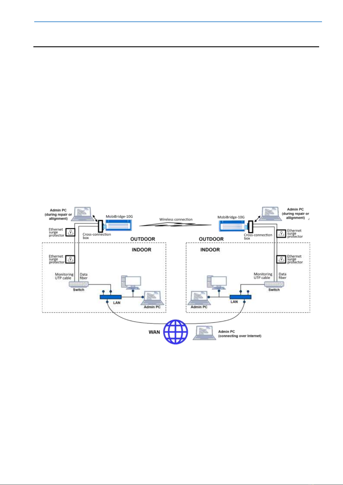
Fig.1. LAN / WAN web access connectivity to radios
The diagram shows all possible cases where a system administrator (aka Admin) can connect to
each radio by its IP address in three ways:
1. Connect from Admin PC (notebook or mobile device) to the radio while are in the same LAN.
2. Connect from Admin PC (desktop, notebook or mobile device) to the radio over WAN (over
the Internet). In this case both radios have to have static IP addresses accessed globally.
Otherwise, Virtual Desktop technology could also be used for remote connection from
Internet to a computer inside LAN, then running web browser on this computer and do all
works as within LAN.
MobiBridge-10G Web Interface Guide
4
3. Directly connect from Admin PC (using PC/notebook with Ethernet port) to the radio by UTP
cable with RJ-45 connectors. This way usually used only in some situations of initial
installation of the link or at link repair works.
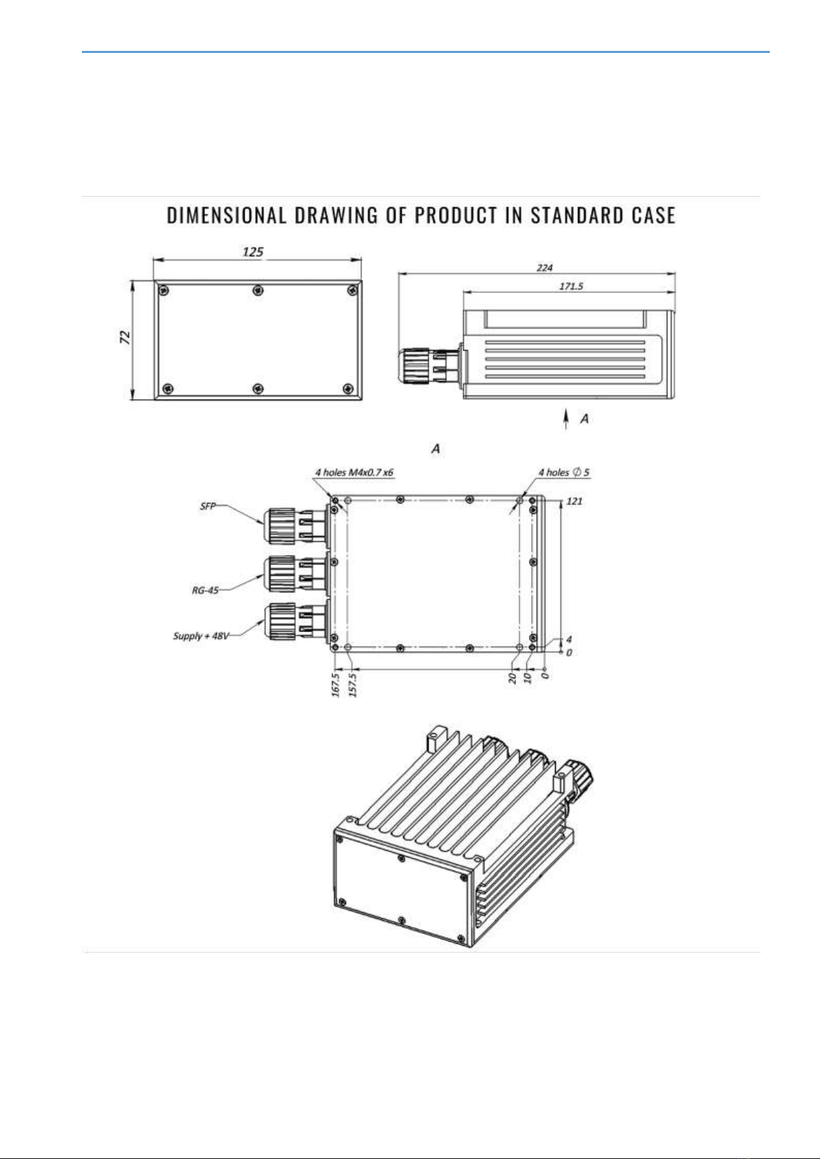
See Fig.2 below for radio’s sockets identification.
Fig.2. MobiBridge-10G drawing

MobiBridge-10G Web Interface Guide
5
RUNNING WEB INTERFACE FOR THE FIRST TIME LOGIN
GENERAL INFORMATION
The information in this User Guide is directed to person(s) who will perform or coordinate the tasks
associated with the process of installing and administering of MobiBridge-10G connection within
LAN/WAN network. In general, this is system administrator or network administrator, named
Admin for short.
This guide assumes that Admin has experience with and understanding of the concepts underlying
wireless communications and LAN/WAN systems, as well as familiarity with configuring and
operating network environment.
During the initial (first time) login and use of the Web Interface, Admin runs the following tasks^
•Switch both radios to fix throughput mode and activate link wireless data transmitting
channel,
•Run wireless channel auto-setup for both radios to allow max wireless data rate,
•Switch both radios to Adaptive throughput mode (optional, valid for fixed wireless line),
•Change IP addresses for both radios from default to actual ones,
•Change Admin password for both radios from default to actual ones.
Note. Please mind that actual view of web interface might be slightly differ from described here
because of its latest updateы.
WORKING WITH 1GIGABIT ETHERNET PORTS
If the radios operate with network equipment (LAN switch, etc.) that does not have 10 GE ports
(but only 1Gigabit Ethernet ports), each radio can be switched to 1 GE mode by pressing the 1G
button using the WEB interface.
Click 1G button on the screen (it will turn blue to indicate ON), then Save button. Repeat this
procedure for the second radio.
By factory default, both radios are set to 10G mode.
UNDERSTANDING WEB INTERFACE COLOR INDICATORS
Color light indicators are used in Web Interface to quickly inform Admin if the value of parameters
is within normal limits or not.
•Green light means normal work / good quality of signal or this monitored parameter is ON,
•Red light requires Admin interruption because of the parameter malfunction, or for
information that this parameter is OFF.
•Blue color of Set1G and Set10G buttons indicates which mode is currently ON.
MobiBridge-10G Web Interface Guide
6
FIRST LOGIN TO RADIOS
To connect to the MobiBridge-10G radio using its IP address, enter the default IP address in the
address bar of your browser. You can use any available browser, but Google Chrome is
recommended.
The factory default MobiBridge-10G IP addresses are:
192.168.127.254 and 192.168.127.253.
Consider, that a radio with an even serial number has an internal IP address of
192.168.127.254 and an odd serial number radio has an internal IP address of
192.168.127.253. Check for the serial number label on the radio case.
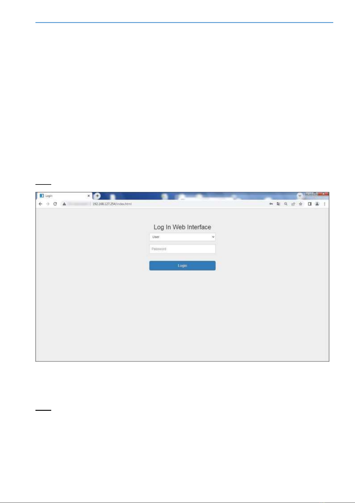
At the loading login form, proceed as follows (Fig.3):
•Enter http://192.168.127.254 or http://192.168.127.253 in the browser address bar.
•Choose User from drop-down menu as your access level
•Enter the default password: 222222
Note. Factory Installer is a username for technical support personnel only.
Fig.3. Example of a login form for radio with even serial number (192.168.127.254)
After successful login a window with a web interface with the main tab Operational Status will
be opened.
Note. The web interface window operates for each radio separately. To configure the wireless
channel (sides A and B of wireless radiolink), you will need to open two web interface windows like
on Fig.3, one for the radio on side A and a second window for the radio on side B.

MobiBridge-10G Web Interface Guide
7
OPERATIONAL STATUS TAB
The Operational Status tab provides information about the radio's operating mode and the
presence of an active wireless connection (Fig.4).
Fig.4. Operational Status tab
•The Signal Quality indicator shows whether the modem is working normally for this radio.
Green light means the wireless connection between both radios is established, while red
light means no connection. Current RSL value corresponds Signal Quality indicator.
•The Max Data Rate parameter displays the current bandwidth of the communication
channel.
•The 10GbE Link indicator shows whether the radio is connected to any active 10GbE
network equipment. In the normal operation within network, this indicator should be green.
If the is no connection to LAN, this indicator will be red.
•The System Uptime is a timer which counts uptime for this radio since last boot.
•The group of parameters within Modem box describes the modem operation. These
parameters are mostly for your information and for technical support.
•The RFMs box displays temperature value for chips and PCB boards both for Tx and Rx.
RFMs in this context is a block of beamformer registers that are applied as RF blocks.
•The Set1G and Set10G buttons set the 1Gigabit Ethernet or 10Gigabit Ethernet network
connection modes for the data communications port (SFP) to external network equipment.
MobiBridge-10G Web Interface Guide
8
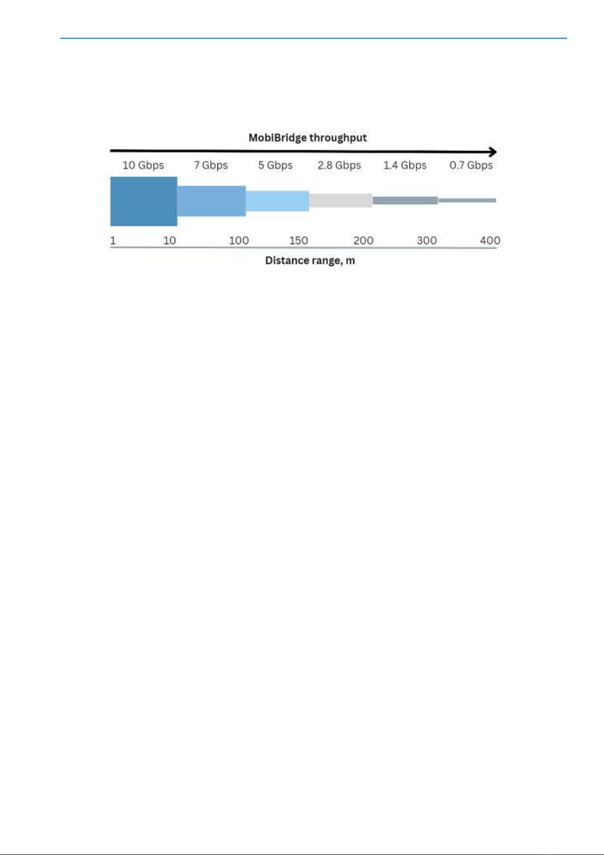
•The Long-range operation mode switch enables the highest transmitter signal gain and
receiver sensitivity to enable connection over 10 m distance. Maximum 10 Gbps throughput
is guaranteed at MobiBridge-10G operating ranges from 0.5 m to 10 m, with radios’
maximum range of up to 400 m (see Figure 5).
Fig.5. Throughput vs. Distance diagram for MobiBridge-10G radio
To configure the MobiBridge-10G operation mode for the wireless link (sides A and B), it is firstly
recommended to open a similar second web-interface window for another radio and check the
setting of the fixed connection rate mode for both radios. To do this, in the Current ACMB row,
select FIX mode from the Adaptive/FIX drop-down list. Click the Set button to make the fixed
link rate mode active. The signal quality indicator may briefly turn red during setup. Repeat the
procedure for the second radio.
Then press the SearchMode button to set the optimal modem mode. Repeat the procedure for
the second radio.
Press the SweepBeam button to automatically select the best angle of the built-in antenna
beam for the best signal quality. Repeat the procedure for the second radio.
If you plan to use both radios as a fixed wireless line (not for installation on vehicles), select
adaptive modulation for the highest data rate. To do this, from the Adaptive/FIX drop-down
list, select Adaptive mode and press the Set button to make the adaptive link rate mode active.
The signal quality indicator may briefly turn red during setup. Repeat for the second PPC.
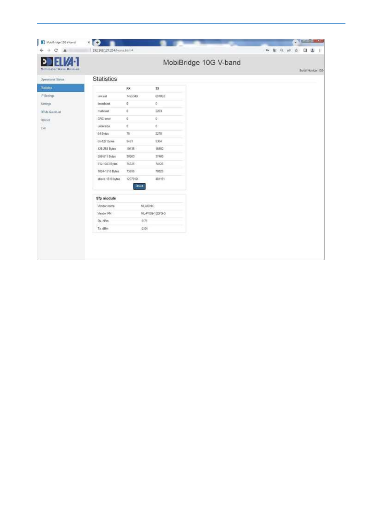
STATISTICS TAB
The Statistics tab collects information about the operation of this radio link, the data is
accumulated at a frequency of once per second.
If the admin wants to test the operation of the radio link, then should first reset the packet counters
with the Reset button, and then conduct a test of a certain duration (for example, 24 hours).
After that, evaluate the statistics to analyze how many packets and what type of packets were
transmitted through the interface.
The Statistics tab is a useful tool in case of radio link diagnostics. Having of statistics by packet
size, type, etc. helps to analyze the wireless connection performance with the help of such tools.
MobiBridge-10G Web Interface Guide
9
The
Fig.6. Statistics tab
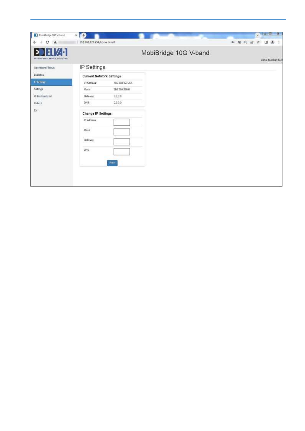
IP SETTINGS TAB
On the IP Settings tab you can set IP parameters for this radio. These settings have to be settled
for each radio separately.
Change IP address of this radio from default to actual one. For this, choose IP Settings tab in
left menu (Fig.6). Enter the IP parameters of your choice (could use default Mask 255.255.255.0
and default Gateway 0.0.0.0). Click Save button.
After changing the IP address, this new address will automatically appear in the browser address
bar, so that the administrator can continue to work with the web interface of this radio.
Save the new IP addresses for both radios in a secure file or a cloud password manager, or simply
write them down on paper to make sure that new IP addresses will not be forgotten.
MobiBridge-10G Web Interface Guide
10
Fig.7. IP Settings tab
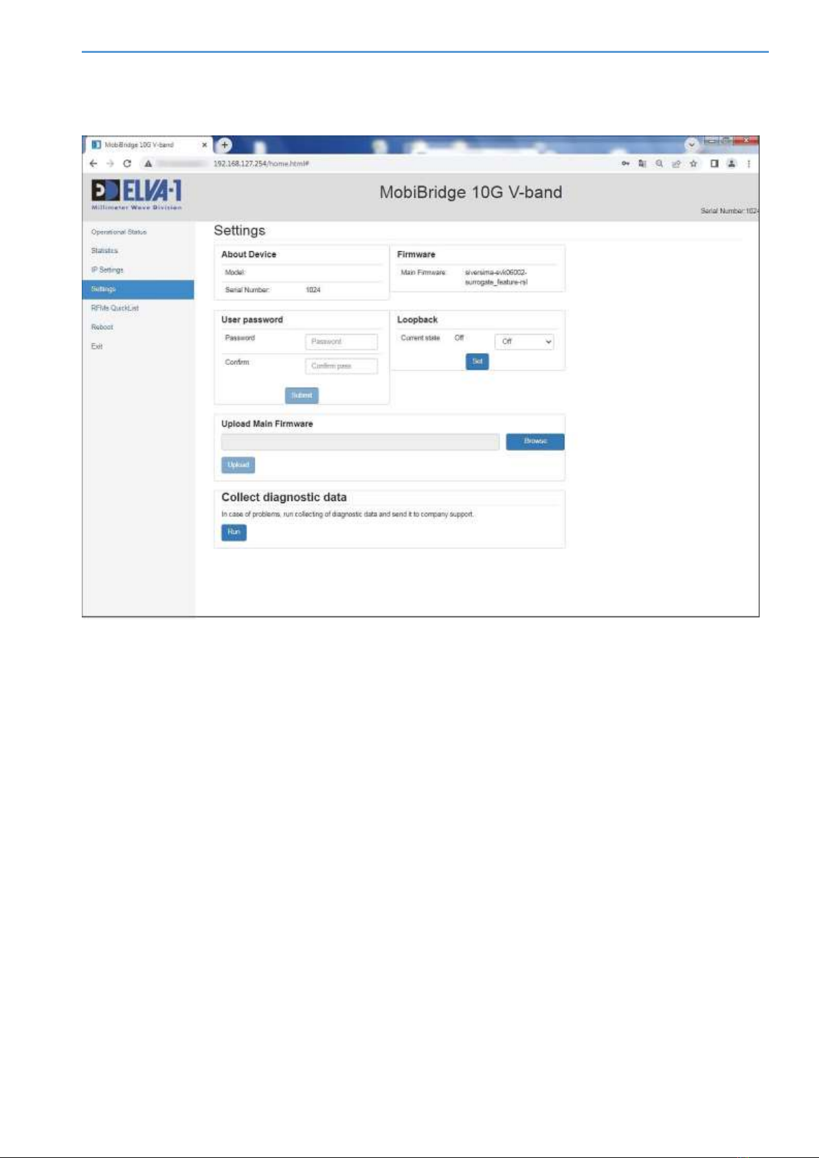
SETTINGS TAB
On the Settings tab you can set unique User password for this radio. The password has to be
settled for each radio separately. You can use uppercase and lowercase letters, numbers and
special characters. Enter new password, also confirm it, then press Submit button.
About Device is the info-box about this radio, also Firmware box displays current version of
Firmware.
In the Loopback box, you can set the modes OFF by default, or select from a drop-down list
either Line mode to test the optical cable from the external active network equipment to the
MobiBridge or Terminal mode.
Loopback mode is useful for link failure troubleshooting or when installing the device on a wireless
path. The mode allows you to independently test different sections of traffic route.
Loopback mode has different configurations:
•Line, where traffic coming over the optical cable to the radio unit is not passed to the
wireless, but is looped back. In this way, the admin can check the optical section from the
server room to the radio unit at the installation site, taking into account all sockets and
connections.
•Terminal, where all traffic that came over the wireless channel is not transmitted to the
optics, but is wrapped back to the wireless channel.
By selecting these modes, the administrator can check the sections of traffic passing sequentially.
For example: first check the optical line on side A, without affecting the radio channel and the
MobiBridge-10G Web Interface Guide
11
optics on side B. Then check the optics on side A and the radio channel, without touching the optics
of B. Then do the same thing from side B.
Fig.8. Settings tab
The Upload Main Firmware section allows to update the firmware. To do this,
•Upload the firmware to your computer, then select that file using the Browse button.
•Then click the Upload button, and the firmware will be updated for this radio. Repeat the
firmware update procedure for the other radio.
The Collect diagnostics data section is for Mobibridge 10G manufacturer's technical support
personnel only. To collect the data for support team, the Administrator follows additional
instructions from the manufacturer's technical support.
RFMS QUICKLIST TAB
On the RFMs QuickList tab you can set the sub-bands of operating frequencies for the receiver
and transmitter, as well as change the angle of rotation of the built-in antenna (to be performed
for each radio separately).
Since the wireless connection realized by Mobibridge-10G is a full duplex channel, the transmitter
and receiver work on different frequency channels. There is no hard bundle of duplex frequency
diversity in the product. On the contrary, the flexibility of frequency channel configuration is
realized. The administrator has the ability to choose which frequency channels will be used.

MobiBridge-10G Web Interface Guide
12
In total, Mobibridge-10G has 6 frequency channels. In different countries it may be allowed to use
from 3 frequency channels to all 6 frequency channels available in the radios. Thus, on the RFMs
QuickList tab the administrator can select the desired frequency plan and use it in the device.
Fig.9. RFMs QuickList tab
Note. It is important to understand the mirror principle of frequency channel assignment. If, for
example, the frequencies Tx 61GHz; Rx 57GHz are set to radio on side A, the mirror variant Tx
57GHz; Rx 61GHz must be selected to the radio on side B.
The antenna beam angle is rotated in manual mode. The Beam TX (Transmitter Beam) and Beam
RX (Receiver Beam) fields are used for this purpose. Beam shifting using these settings can help
to increase the data rate when the orientation of the Mobibridge-10G faceplates to each other is
largely inconsistent. Then the antenna pointing can be adjusted using these software controls.
REBOOT AND EXIT
By selecting the menu item Reboot in the left menu, the Host controller is restarted and the
firmware of all chips and modules is reloaded, with new settings applied. Each radio can be
rebooted independently of the operation of the other radio.
When selecting the Exit menu item in the left menu, the web interface session is terminated for
this radio and access to it is closed. To re-enter the web interface, you will need to re-type the
current login and password. The operation of the web interface of the given radio is terminated
independently of the operation of the web iinterface of another responding radio.
***
For any inquiries regarding the web interface, please contact ELVA-1 by email
support@elva-1.com.
Table of contents


 user manual")


