Elvaco CMa12w User manual

CMa12w C1 Users Manual English– Version 4
CMa12w C1 Users Manual
English
1050068-CMa12w Wireless M-Bus
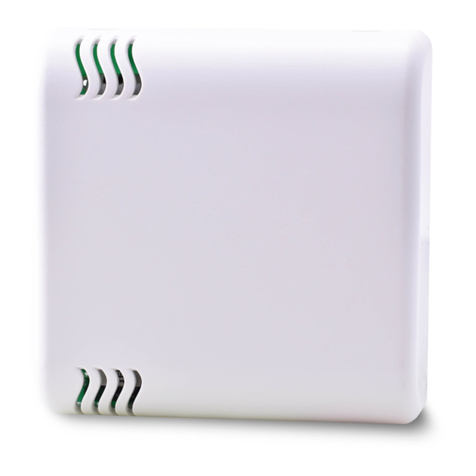
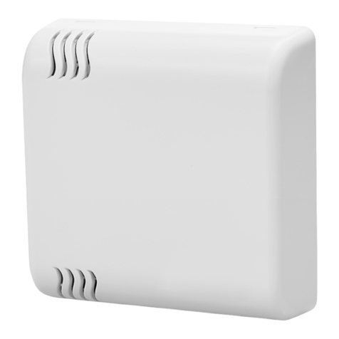
CMa12w is a wireless M-Bus communicating
temperature sensor for indoor use. CMa12w complies
with OMSstandard and uses wireless M-Bus mode C1.
CMa12w is the perfect choice when wiring is not an
option.

CMa12w C1 Users M anua
l English
CMa12w C1 Users M anual English
page |
2
(
22
)
2016
-
03
-
07
Document id:
1090081
Version
4
Contents
CONTENTS ............................................................................................................ 2
1DOCUM ENT NOTES .................................................................................... 4
1.1 COPYRIGHT AND TRADEM ARK ......................................................................................... 4
1.2 CONTACTS ..................................................................................................................... 4
2USING THIS M A NUA L ................................................................................. 5
2.1 PURPOSE AND AUDIENCE................................................................................................ 5
2.2 MODELS ........................................................................................................................ 5
2.3 ADDITIONAL AND UPDATED INFORM ATION....................................................................... 5
3INTRODUCTION........................................................................................... 6
3.1 PRODUCT CONFIGURATION ............................................................................................. 6
3.2 CAPABILITIES ................................................................................................................. 6
3.3 APPLICATIONS................................................................................................................ 6
4GETTING STA RTED ..................................................................................... 7
4.1 OVERVIEW ..................................................................................................................... 7
4.2 MOUNTING .................................................................................................................... 9
4.3 WIRELESS M-BUS.......................................................................................................... 9
4.3.1 Installation procedure ............................................................................................... 9
4.3.1.1 Installation procedure – Select Unencrypted m ode...................................... 9
4.3.1.2 Installation procedure – Select Encrypted mode........................................... 9
5A PPLICA TION DESCRIPTION .................................................................... 11
5.1 OPERATION .................................................................................................................. 11
5.1.1 Operation m odes..................................................................................................... 11
5.1.1.1 Inactive mode...............................................................................................11
5.1.1.2 Installation procedure...................................................................................11
5.1.1.3 Normal operation – Unencrypted mode ......................................................11
5.1.1.4 Normal operation – Encrypted mode...........................................................11
5.2 LED INDICATIONS ........................................................................................................ 12
6A DM INISTRA TION OF THE PRODUCT ...................................................... 13
6.1 M-BUS PRODUCT IDENTIFICATION ................................................................................. 13
WIRELESS M-BUS MODE .......................................................................................................... 13
6.2 M-BUS ADDRESSING .................................................................................................... 13
6.3 OPERATION M ODE ........................................................................................................ 13
6.4 SPONTANEOUS TRANSM ISSION .................................................................................... 13
6.5 TELEGRAM FORM AT ..................................................................................................... 13
6.5.1 Send spontaneous data (SND_NR)........................................................................ 13
6.5.1.1 Slave to master – Telegram 1 (SND_NR)......................................................13
7TROUBLESHOOTING ................................................................................. 16
7.1 COLLECTOR DOES NOT RECEIVE ANY TELEGRAM SENT FROM THE PRODUCT .................... 16
7.2 VALUES ARE INACCURATE............................................................................................. 16
8TECHNICA L SPECIFICA TIONS .................................................................. 17

CMa12w C1 Users M anua
l English
CMa12w C1 Users M anual English
page |
3
(
22
)
2016
-
03
-
07
Document id:
1090081
Version
4
8.1 CHARACTERISTICS ........................................................................................................ 17
9TYPE A PPROVA LS .................................................................................... 18
10 SA FETY A ND ENVIRONM ENT ................................................................... 19
10.1 SAFETY PRECAUTIONS.................................................................................................. 19
11 DOCUM ENT HISTORY ............................................................................... 20
11.1 DOCUMENT SOFTWARE AND HARDWARE APPLIANCE...................................................... 20
12 REFERENCES ............................................................................................. 21
12.1 REFERENCES ................................................................................................................ 21
12.2 TERM S AN D ABBREVIATIONS......................................................................................... 21
12.2.1 Num ber representation........................................................................................... 21
13 A PPENDIX A – EXA M PLE ......................................................................... 22
13.1 DENOMINATION OF VALUES IN REPORTS........................................................................ 22
13.2 DENOMINATION OF VALUES FOR USE IN FILTERS ............................................................ 22

CMa12w C1 Users M anua
l English
CMa12w C1 Users M anual English
page |
4
(
22
)
2016
-
03
-
07
Document id:
1090081
Version
4
1Document notes
All information in this manual, including product data, diagrams, charts, etc. represents
inform ation on products at the time of publication, and is subject to change w ithout prior
notice due to product improvem ents or other reasons. It is therefore recommended that
customers contact Elvaco AB for the latest product information before purchasing a
CMa12w product.
The docum entation and product are provided on an “as is” basis only and m ay contain
deficiencies or inadequacies. Elvaco AB takes no responsibility for damages, liabilities or
other losses by using this product.
1.1 Co p y ri g h t an d t r ad em ar k
© 2015, Elvaco AB. All rights reserved. No part of the contents of this manual may be
transmitted or reproduced in any form by any means without the written permission of
Elvaco AB. Printed in Sweden.
CMa12w is a trademark of Elvaco AB, Sw eden.
1.2 Co nt ac t s
Elvaco AB Headquarter
Teknikgatan 18
434 37 Kungsbacka
SWEDEN
Phone: +46 300 30250
Fax: +46 300 18440
E-Mail: info@elvaco.com
Elvaco AB Technical Support
Phone: +46 300 434300
E-Mail: support@elvaco.com
Online: http://www.elvaco.com

CMa12w C1 Users M anua
l English
CMa12w C1 Users M anual English
page |
5
(
22
)
2016
-
03
-
07
Document id:
1090081
Version
4
2Using this manual
2.1 Pu r po se an d au d i en c e
This m anual covers information needed to mount, configure and use the CM a12w, trådlös
Wireless M-Bus indoor temperature sensor. It is intended for field engineers and
developers.
2.2 M od el s
CMa12w
2.3 A d d it io n al and updat ed inf orm at i o n
Latest documentation version is available on Elvaco web site at http://www.elvaco.com.

CMa12w C1 Users M anua
l English
CMa12w C1 Users M anual English
page |
6
(
22
)
2016
-
03
-
07
Document id:
1090081
Version
4
3Introduction
3.1 Pr o du c t c o n f i g u r at i o n
See Table 1 Product configuration, to find out the capabilities of your product.
Pr o d uc t
nam e
Com m ent s
CMa12w Indoor Wireless M -Bus temperature sensor
Table 1 Product configuration
3.2 Capab ili t ies
CMa12w is a 1-way wireless M-Bus communicating temperature sensor for indoor use.
CMa12w is the ideal product for com fort level billing. The high accuracy sensor and user
friendly handling make the CMa12w the perfect choice for tenant owners.
3.3 A p p l i c at i o ns
The CMa12w should be used in the following scenarios:
Indoor measurement of temperature
Used instead of a CMa10/CMa11 when wiring is not an option
Used instead of a CMa10w/CMa11w when humidity does not need to be measured

CMa12w C1 Users M anua
l English
CMa12w C1 Users M anual English
page |
7
(
22
)
2016
-
03
-
07
Document id:
1090081
Version
4
4Getting Started
This chapter covers the steps required for getting the CM a12w installed and operational.
4.1 Ov erv i ew
1
2
3
Figure 3
4
DOWN
5
Figure 3
1. LED1
2. Push button (SW1)
3. Label with product
inform ation, serial number
(identification), hardware
revision and
article number
4. Do not use for
mounting
5. Do not use for
mounting

CMa12w C1 Users M anua
l English
CMa12w C1 Users M anual English
page |
8
(
22
)
2016
-
03
-
07
Document id:
1090081
Version
4
Fig ure 3 Dem oun tin g

CMa12w C1 Users M anua
l English
CMa12w C1 Users M anual English
page |
9
(
22
)
2016
-
03
-
07
Document id:
1090081
Version
4
4.2 M o un t i n g
When mounting the CM a12w, avoid rooms with a lot of supplementary heat, such as
kitchens or south facing rooms. Position the sensor away from direct sunlight. Avoid
placing on an external wall or near an external door. M ake sure that the sensor is not
positioned closer than 1 m from the nearest radiator and at least 1.5 m above the floor.
CMa12w can be mounted directly on the w all, or over a mounting box Ø70 mm. If the
product is placed over a conduit pipe, it is recommended to fill the pipe to prevent air flow
which could affect accuracy of the values.
Remove the rear cover to be able to press the installation button SW1 (4).
IM PORTA NT
Please take the following in consideration:
Do not use mounting holes (6) as in Figure 3 .
Turn the rear cover as shown in Figure 3 .
Do not mount the product inside a steel cabinet, which will dramatically lower the
possibilities to connect to a collector.
4.3 Wi rel ess M -Bu s
The product is delivered with the radio turned off. The radio must be manually switched on
during the installation procedure.
Th e pr o d uc t w il l not be act ivat ed unt i l t he in st allat io n pr oc edure i s st art ed .
4.3.1 In st allat io n p r o c ed ure
The product can be installed and enabled in two modes:
U n en c ry p t ed m o d e: Data is sent unencrypted and the encryption key is not
needed to decrypt the data.
En c ry p t ed m o de: Data is sent in encrypted m ode and the encryption key is
needed to decrypt the data.
Please advise your project m anager which operation mode is used in your project.
4.3 .1 .1 In st al lat i o n p r oc edu re – Sel ec t U nen c r yp t ed m o d e
By performing the following steps, the product will start to send spontaneous
u n en c ry p t ed data:
1. Press and hold button SW1 (4) for 5-10 seconds until LED1 (3) flashes quickly. See
Table 2 for more inform ation about LED indications.
2. Release SW1 (4)
The product will now start to send spontaneous unencrypted SND_NR telegrams every 30
seconds.
4.3 .1 .2 In st al lat i o n p r oc edu re – Sel ec t En cr y p t ed m od e
By performing the following steps, the product will start to send spontaneous en c r y pt ed
data:
1. Press and hold button SW1 (4) for 12-25 seconds, LED1 (3) changes from flashing
quickly to flashing slowly. See Table 2 for more inform ation about LED indications.
2. Release SW1 (4)

CMa12w C1 Users M anua
l English
CMa12w C1 Users M anual English
page |
10
(
22
)
2016
-
03
-
07
Document id:
1090081
Version
4
3. The product will now start to send spontaneous encrypted SND_NR telegram s every 30
seconds.
IM PORTA NT
Pl ease t ak e t he f ol low in g i n co nsi der at io n:
A f t er t h e p r od uc t i s ac t i v at ed , t h e en c ry p t i on m o de c an n ot be c h ang ed .
Th e pr o d u ct m u st b e sen t t o El v ac o t o b e u n lo c k ed .

CMa12w C1 Users M anua
l English
CMa12w C1 Users M anual English
page |
11
(
22
)
2016
-
03
-
07
Document id:
1090081
Version
4
5Application description
This chapter covers general application description and configuration of the product.
5.1 Oper at i on
The product will autom atically, after the installation procedure, send C1 messages every
3rd minute containing sensor data, such as instantaneous temperature. The product will
also send product status information, containing battery status and other relevant
inform ation.
5.1.1 Op erat i o n m o d es
The product has the following operation m odes:
1. Inactive (on delivery)
2. Installation procedure (during installation)
3. Norm al operation - unencrypted mode
4. Norm al operation - encrypted mode
5.1 .1 .1 In ac t iv e m o d e
The product is delivered inactive, which means that the product does not perform any
tasks before an installation procedure is started. This saves the battery lifetime and
ensures that there is no radio activity until the product is manually activated.
5.1 .1 .2 In st al lat i o n p r oc edu re
The installation procedure is used to activate the product, see 4.3.1.
5.1 .1 .3 N o r m al op er at i o n – U n en c ry p t ed m o d e
In normal operation unencrypted mode, the product will by default send spontaneous
u n en c ry p t ed m essages every 3rd minute. This mode is normally used when the collector
or AMR/AMM system does not handle AES encryption or if the AES key is unknown to the
host system .
5.1 .1 .4 N o r m al op er at i o n – En c ry p t ed m o d e
In normal operation encrypted mode, the product will by default send spontaneous
en cr y p t ed m essages every 3rd minute. This m ode is used to secure data sent from the
product to the collector or AMR/AMM system. To be able to decrypt the data, the private
128 bit AES key must be known by the collector or by the host system. The private 128 bit
AES key is on demand provided to the customer by Elvaco AB.
IM PORTA NT
Th e c u st o m er c an no t c han ge enc r y pt i o n m o de /o per at i o n m o d e. Th e p r od u c t
m u st b e sen t t o Elv ac o t o be u nl o c k ed .

CMa12w C1 Users M anua
l English
CMa12w C1 Users M anual English
page |
12
(
22
)
2016
-
03
-
07
Document id:
1090081
Version
4
5.2 LED in d icat i ons
LED 1 St at e/Desc r i p t i on V i su al
Perm anently off Off
Fast flash
100 ms on/100 ms
off
Triggered when button is
pressed for 5-10 seconds to
select unencrypted operation
mode. Releasing the button in
this state will select
unencrypted operation mode.
Slow flash
800 ms on/800 ms
off
Triggered when button is
pressed for 12-25 seconds to
select encrypted operation
mode. Releasing the button in
this state will select encrypted
operation mode.
Table 2 LED 1 indications

CMa12w C1 Users M anua
l English
CMa12w C1 Users M anual English
page |
13
(
22
)
2016
-
03
-
07
Document id:
1090081
Version
4
6Administration of the product
This chapter covers the configuration and Wireless M-Bus implementation of the product.
The product follows the new M-Bus standard EN13757-2, EN13757-3, EN13757-4.
6.1 M -Bus produ c t i dent i f ic at i on
The product can be identified by the following information:
Manufacturer string = ELV
Medium = 0x1B (Room sensor)
Generation = 30-39 (CM a12w),
The generation field between product releases will onl y change (increase by 1) if
the M -Bus protocol information changes between versions. Use the software
version field in the M -Bus telegram to identify current software version.
Wi r el ess M -Bus m ode
The product is using Wireless M-Bus mode C1-b, which m eans that the product sends
spontaneous data in one direction, from product to collector.
6.2 M -Bu s add r essi ng
The address used is a globally unique address, which is set during production.
6.3 Oper at i on m ode
The product can operate in encrypted or unencrypted mode. In encrypted mode, a 128 bit
AES key is used for all telegrams.
6.4 Spo n t an eo u s t ran sm i ssio n
The product will automatically start sending spontaneous telegrams with measurement
data after the installation procedure is completed. The product sends by default an
SND_NR telegram every 3rd minute.
6.5 Tel egram f or m at
All data in the tables are described unencrypted.
6.5.1 Sen d spo n t an eo us d at a (SND _NR)
During normal operation, the wireless M-Bus command SND_NR is sent by default every
3rd minute. Telegram type is type B, wireless M -Bus mode C1.
6.5 .1 .1 Sl av e t o m ast er – Telegr am 1 (SND _N R)
By t e i n dex D at a D esc r i pt i o n
0x55 preamble
0x55 preamble
0x55 preamble
0x55 preamble
0x54 sync word byte 0

CMa12w C1 Users M anua
l English
CMa12w C1 Users M anual English
page |
14
(
22
)
2016
-
03
-
07
Document id:
1090081
Version
4
0x3D sync word byte 1
0x54 sync word byte 2
0x3D sync word byte 3
0 0xnn L-field
1 0x44 C-field: SND_NR =0x44
2..3 0x9615 Manufacturer
“ELV”
4..7 0xnnnnnnnn Identification number
8 0x1E Version field
9 0x1B Product type (m edium ) = room sensor
10 0x7A 0x7A = "short application header"
11 0xnn access number, increases after every TX
0...255
12 0xnn Status. Bit 2 (0x04) is "low battery flag", bit
3 (0x08) is "sensor fault flag".
Default is STATUS = 0x00
13..14 0xnnnn CONFIG:
Bit 7..4 = 0 or 2, = number of encrypted 16
byte block, 0 if encryption = OFF
Bit 11..8 = encryption mod, = 5 with
encryption, 0 without encryption
15 0x2F Decryption verification byte 1
16 0x2F Decryption verification byte 2
17 DIF 16-bit integer = 0x02 or 0x32 at sensor error
18 VIF 0x65 = "external tem perature" in "centi
celsius"
19..20 0xnnnn Instantaneous temperature x 100
At sensor error, the temperature will be set
to 0x0000
21 DIF 16-bit integer" = 0x42 or 0x72 at sensor
error
22 VIF 0x65 = "external temperature" in "centi
celsius"
23..24 0xnnnn 1h average temp x 100
Or at error, the temperature will be set to
0x0000
25 DIF 0x02 (16 bit integer)
26 VIF 0xFD
27 VIFE 0x1B
28..29 0xnnnn Battery status
Bit9 Bit8
--------------------------
1 1 = 3 bars on LCD (CMa10W 100%)
1 0 = 2 bars on LCD
0 1 = 1 bars on LCD
0 0 = 0 bars on LCD
Bit 0: 1 = Sensor fault

CMa12w C1 Users M anua
l English
CMa12w C1 Users M anual English
page |
15
(
22
)
2016
-
03
-
07
Document id:
1090081
Version
4
30 0x0d Firmware version DIF
31 0xfd Firmware version VIF
32 0x0f Firmware version VIFE = “ Other software
version”
33 0x05 Length of firmw are string (varying)
34..38 0xnnnnnnnnnn Firmware version string in form at:
Major.Minor.PatchLevel
39 0x0F End of telegram, no more data.

CMa12w C1 Users M anua
l English
CMa12w C1 Users M anual English
page |
16
(
22
)
2016
-
03
-
07
Document id:
1090081
Version
4
7Troubleshooting
7.1 Co l l ec t o r d oes n ot r ec ei v e an y t el eg r am sen t f r o m t h e p r od u c t
This can be due to the following reasons:
Make sure that the product has been turned on during the installation by pressing
the button SW1 quickly. LED1 flashes at unencrypted mode and is quickly
illuminated at encrypted m ode. If this does not occur, see, section 4.3.1 for
operation/activation.
The master is not pow ered up or not correctly configured.
The distance to the m aster is not within range.
The master antenna is not properly mounted for best performance.
The product is mounted inside a m etallic cabinet or is disturbed by other radio
equipment.
7.2 V al u es ar e i n ac c u r at e
The temperature sensor is very accurate, but incorrect positioning of the product m ay
result in unintended temperature variation. Please take the follow ing in consideration
when mounting the product:
Do not mount the product close to heat sources (front and rear)
Do not mount the product in direct sunlight
Do not mount the product in the area of a spotlight beam
If the problem persists, please contact Elvaco AB.

CMa12w C1 Users M anua
l English
CMa12w C1 Users M anual English
page |
17
(
22
)
2016
-
03
-
07
Document id:
1090081
Version
4
8Technical specifications
8.1 Ch ar ac t er i st i c s
Ty p e V al ue U n i t Co m m en t s
Mechanics
Material ABS UL94-V0 - White
Protection class IP20 -
Dim ensions 80 x 80 x 28 mm
Weight 75 g
Antenna wireless M -Bus Internal -
Mounting Wall
mounted
Electrical
Power supply Battery - Lifetime 15 years at 15-25 °C
Environm ental
Operating temperature range -10 to +50 °C
Storage temperature range -40 to +85 °C
Operating humidity 0 to 95 %RH No condensation
Accuracy sensor
Temperature range -20 to +55 °C
Temperature +5 to +55 °C +/- 0.2 °C Typical tolerance
Temperature -20 to 55 °C +/- 0.4 °C Typical tolerance
User interface
Green LED Yes - Configuration/Activation
Push button Yes - Configuration/Activation
Wireless M-Bus
M-Bus standard EN 13757-4 - Mode C1-b
M-Bus com m ands SND_NR -
Momentary values Temperature - Instantaneous and average
over hour
Historic values Average
values for
last hour
-
Transmit power 10 mW
Sensitivity -102 dBm Reception not activated
Frequency 868 MHz Band
Tabel 3 Technical specifications

CMa12w C1 Users M anua
l English
CMa12w C1 Users M anual English
page |
18
(
22
)
2016
-
03
-
07
Document id:
1090081
Version
4
9Type approvals
CMa12w is designed to comply with the directives and standards listed below.
A p p r ov al D esc r i pt i o n
EMC EN 61000-6-2, EN 61000-6-3
Table 4 Approvals

CMa12w C1 Users M anua
l English
CMa12w C1 Users M anual English
page |
19
(
22
)
2016
-
03
-
07
Document id:
1090081
Version
4
10 Safety and environment
10.1 Saf et y prec aut i on s
The following safety precautions m ust be observed during all phases of the operation,
usage, service or repair of CM a12w. Users of the product are advised to convey the
following safety information to users and operating personnel and to incorporate these
guidelines into all manuals supplied with the product. Failure to comply with these
precautions violates safety standards of design, manufacture and intended use of the
product. Elvaco AB assumes no liability for customer’s failure to com ply with these
precautions.
All instructions must be carefully read before CMa12w is installed and used. They contain
important inform ation about how the product is used properly.
The installation of CMa12w should not be started before the technical specifications are
fully understood. The work must be perform ed in the order listed in this manual, and only
by qualified personnel. The work must also be done in accordance w ith national electrical
specifications and applicable local regulations.
In order to avoid the product being damaged by static electricity, an ESD wristband should
be worn when handling the product.
The labelling of the product may not be changed, removed or made unrecognizable.

CMa12w C1 Users M anua
l English
CMa12w C1 Users M anual English
page |
20
(
22
)
2016
-
03
-
07
Document id:
1090081
Version
4
11 Document history
V er si o n D at e D esc r i pt i o n A u t h or
1.0 2015-01-09 First release Carl-Henrik Carlsson
11.1 D oc um ent sof t w are an d h ardw are appl iance
Ty p e V er si o n Dat e Co m m en t s
Hardware R1A 2014-10-23
Software 3.0.3 2014-10-23
Other manuals for CMa12w
2
Table of contents
Other Elvaco Temperature Controllers manuals
