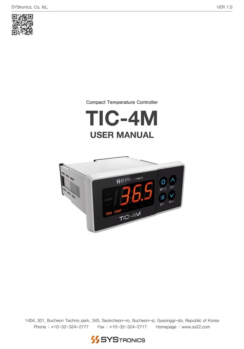
ILX Lightwave LDT-5412B User manual

User’s Guide
Thermoelectric Temperature Controller
LDT-5412B
700474 March 2013
ILX Lightwave Corporation · 31950 Frontage Road · Bozeman, MT, U.S.A. 59715 · U.S. & Canada: 1-800-459-9459 · International Inquiries: 406-556-2481 · Fax 406-586-9405
ilx.custhelp.com ·www.newport.com/ilxlightwave


March 2013 i LDT-5412B
Table of Contents
Safety Information and the Manual............................................................................ iii
General Safety Considerations.................................................................................. iii
Safety Symbols ......................................................................................................... iv
Warranty.....................................................................................................................v
Limitations ..................................................................................................................v
Returning an Instrument ............................................................................................ vi
Claims for Shipping Damage........................................................................................................... vi
Comments, Suggestions, and Problems .................................................................. vii
Chapter 1: Introduction and Specifications .................................................1
Safety Considerations ................................................................................................1
Initial Inspection..........................................................................................................1
Product Overview .......................................................................................................2
Options and Accessories............................................................................................3
Specifications .............................................................................................................4
Chapter 2: General Operation.....................................................................5
Grounding Requirements ...........................................................................................5
AC Line Power Requirements ....................................................................................5
The Power Up Sequence ...........................................................................................5
Connections ...............................................................................................................6
Front Panel Operation ................................................................................................7
Power On / Off..................................................................................................................................8
I LIMIT Knob .....................................................................................................................................8
Setpoint Adjustment Knob................................................................................................................8
Display Mode and 7 Segment LED Display .....................................................................................8
Error Indicators .................................................................................................................................8
Output Off/On Button........................................................................................................................9
General Operating Procedures...................................................................................9
Warm-Up and Environmental Considerations..................................................................................9

March 2013 ii LDT-5412B
General Guidelines for Sensor Selection and Safety Limits ..........................................................10
Sensor Options...............................................................................................................................10
General Operation....................................................................................................13
Chapter 3: Troubleshooting.......................................................................15
Troubleshooting Guide .............................................................................................16

March 2013 iii LDT-5412B
Safety and Warranty Information
Details about cautionary symbols
Safety markings used on the instrument
Information about the warranty
Customer service contact information
Safety Information and the Manual
Throughout this manual, you will see the words Caution and Warning indicating potentially
dangerous or hazardous situations which, if not avoided, could result in death, serious or minor injury,
or damage to the product. Specifically:
Caution indicates a potentially hazardous situation which can result in minor or moderate injury or
damage to the product or equipment.
Warning indicates a potentially dangerous situation which can result in serious injury or death.
General Safety Considerations
If any of the following conditions exist, or are even suspected, do not use the instrument until safe
operation can be verified by trained service personnel:
Visible damage
Severe transport stress
Prolonged storage under adverse conditions
Failure to perform intended measurements or functions
If necessary, return the instrument to ILX Lightwave, or authorized local ILX Lightwave distributor, for
service or repair to ensure that safety features are maintained.
All instruments returned to ILX Lightwave are required to have a Return Authorization Number
assigned by an official representative of ILX Lightwave Corporation. See Returning an Instrument for
more information.

March 2013 iv LDT-5412B
Safety Symbols
This section describes the safety symbols and classifications.
Technical specifications including electrical ratings and weight are included within the manual. See
the Table of Contents to locate the specifications and other product information. The following
classifications are standard across all ILX Lightwave products:
Indoor use only
Ordinary Protection: This product is NOT protected against the harmful ingress of
moisture.
IEC Class I Equipment (grounded type)
Mains supply voltage fluctuations are not to exceed ±10% of the nominal supply voltage.
Pollution Degree II
Installation (overvoltage) Category II for transient over-voltages
Maximum Relative Humidity: <85% RH, non-condensing
Operating temperature range of 10 °C to 40 °C
Storage and transportation temperature of –40 °C to 70 °C
Maximum altitude: 3000 m (9843 ft.)
This equipment is suitable for continuous operation.

March 2013 v LDT-5412B
Safety Marking Symbols
This section provides a description of the safety marking symbols that appear on the instrument.
These symbols provide information about potentially dangerous situations which can result in death,
injury, or damage to the instrument and other components.
Caution, refer
to manual
Earth ground
Terminal Alternating current
Visible and/or
invisible laser
radiation
Caution, risk of
electric shock
Protective
Conductor
Terminal
Caution,
hot surface
Frame or chassis
terminal
Warranty
ILX Lightwave Corporation warrants this instrument to be free from defects in material and
workmanship for a period of one year from date of shipment. During the warranty period, ILX will
repair or replace the unit, at our option, without charge.
Limitations
This warranty does not apply to defects caused by abuse, modifications, or to use of the product for
which it was not intended.
This warranty is in lieu of all other warranties, expressed or implied, including any implied warranty of
merchantability or fitness for any particular purpose. ILX Lightwave Corporation shall not be liable for
any incidental, special, or consequential damages.
If a problem occurs, please contact ILX Lightwave Corporation with the instrument's serial number,
and thoroughly describe the nature of the problem.

March 2013 vi LDT-5412B
Returning an Instrument
If an instrument is to be shipped to ILX Lightwave for repair or service, be sure to:
Obtain a Return Authorization number (RA) from ILX Customer Service.
Attach a tag to the instrument identifying the owner and indicating the required service or
repair. Include the instrument serial number from the rear panel of the instrument.
Attach the anti-static protective caps that were shipped with the instrument.
Place the instrument in the original packing container with at least 3 inches (7.5 cm) of
compressible packaging material. Shipping damage is not covered by this warranty.
Secure the packing box with fiber reinforced strapping tape or metal bands.
Send the instrument, transportation pre-paid, to ILX Lightwave. Clearly write the return
authorization number on the outside of the box and on the shipping paperwork. ILX
Lightwave recommends you insure the shipment.
If the original shipping container is not available, place your instrument in a container with at
least 3 inches (7.5 cm) of compressible packaging material on all sides.
Repairs are made and the instrument returned transportation pre-paid. Repairs are warranted for the
remainder of the original warranty or for 90 days, whichever is greater.
Claims for Shipping Damage
When you receive the instrument, inspect it immediately for any damage or shortages on the packing
list. If the instrument is damaged, file a claim with the carrier. The factory will supply you with a
quotation for estimated costs of repair. You must negotiate and settle with the carrier for the amount
of damage.

March 2013 vii LDT-5412B
Comments, Suggestions, and Problems
To ensure that you get the most out of your ILX Lightwave product, we ask that you direct any
product operation or service related questions or comments to ILX Lightwave Customer Support. You
may contact us in whatever way is most convenient:
Phone: (800) 459-9459 or (406) 586-1244
Fax: (406) 586-9405
On the web at: http://www.newport.com/locations/brandcontacts.aspx?brandid=19
Or mail to:
ILX Lightwave Corporation
31950 East Frontage Road
Bozeman, Montana, U.S.A 59715-8642
www.newport.com/ilxlightwave
When you contact us, please have the following information:
Model Number
Serial Number
End-user Name
Company
Phone
Fax
Description of what is connected to the ILX Lightwave instrument
Description of the problem
If ILX Lightwave determines that a return to the factory is necessary, you are issued a Return
Authorization (RA) number. Please mark this number on the outside of the shipping box.
You or your shipping service is responsible for any shipping damage when returning the instrument
to ILX Lightwave; ILX recommends you insure the shipment. If the original shipping container is not
available, place your instrument in a container with at least 3 inches (7.5 cm) of compressible
packaging material on all sides.
We look forward to serving you even better in the future!

March 2013 viii LDT-5412B

March 2013 1 LDT-5412B
Chapter 1:
Introduction and Specifications
This chapter is an introduction to the LDT-5412B Thermoelectric Temperature Controller.
Safety Considerations and unpacking information
Product Overview
Options and accessories
Specifications
Safety Considerations
If any of the following symptoms exist, or are even suspected, remove the LDT-5412B
from service. Do not use the LDT-5412B until trained service personnel can verify safe
operation.
Visible damage
Severe transport stress
Prolonged storage under adverse conditions
Failure to perform intended measurements or functions
If necessary, return the LDT-5412B to ILX Lightwave for service and repair to ensure that
safety features are maintained.
Initial Inspection
When you receive your LDT-5412B Thermoelectric Temperature Controller, verity that the following
items were shipped with the instrument
LDT-5412B Thermoelectric Temperature Controller Manual
Power Cord

March 2013 2 LDT-5412B
Product Overview
The LDT-5412B is a thermoelectric temperature controller capable of stably and accurately
controlling thermoelectric mounts in low power applications. This is achieved by modulating the
current through a thermoelectric load and continuously monitoring the feedback signal
generated from a thermistor temperature sensor. The linear output stage of the LDT-5412B
offers the low current noise necessary to achieve the temperature stability required in most low-
noise and frequency-stabilized laser applications.
Features of the LDT-5412B include:
Long term temperature stability of ±0.01 °C
Linearized thermistor mode allows temperature readout accurate to ±1°C with specific 10 k
thermistors
Bipolar 6 Watt linear output stage
PI control loop with adjustable P gain and fixed I gain
12 Volt bias for operating external fans
Buffered analog measurement output
If cleaning is required, use a clean dry cloth. Do not use solvents.
Figure 1.1 – LDT-5412B Front Panel

March 2013 3 LDT-5412B
Figure 1.2 – LDT-5412B Rear Panel
Options and Accessories
Options and accessories available for LDT-5412B Thermoelectric Temperature Controller include the
following:
DESCRIPTION MODEL / PART NUMBER
Temperature Controller Interconnect Cable (terminated with 9-pin DSUB) CC-505S
Temperature Controller Interconnect Cable (unterminated) CC-501S
Calibrated 10 kThermistor TS-510
Uncalibrated 10 kThermistor TS-520
Uncalibrated 5 kThermistor TS-521
Uncalibrated 20 kThermistor TS-523
Uncalibrated 100 kThermistor TS-525
Unipolar Control Adapter UCA-350
TO-Can Laser Diode Mount LDM-4405
TO-Can Laser Diode Mount LDM-4407
C-Mount Laser Diode Mount LDM-4409
TO-Can Laser Diode Mount (with optional collimating lens) LDM-4412
TELECOM Series Laser Diode Mount LDM-4980
Production Line TO-Can Laser Diode Mount LDM-4990

March 2013 4 LDT-5412B
Specifications

March 2013 5 LDT-5412B
Chapter 2:
General Operation
This chapter is an overview of the operation of the LDT-5412B Thermoelectric Temperature
Controller.
Power requirements
Front panel operation
General operating procedures
Grounding Requirements
The LDT-5412B Thermoelectric Temperature Controller comes with a three conductor AC power
cable. The power cable must be plugged into an approved three-contact electrical outlet or used
with a three-contact to two-contact adaptor with the grounding wire connected to an electrical
ground (safety ground). ILX Lightwave recommends connecting the instrument only to properly
earth grounded receptacles. The power cord connector and provided power cable meet IEC
safety standards.
AC Line Power Requirements
The LDT-5412B Thermoelectric Temperature Controller features a universal input and can be
operated at nominal line voltages of 90 - 240 VAC and 50 – 60 Hz.
The Power Up Sequence
Prior to power up ensure that the ventilation holes located on the left and right hand side
as well as on the top of the instrument have no obstructions that would impede airflow.
With the LDT-5412B connected to an AC power source, pressing POWER supplies AC line power to
the instrument. After power-up, make sure that the OUTPUT is off (LED unlit) until you have
configured the instrument for your application.

March 2013 6 LDT-5412B
Connections
Temperature Control Output: A 15-pin D-Subminiature connector is located on the back panel of
the instrument. The connections for each terminal are shown below.
LDT-5412B
PIN NUMBER CONNECTION
1 TE Module (+)
2 TE Module (+)
3 TE Module (-)
4 TE Module (-)
5 External Setpoint
6 External Setpoint
7 Sensor (+)
8 Sensor (-)
9 Analog Ground
10 Control Signal
11 N/C
12 N/C
13 N/C
14 Fan (+)
15 Fan (-)
Figure 2.1 – LDT-5412B Output Connector
The TE drive current is available at the 15 pin connector. Pins 1 and 2 and pins 3 and 4 are tied
together internally. Pins 1 and 2 source current while cooling and sink current while heating. Pins 3
and 4 sink current while cooling and source current while heating.
An NTC Thermistor is required to sense the load temperature and must be connected between pins
7 and 8.
An external resistor may be used to control the setpoint resistance; this resistor must be connected
between pins 5 and 6. The SET RESISTANCE switch must be in the EXT position in order to use
the external resistor as a setpoint, otherwise the setpoint is controlled by the front panel knob.
The control signal on pin 10 provides approximately a 1 V/A signal referenced to pin 9, which can be
used to drive an isolated booster current supply.
Pins 14 and 15 provide the ability to power an external fan through the 15-pin DSUB connector.
This circuit can provide up to 100 mA at a nominal voltage of 12 VDC. This feature includes
current limiting and over-power shutdown for the external fan.

March 2013 7 LDT-5412B
THERMISTOR MODE: A three position switch that adjusts the measurement and setpoint current
sources and also determines how the values are displayed on the front panel. The 10µA and 100µA
positions configure the sensor current source for the selected value and displays the value of the
setpoint and current sensor in kon the front panel. °C LINEARIZED FOR 10kis a special mode
that places a 10 kresistor in parallel with the thermistor to linearize the temperature response. The
front panel is calibrated to display the approximate temperature with an accuracy of ±1.0 °C in °C
when a 10 kthermistor is used as the sensor.
SET RESISTANCE: Allows the operator to bypass the set resistance function of the front panel and
externally control to a known resistance. When the switch is in the EXT position, the temperature is
controlled to match the resistance measured between pins 5 and 6 of the OUTPUT connector. This
mode is useful if always operating at the same setpoint. When the switch is in the INT position, the
external resistor is ignored and the front panel knob controls the temperature setpoint.
ANALOG OUTPUT: An isolated BNC connector is located on the rear panel of the LDT-5412B that
provides the capability to externally measure the voltage at the thermistor terminals. The nominal
gain of this connection is 10 mV/kin the 10 µA range and 100 mV/kin the 100 µA range. In the
linearized operating mode the voltage present at this connection mirrors the voltage present across
the parallel combination of the thermistor and a 10 kresistor with 100 µA passing through the
combination. The nominal output impedance of this connection is 2 k.
GAIN: A single turn potentiometer which adjusts the control loop gain. This adjustment affects the
slew rate and settling time of the LDT-5412B when reaching the desired setpoint. If the GAIN is set
too low (counter-clockwise,) the LDT-5412B will take longer to reach the desired setpoint. If the
GAIN is set too high (clockwise,) the LDT-5412B may oscillate around the desired setpoint. To
adjust, use a small blade screwdriver.
Front Panel Operation
This section describes the fundamentals of operation for the LDT-5412B Thermoelectric
Temperature Controller. The order of descriptions will follow the normal progression of how the user
would typically configure the instrument for use for the first time.
Figure 2.2 – LDT-5412B Front Panel

March 2013 8 LDT-5412B
Power On / Off
The POWER button applies power to the LDT-5412B.
I LIMIT Knob
The current LIMIT knob allows the user to set the upper limit of the output current. The user may
adjust the output current from zero (LIMIT knob turned fully counterclockwise CCW) to 2 Amps
(LIMIT knob turned fully clockwise CW). This LIMIT knob is recessed to prevent accidental
readjustment of the output current during operation.
The LIMIT current value is not displayed, but the adjustment is linear. For example, setting the
LIMIT knob half-way between 0 and 2 Amps will limit the output current to 1 Amp. A more
accurate LIMIT setting may be attained by the following procedure:
1. Connect a short between pins 2 and 3 of DB15 (TE OUTPUT connector on rear panel). Connect
a 10 kresistor across pins 7 and 8 of DB15.
2. Set the DISPLAY MODE switch to TE CURRENT. Turn the OUTPUT switch on (LED lit). Adjust
the Main Control Knob fully counter-clockwise (CCW).
3. Adjust the LIMIT control until the display reads the desired limit current. Turn the OUTPUT off,
remove the short from pins 2 and 3 of DB15, and remove the resistor form pins 7 and 8 of DB15.
During operation the TE output current is unconditionally limited to the value set by the LIMIT
adjustment
Setpoint Adjustment Knob
The Setpoint Adjustment knob is located on the upper right side of the LDT-
5412B front panel and is used to set the desired operating, or setpoint,
resistance or temperature of the load. The setpoint may be set from 0.00k
to ~20.00kwhen the instrument is in the 10µA Sensor Mode (see
SENSOR MODE below), from 0.0kto ~200.0kin the 100µA mode and
from approximately 10°C to 70°C but will only meet the stated accuracy
specification when set between 10°C and 40°C (see LINEARIZED MODE
below). Rotating the knob clockwise in 10/100 µA mode will increase the
resistance (decrease the temperature) and rotating counterclockwise will decrease the resistance
(increase the temperature). When the LDT-5412B is in °C LINEARIZED FOR 10krotating the
knob counter clockwise will increase the temperature and when rotating clockwise will decrease the
temperature. This is due to the negative temperature coefficient of NTC thermistors where in a
decrease in resistance represents an increase in temperature.
Display Mode and 7 Segment LED Display
Using the button located under the DISPLAY MODE will allow the user to cycle between ACTUAL,
SET, and TEC CURRENT on the 7 segment LED display. When the ACTUAL LED is illuminated the
display reads the measured resistance or temperature (linearized mode) of the thermistor, the SET
LED when illuminated displays the set point resistance or temperature (linearized mode), and when
the TE CURRENT LED is illuminated the LDT-5412B will display the actual measured TEC current.
Error Indicators
TEC OPEN: Indicates that the thermoelectric voltage exceeds the rated compliance voltage of the
instrument. The output must be on to enable monitoring of TEC OPEN. Detection of a TEC OPEN

March 2013 9 LDT-5412B
state will shut the output off. The indicator will remain illuminated after a fault until the output is
enabled or power is cycled. In some instances a TEC OPEN fault may occur with high impedance
TECs and can be remedied by reducing the current limit as to reduce the maximum voltage
generated.
SNS OPEN: Indicates that the thermistor or external setpoint resistance has exceeded 50 kwhen
the 100 µA or Linearized sensor mode is selected, or 500 kwhen the 10 µA sensor mode is
selected. Like the TEC OPEN indicator, the output must be on to enable monitoring of SNS OPEN.
Detection of a SNS OPEN state will shut the output off. The indicator will remain illuminated after a
fault until the output is enabled or power is cycled.
I LIMIT: This LED indicates that the current output is limited by the limit setpoint. It is normal for this
indicator to illuminate shortly after turning the output on, or when load power changes significantly. If
the indicator stays on or occasionally turns on after a long period, the controller cannot maintain
temperature due to the power requirements of the load. Changing the temperature setpoint, or
increasing the current limit, if it is safe to do so, can fix this problem.
Output Off/On Button
The OUTPUT off/on switch is located in the lower right-hand corner of the front panel. This
switch has a toggling action which turns the output current of the LDT-5412B off and on. When
the output is active, the LED indicator just above the switch will be lit.
When the OUTPUT is off, it is safe to connect or disconnect sensitive devices from the LDT-
5412, even though the power supply is on. The OUTPUT is off when AC power is first applied to
the instrument. Additionally, there are three other conditions which will automatically cause the
output to reset to the off state:
• Power Drop-outs - AC line power drop-outs lasting more than about 1 second will trigger an
internal power monitor and cause the output to switch unconditionally to the off state. This
sequence is also initiated when the LDT-5412B is switched off or unplugged.
• SNS OPEN - If the externally connected thermistor or set point resistor is open, the output is
switched to the off state and the SNS OPEN LED indicator is illuminated.
• TEC OPEN – If the connected TEC exceeds the rated voltage of the LDT-5412B the output will
be disabled and the TEC OPEN LED will be illuminated.
If any of these conditions occur and the OUTPUT turns off; output may be turned on again by
first correcting the cause of the fault and then pressing the OUTPUT off/on switch.
General Operating Procedures
The discussion below presents guidelines for operation as well as some common operating
procedures.
Warm-Up and Environmental Considerations
To achieve the rated accuracy, allow the LDT-5412B to warm-up for at least one hour before use.
Operate the controller within the environmental limits specified in Chapter 1.

March 2013 10 LDT-5412B
General Guidelines for Sensor Selection and Safety Limits
This section presents some guidelines to assist in selecting the optimal settings for your
application.
Sensor Options
The LDT-5412B Thermoelectric Temperature Controller can measure resistance of a thermistor
and display the output either in resistance or a calculated temperature. When the rear panel
switch is set to 100 µA or 10 µA the LDT-5412B will display resistance. When the rear panel
switch is set to °C LINEARIZED FOR 10kthe LDT-5412B will display a calculated
temperature.
Thermistor Range
Thermistors can span a wide temperature range, but their practical range is limited by their non-
linear resistance properties. As the sensed temperature increases, the resistance of the
thermistor decreases significantly and the thermistor resistance changes less for an equivalent
temperature change, therefore the thermistor becomes less sensitive. Consider the temperature
and sensitivity figures in Table 2.2.
Table 2.2 Thermistor Sensitivity Values
Temperature Sensitivity
-20 °C 5600 /°C
25 °C 439 /°C
50 °C 137 /°C
In the LDT-5412B the practical upper temperature limit is the temperature at which the
thermistor becomes insensitive to temperature changes. The lower end of the temperature
range is limited by the maximum input voltage of the LDT-5412B. Thermistor resistance and
voltage are related through Ohms Law (V = I x R). The LDT-5412B supplies current to the
thermistor, either 10 µA or 100 µA, and as the resistance changes, a changing voltage signal is
available to the thermistor inputs of the LDT-5412B. The LDT-5412B will over-range when the
input voltage exceeds about 2.0 Volts. The maximum temperature ranges for a typical 10 k
thermistor (a 10 kthermistor has a resistance of 10 kohms at 25 °C) are given in Table 2.3
below.
Table 2.3 Temperature Ranges (10 kThermistor)
Temperature Sensitivity
10 µA -37 °C to over +60 °C
100 µA +8 °C to over +100 °C
Selecting and Using Thermistors
The type of thermistor you choose will depend primarily on the operating temperature range.
From Figure 2.3 you can also see that 10 kthermistors are generally a good choice for most
laser diode applications where high stability is required at near room temperatures. Similarly, 5
kthermistors are often a good choice for detector cooling applications where you want to
operate at temperatures from -30 °C to room temperature. Much higher or lower temperature
ranges can be controlled through the use of higher or lower resistance thermistors. For more
Table of contents
Other ILX Lightwave Temperature Controllers manuals

ILX Lightwave
ILX Lightwave LDT-5910 User manual
ILX Lightwave
ILX Lightwave LDT-5900 Series User manual
ILX Lightwave
ILX Lightwave LDT-5416 User manual
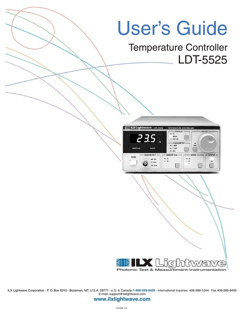
ILX Lightwave
ILX Lightwave LDT-5525 User manual
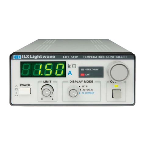
ILX Lightwave
ILX Lightwave LDT-5412 User manual
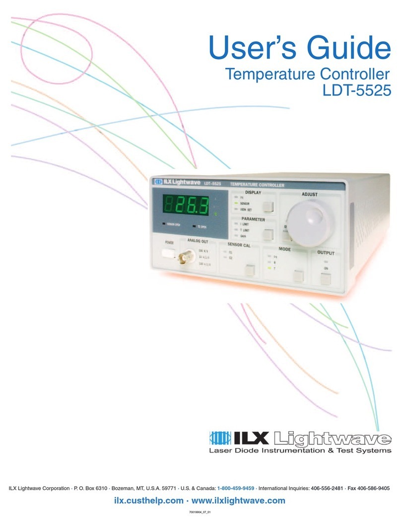
ILX Lightwave
ILX Lightwave LDT-5525 User manual
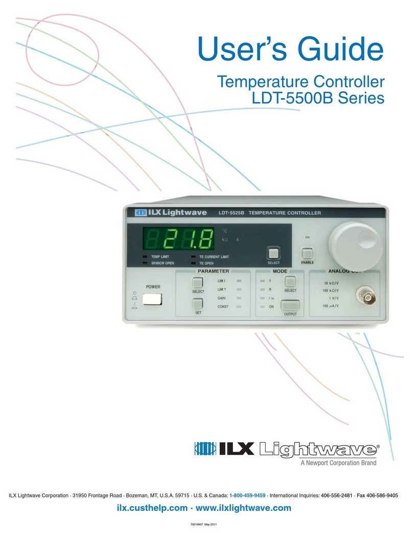
ILX Lightwave
ILX Lightwave LDT-5500B Series User manual
