Elvo E911D User manual
ELVO E911D/E911A/E912A 1
ELVO
SOLDERING STATIONS
INSTRUCTION MANUAL
ELVO.010.5001.E
Pb-Sn
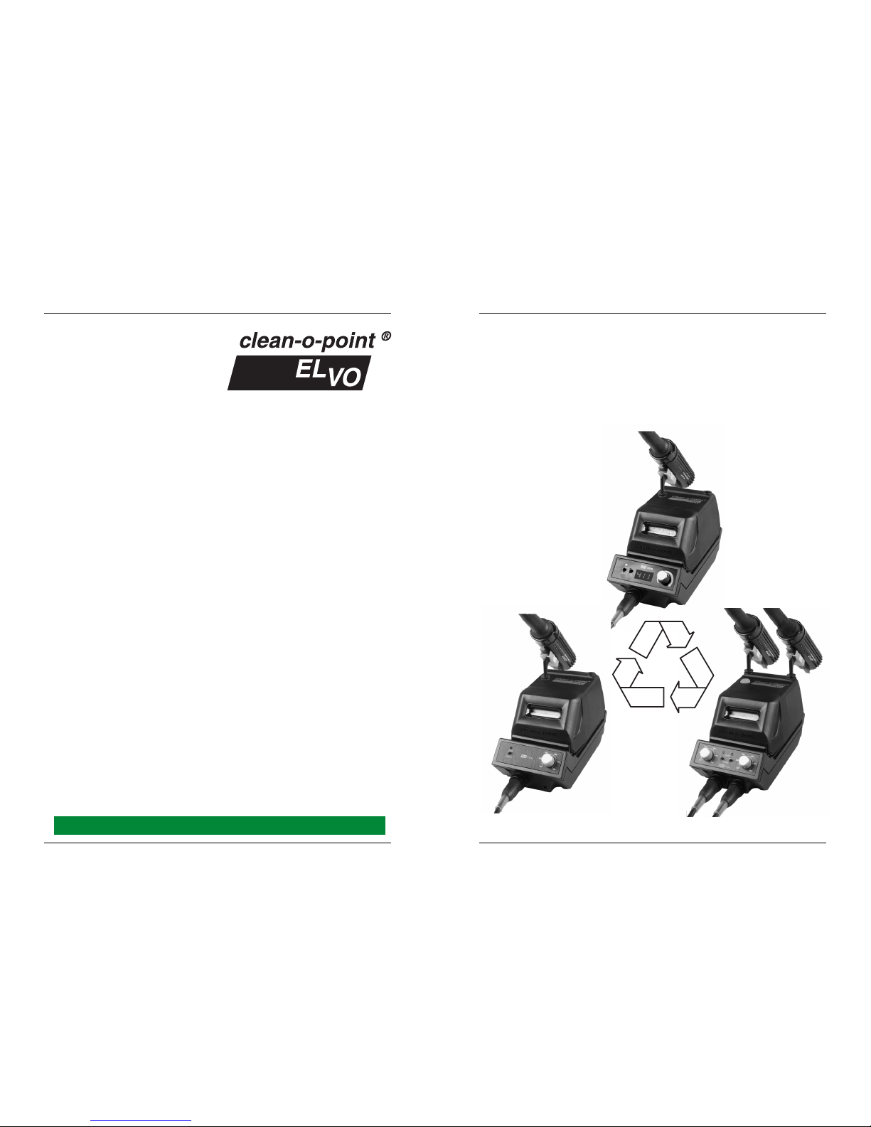
E912A
E911A
E911D
32 ELVO E911D/E911A/E912A
Switzerland
ELVO ELECTRONICS AG
Hauptstrasse 93
CH-2552 Orpund
Tel: ++41
/
(0)32
/
356 04 31
Fax:++41
/
(0)32
/
356 04 32
I: www.elvo.ch
The future belongs to quality and excellence
2ELVO E911D/E911A/E912A
INTRODUCTION
0
Warranty
The equipment has been carefully tested both
mechanically and electrically prior to shipment.
It has also been verified, as far as possible, that
the equipment is in good working order. For a
period of 12 months (6 months if the equipment
operates day and night, even if only occasion-
ally), beginning on the day the equipment is
ready to be shipped at our plant (in cases where
we undertake assembly and/or initial operation,
from the day of initial operation), we guarantee
good working of the equipment delivered and
we promise to repair or replace at will, as quickly
and reasonably as possible, any parts which
are proven to be faulty in design, material or
workmanship. If, during operation and within
the period of warranty, any discrepancy appears
between the equipment contracted for and the
one actually supplied by us, we shall bear the
costs incurred in repairing or replacing the faulty
parts at our plant. We shall supply and ship at
our expense "FOB factory" the replacement
material necessary for carrying out the repairs
under this warranty on the site. We shall pay
the salary and wages of our employees, but the
buyer shall pay for the travelling time, as well
as their transportation and out of pocket ex-
penses.
Our liability is limited to direct damages.
Our warranty shall not cover replacements or
repairs which are due to normal wear and tear,
faulty or negligent maintenance, disregard of
operating instructions in this manual, overload-
ing, use of unsuitable materials, faulty construc-
tion of buildings, incorrect assembly work, faulty
electrical connections, acts of God, and any
other cause beyond our control.
Our "General Terms and Conditions of Sale",
of which the above text is an excerpt, are bind-
ing for all warranty cases.
This document, its contents, and the technology described are strictly
confidential. It is provided for assistance to ELVO customers only. It
may not be copied, repro-duced or passed on to third parties with-
out express, written permission from ELVO ELECTRONICS.
Dear customer
We thank you for selecting one of our ELVO
clean-o-point®
soldering stations, the new
standard in soldering technology. The solder-
ing stations answer the need for increased qual-
ity control in the soldering process. With the
hundred thousands of clean-o-point®
tip clean-
ers sold in the past number of years all over the
world, satisfied customers urged us to integrate
this extraordinary tip cleaning system into these
new stations.
Please read the operating instructions carefully
to maximize the advantages of using your new
soldering station.
Responsibility for shipment
The moment the equipment is shipped from our
plant, the buyer assumes all risks regarding it,
in particular but not limited to the risk for dam-
age, loss, theft or confiscation. We are liable
only for damages which can undeniably be
traced to gross negligence of our personnel.
Inspection of goods upon arrival
Remove packing material carefully and keep it
for possible storing or return of the unit.
After unpacking, check the equipment for pos-
sible damage due to transportation. Should this
be the case, inform immediately both the for-
warder and the carrier. The buyer must exam-
ine the equipment within a reasonable period
of time and notify us immediately in writing of
any defects. Failing such notification the equip-
ment is deemed to be accepted.
ELVO E911D/E911A/E912A 31
Subject to change without notice.
Printed in Switzerland
ZUMBACH Electronic AG
P.O. Box
CH-2552 Orpund
December 2006
ELVO E911D/E911A/E912A 3
13
4
7
2
10
5
7
E911D
9
8
12
10
2
11
14
▼
1
▼
6
4
3
9
8
14
▼
10
11
2
6
12
1
▼
14
▼
1
9
8
E911A
E912A
4
6
11
7
▼
30 ELVO E911D/E911A/E912A
S
SAFETY CAUTIONS 9
SERVICING 19
Spare Parts 19, 21
Sponges 12, 18, 19, 21
T
Technical data 8
Temperature 4, 7, 8, 13, 14
Temperature range 8, 13
Temperature Stability 13
Tip Replacement 17
TIP SELECTOR CHART 17, 20
W
Working place overview 11
Working Temperature 13
4ELVO E911D/E911A/E912A
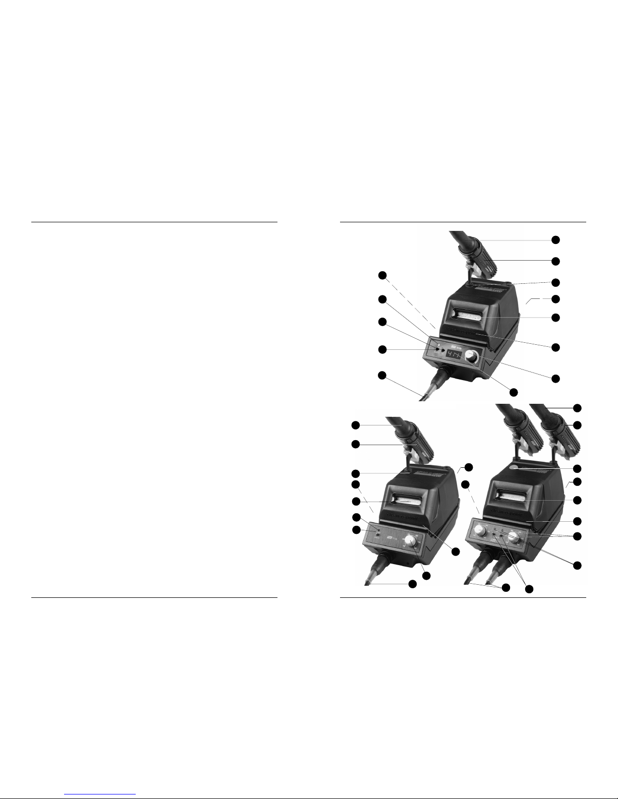
Legend
Main switch
Potentiometer for electronic temperature adjustment
"SET" tumbler switch
"Heater/Stand-by" tumbler switch
Digital read-out (with E911D only)
"Heater" LED heating control lamp
Temperature resistant silicon-cable
Iron holder
Soldering iron with high-efficency ceramics heating element and removable sol-
dering tips (for tip selector chart see chapter 6.1)
clean-o-point®
Automatic patented soldering tips cleaning system.
The motorized moist sponge rollers are self-cleaning.
Round motorized sponge rollers
Stop/Go switch
Automatic for E911D and E911A
The self-cleaning motorized round sponges are only beginning to work when
soldering iron is taken out of holder.
Standard switch
Manual for E912A
Connector socket (24 V) for mains supply unit
1
2
3
4
5
6
7
8
9
10
11
12
13
14
ELVO E911D/E911A/E912A 29
INDEX
10
A
ACCESSORIES 21
ADDRESSES 20, 25
B
Block diagram 22, 23, 24
C
Care of tips 16
Clean-o-point 2, 4, 7, 12, 15, 16, 18
Cleaning 2, 4, 7, 15, 16, 18, 19
Components Assembly 12
D
Dimensioned drawing 8
E
ESD 10, 11, 12, 19
F
Features 7, 9, 12
G
General Cleaning 16
M
Maintenance 2, 15, 16, 18
Mains protection 10
MOS 7, 10, 13
O
Operation 2, 12, 13,
P
Product Features 7
R
Recycling 18, 28

ELVO E911D/E911A/E912A 5
CONTENTS
2
1PRODUCT DESCRIPTION 7
1.1 PRODUCT FEATURES ................................................................ 7
1.2 TECHNICAL DATA TYPE E911D / E911A / E912A .................... 8
1.3 DIMENSIONED DRAWING .......................................................... 8
3INITIAL OPERATION 12
3.1 GENERAL FEATURES ............................................................... 12
3.1.1 Feature Description ................................................................ 12
3.2 COMPONENTS ASSEMBLY ..................................................... 12
3.3 TEMPERATURE RANGE ........................................................... 13
3.3.1 Temperature Stability .............................................................. 13
3.3.2 Working Temperature ............................................................. 13
3.4 OPERATING INSTRUCTIONS ................................................... 14
3.4.1 clean-o-point®- How it works .............................................. 15
SAFETY CAUTIONS 9
2.1 SAFETY INFORMATION .............................................................. 9
2.2 SAFETY CAUTIONS .................................................................... 9
2.3 OPERATING PRECAUTIONS ...................................................... 9
2.4 MECHANICAL PRECAUTIONS ................................................ 10
2.5 ELECTRICAL PRECAUTIONS .................................................. 10
2.6 MAINS PROTECTION ............................................................... 10
2.7 THE ESD WORKING PLACE..................................................... 10
2.7.1 ESD - Working place overview .................................... 11
!
▲
!
▲
!
▲
!
▲
!
▲
!
28 ELVO E911D/E911A/E912A
RECYCLING
9
9.1 GENERAL RECYCLING
All individual components of the unit described in this manual have to be
treated according to the local regulations for recycling (batteries, metals
etc.) or for safe disposal ( printed circuit boards etc).
Pb-Sn
6ELVO E911D/E911A/E912A
6ACCESSORIES 21
6.1 SOLDERING TIPS ...................................................................... 21
6.2 SPARE SPONGES ..................................................................... 21
DIAGRAMS 22
7.1 BLOCK DIAGRAM E911D ......................................................... 22
7.2 BLOCK DIAGRAM E911A ......................................................... 23
7.3 BLOCK DIAGRAM E912A ......................................................... 24
7
8ADDRESSES 25
8.1 THE ELVO SALES-AND SERVICE SUPPORT .......................... 25
RECYCLING 28
9.1 GENERAL RECYCLING ............................................................ 28
INDEX 29
9
10
4MAINTENANCE 16
4.1 GENERAL CLEANING ............................................................... 16
4.2 CARE OF TIPS ........................................................................... 16
4.3 TIP REPLACEMENT AND DRESSING ..................................... 17
4.3.1 Commissioning of New Tips ............................................... 17
4.4 CLEAN-O-POINT®MAINTENANCE ......................................... 18
5SERVICING 19
5.1 RETURN FOR REPAIRS ............................................................ 19
5.2 CONDITIONS APPLYING TO SPARE PARTS........................... 19
5.3 SPARE PARTS LIST ................................................................... 20
ELVO E911D/E911A/E912A 27
Sweden Cyncronica AB
Tomtbergavägen 2
SE-14567 Norsborg
Tel ++46
/
853 194 300
Fax ++46
/
853 194 310
Filtronic AB
Box 2284
Hissgatan 2
SE-531 40 Lidköping
Tel ++46
/
510 208 10
Fax ++46
/
510 210 40
Taiwan KINGYOUP ENTERPRISES CO.
4F-16., No.16, Lane 609, Sec. 5
Chung Hsin Road
TW-Taipei County
Tel ++886
/
2 999 17 50
Fax ++886
/
2 999 17 47
UK Link Hamson Ltd.
5 The Gateway Centre
Coronation Road
Cressex Bus Park
GB-High Wycombe HP12 3SU
Tel ++ 44
/
1494 439 786
Fax ++ 44
/
1494 526 222
USA ELVO Division of
Zumbach Electronics Corp.
140 Kisco Avenue
Mount Kisco, NY 10549-1412
Phone ++1
/
914 241 7080
Fax ++1
/
914 241 7096
e-mail: [email protected]
ELVO E911D/E911A/E912A 7
ELVO Electronics Temperature Controlled Soldering Stations Type E911D /
E911A / E912A with integrated Automatic Soldering Tip Cleaning are the new
high performance standard for soldering equipment.
•Soldering of electronic components with electric or thermic
sensitiveness like C-MOS-circuits, FET-transistors, LCD-read-outs
•Soldering with high requirements to the soldering connection,
Military, Aviation and Space research
•Soldering with special solder (high and low melting) and connection
within exact tolerances
1.1 PRODUCT FEATURES
•clean-o-point®
,automatic soldering tip cleaner
•Accurate, stable temperature setting and control
•Variable temperature control
from 140-450°C (280-850°F) for digital version
from 150-400°C (300-840°F) for analog version
•Rapid heat up and instant recovery
•Digital read-out models
•Zero-voltage thyristor power switching
•Ultra-low tip leakage
•Comply with DOD and ML Specs
PRODUCT DESCRIPTION
1
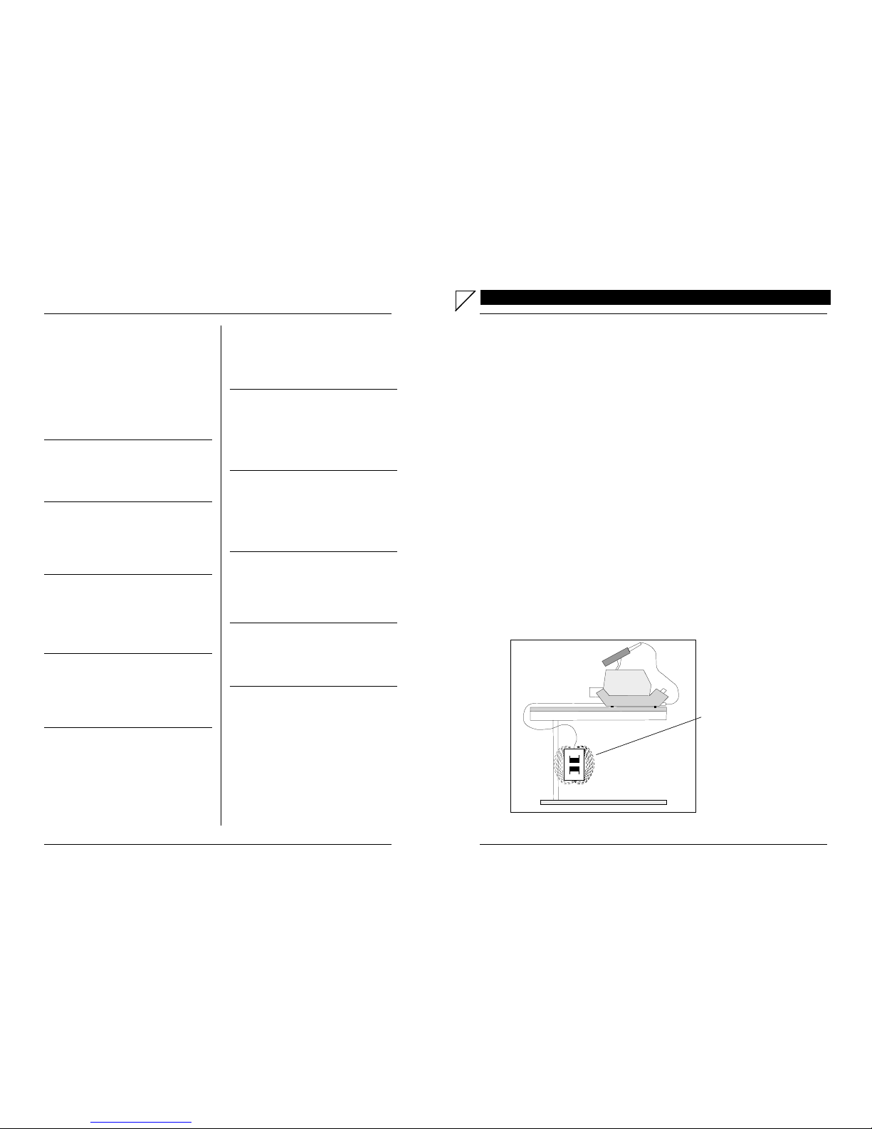
Mains supply unit:
Suspend outside the working
zone using the assembly kit
provided for this way you can
avoid most efficently any elec-
tromagnetic radiation.
26 ELVO E911D/E911A/E912A
Hungary Ferrumino
Királi utca 9
HU-1042 Budapest
Tel ++36 1 379 0417
Fax ++36 1 379 0418
Nóniusz Kft.
Köbanyai u. 47/b
HU-1101 Budapest
Tel ++36 1 350 4326
Fax ++36 1 350 6459
Italy COFILI MACCHINE
Via Privata Schiatti
I-20057 Vedano al Lambro / MI
Tel ++39
/
39 49 20 15
Fax ++39
/
39 49 15 79
Japan CLAY & COMPANY LTD
4-6-8 Kawara-Machi, Chuo-Ku
Osaka Kagaku Seni Kaikin 3a
J-Osaka City
Tel ++81
/
6 204 43 55
Fax ++81
/
6 204 43 62
Korea SE HAN Electools Ltd.
B-508-1, Bundang Techno Park
Yatap-dong 148, Bundang KU
Songnam. Kyonggi-DO
Korea 463-070
Tel ++82
/
2 277 48 72
Fax ++82
/
2 272 93 73
Malaysia Broad-line Corp. SDN BHD
25, Jalan Radin Anum 2
Seri Petaling
MY-57000 Kuala Lumpur
Tel ++65
/
3 9057 0091
Fax ++65
/
3 9059 3273
Netherlands Unitek Eapro
Schootensee Dreef 21
NL-5700 AD Helmond
Tel ++ 31
/
4925 42 225
Fax ++ 31
/
4925 36 222
Norway KREPRO AS
Bonsdalsvn. 32
Postboks 233
N-2070 Raholt
Tel ++ 47
/
639 953 320
Fax ++ 47
/
639 953 933
Philippines MVENT
Market Venture Philippines Inc.
523 Santissima Trinidad St.
San Antonio Valley 6
PH-1707 Paranoque City
Tel ++63
/
2 825 97 84
Fax ++63
/
2 825 43 44
Singapore CHIP HUA EQUIPMENT
AND TOOLS PTE Ltd.
701 Sims Drive
#02-04 LHK Building
SG-Singapore 337383
Tel ++65
/
6298 30 88
Fax ++65
/
6297 00 29
Slovakia Mikrona Mkroelektronické
Prvky Systémy
Ku Bratke 1
SK-93505 Levice
Tel ++421/
366 310 430
Fax ++421/
366 312 497
Slovenia Atech Elektronika
Bac pri Meteriji 30
SL-6242 Materija
Tel ++386/
568 000 01
Fax ++386/
568 742 441
Spain Bielec Electronics S.L.
Portugal Carme Karr, 13
E-08034 Barcelona
Tel ++34
/
932 802 989
Fax ++34
/
932 804 113
8ELVO E911D/E911A/E912A
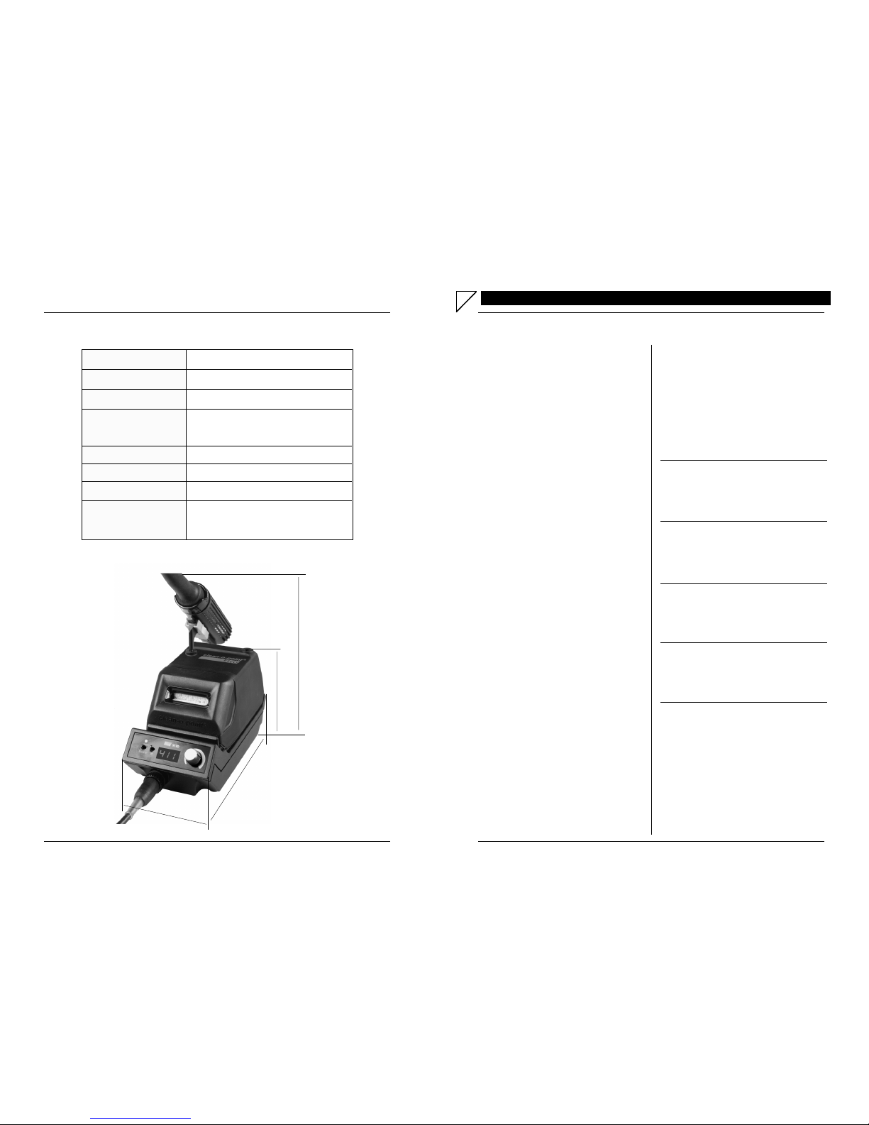
1.3 DIMENSIONED DRAWING
Power supply 115 or 230 V~, 50/60 Hz
Heater voltage 24 V
Power of iron (wattage) 55 W
Temperature range 140-450°C (280-850°F) digital
150-400°C (300-840°F) analog
Tip leakage < 2 mV
Standard Tip Type ET 4520 S 2.0
Dimensions See dimensioned drawing (below)
Weight Mains supply unit: 1.4 kg (3.09 lbs)
Soldering station: 1.1 kg (2.43 lbs)
1.2 TECHNICAL DATA TYPE E911D / E911A / E912A
Dimensions in mm (inch)
▲
98(3.86)
176(6.93)
▲
▲
▲
▲
91(3.58)
▲▲
189(7.44)
▲
ELVO E911D/E911A/E912A 25
ADDRESSES
8
8.1 THE ELVO SALES- AND SERVICE SUPPORT
Austria JI+C WarenvertriebsgesmbH
Theresianumgasse 13
A-1040 Wien
Tel ++43
/
1 812 27 39
Fax ++43
/
1 812 10 81
FAIR-TRADE
Mittelstrasse 63
A-2203 Manhartsbrunn
Tel ++43
/
224 583 9900
Fax ++43
/
224 583 9903
Belgium Arcoss BVBA
Bremheidelaan 8
B-2300 Tunrhout
Tel ++32
/
144 201 51
Fax ++32
/
144 225 51
Czech. ABE TEC s.r.o.
Republic Prumyslova 387
CZ-53003 Pardubice
Tel ++ 420
/
466 670 192
Fax ++ 420
/
466 655 127
Denmark Hin Horsen A/S
Langmarksvej 29
DK-8700 Horsen
Tel ++ 45
/
7625 90 90
Fax ++ 45
/
7625 90 91
France A. Jahnichen
38, Rue de Peupliers
F-92008 Nanterre Cedex
Tel ++33
/
1 47 86 84 40
Fax ++33
/
1 47 86 16 01
Germany Technisches Büro KULLIK &
Partner Vertriebs GmbH
Mettgenberg 3
D-58540 Meinerzhagen
Tel ++ 49
/
235 790 9510
Fax ++ 49
/
235 790 9595
Switzerland ELVO Electronics AG
(H.Q.) Hauptstrasse 93
CH-2552 Orpund
Schweiz
Tel ++ 41
/
(0)32
/
356 04 31
Fax ++ 41
/
(0)32
/
356 04 32
www.elvo.ch
Brütsch/Ruegger AG
Postfach
CH-8010 Zürich
Tel ++41
/
(0)44/736 63 63
Fax ++41
/
(0)44/736 63 60
EGLI, FISCHER & CO. AG
Gotthardstrasse 6
CH-8022 Zürich
Tel ++41
/
(0)44
/
209 81 11
Fax ++41
/
(0)44
/
201 22 75
Ernst Hess AG / SES-Sterling
Metzerlenstrasse 38
CH-4115 Mariastein
Tel ++41
/
(0)61
/
731 34 16
Fax ++41
/
(0)61
/
731 34 89
NEUTEC
Mettlenbachstrasse 29
CH-8617 Mönchaltorf
Tel ++41
/
(0)44
/
948 17 11
Fax ++41
/
(0)44
/
948 17 37
Simpex Electronic AG
Binzackerstrasse 33
CH-8622 Wetzikon
Tel ++41
/
(0)44
/
931 10 10
Fax ++41
/
(0)44
/
931 10 11
SIBALCO
W. Siegrist & Co. AG
Birmannsgasse 8
CH-4009 Basel
Tel ++41
/
(0)61
/
264 10 10
Fax ++41
/
(0)61
/
264 10 15
ELVO E911D/E911A/E912A 9
SAFETY CAUTIONS
2.2 SAFETY CAUTIONS
Heeding the recommendations within the present manual will allow
this apparatus to perform its highest capacity with maximum security.
2.3 OPERATING PRECAUTIONS
Following the instructions will enable high performance of the opera-
tions and ensure many long years of use.
Adhere to following suggestions :
• Handling the AC and other cables
When connecting and disconnecting the cables, take hold of
the plug section and not the cord. Pulling the cord may caused
damage to the cable and create hazards.
•Preventing electric shocks and fire hazards
If the cable is broken or damaged, or if the wires are exposed,
have it replaced !
•The buyer has to install this appliance in such a way, that the
security of the operator is guaranteed. Special care has to be
taken with features, which are not mounted in a rack or
similar.
2
▲
!
▲
!
!
2.1 SAFETY INFORMATION
Before installing and commissioning the soldering
station, please study this instruction manual carefully.
The enclosed measures and recommendations have to
be followed.
Do never touch the soldering tip when the appliance
is switched on (danger of burning)
When the the soldering station is open, it should always
be handled when not under power (mains connection
plugged off) and by authorized service personnel only
▲
▲
!
!
24 ELVO E911D/E911A/E912A
7.3 BLOCK DIAGRAM E912A
0
20
40 60
80
100 %
IST
Mains supply
Transformer
Separate mains transformer
Zero voltage detector
Switch
Heat display
Soldering iron
Heater element Temp. - Sensor
Controller Comparator
Standby
Nominal
Mains remote
control
Rectifier
Potential equalization
on housing and
working base
Connector
Tip point
Soldering station
This part is installed twice in Type 912A
10 ELVO E911D/E911A/E912A
2.6 MAINS PROTECTION
ELVO soldering stations comply with the requirements of DOD-STD-
2001-1, MIL-S-45743E, WS6536E and more. Electronic zerovoltage
thyristor switching protects voltage and currentsensitive units and com-
ponents against transient voltage spikes (computer, C-MOS compo-
nents). Soldering tip is grounded to ensure a voltage leakage of less
than 2 millivolt.
2.7 THE ESD WORKING PLACE
The ELVO technology includes a series of precautions for unproble-
matic soldering of MOS-electronic elements.
For working on high integrated MOS-elements with very fine struc-
tures like VLSI we recommend to build up a working place as men-
tioned below.
☞Please do not use the SL as service ground because it may
be connected with the neutral conductor and consequently
may not be free from disturbing voltages (e. g. unsymmetrical
three phase mains).
☞Please note that a short in a defective instrument can induce
a high pulse with voltage peaks of more than 100 V.
▲
!
2.4 MECHANICAL PRECAUTIONS
Avoid subjective procession !
To guarantee a long standing stability in accordance to international
rules, referring to security and reliability, all spare parts listed within
this manual must be replaced with original items only.
In case of a component failure, only the assembly of an original, recog-
nized component, will further the longevity.
2.5 ELECTRICAL PRECAUTIONS
AN ELECTRICAL SHOCK CAN BE FATAL !
It is at the own risk of the operator of an opened appliance, to under
stand the resulting danger of the above and to take the corresponding
measures to protect third parties. Memorize the dangerous areas, which
are exactly described in this manual. You should never touch simulta-
neously circuits and earth connections, during the installation or when
servicing.
▲
!
▲
!
ELVO E911D/E911A/E912A 23
7.2 BLOCK DIAGRAM E911A
0
20
40 60
80
100 %
IST
Mains supply
Transformer
Separate mains transformer
Zero voltage detector
Switch
Heat display
Soldering iron
Heater element Temp. - Sensor
Controller Comparator
Standby
Nominal
Mains remote
control
Rectifier
Potential equalization
on housing and
working base
Connector
Tip point
Soldering station
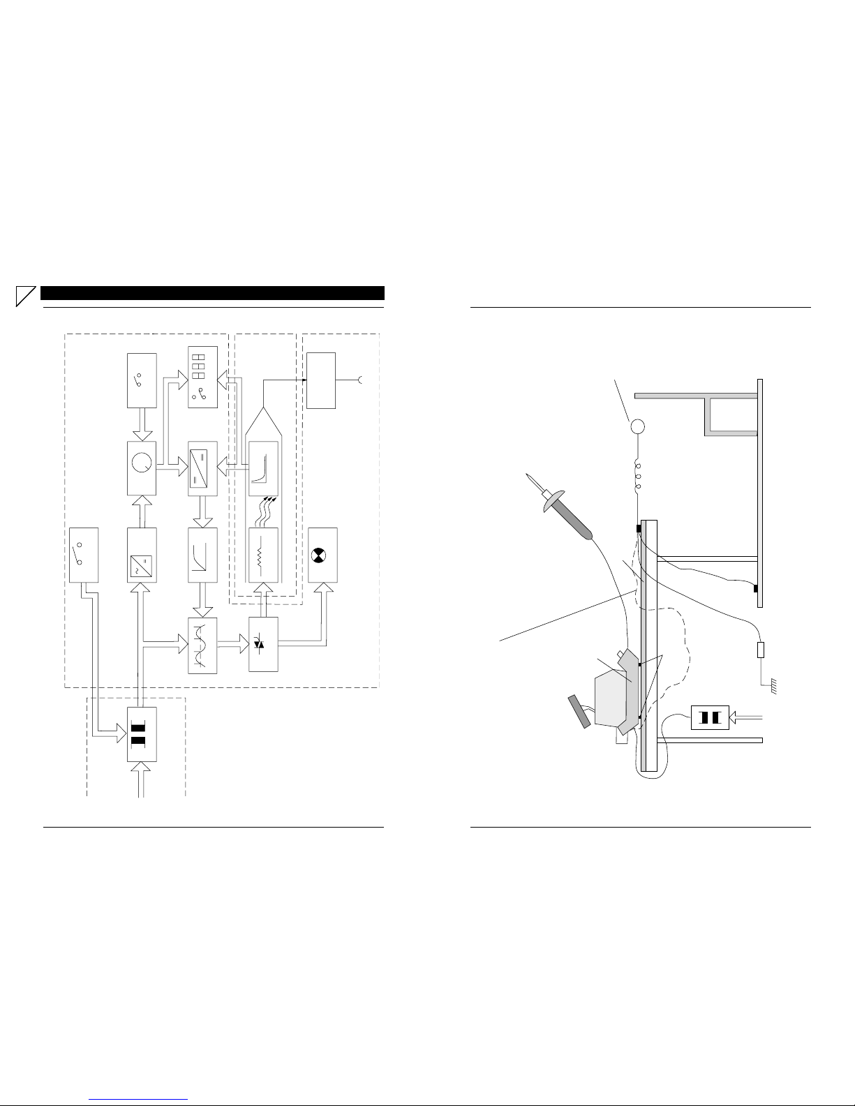
ELVO E911D/E911A/E912A 11
2.7.1 ESD - Working place overview
Clean-o-point
24 V AC approx. 100 kΩ
Soldering iron
Antistatic working floor (isoelectric)
Potential equalization
(workshop internal)
Rv
Mains supply
Mains transformer
Galvanic separation
Conducting rubber feet
approx. 10Ω- 2kΩ
Soldering station
ESD wristlet
Clean-o-point and soldering
station have the same potential
as the working base
Tip point
(same potential
as soldering station
and working base)
Hand lever (10 - 50 kΩ) thereby
no shock discharge of the user
(same potential is adjusted
automatically)
Antistatic working base
Additional potential equalization possible
22 ELVO E911D/E911A/E912A
DIAGRAMS
7
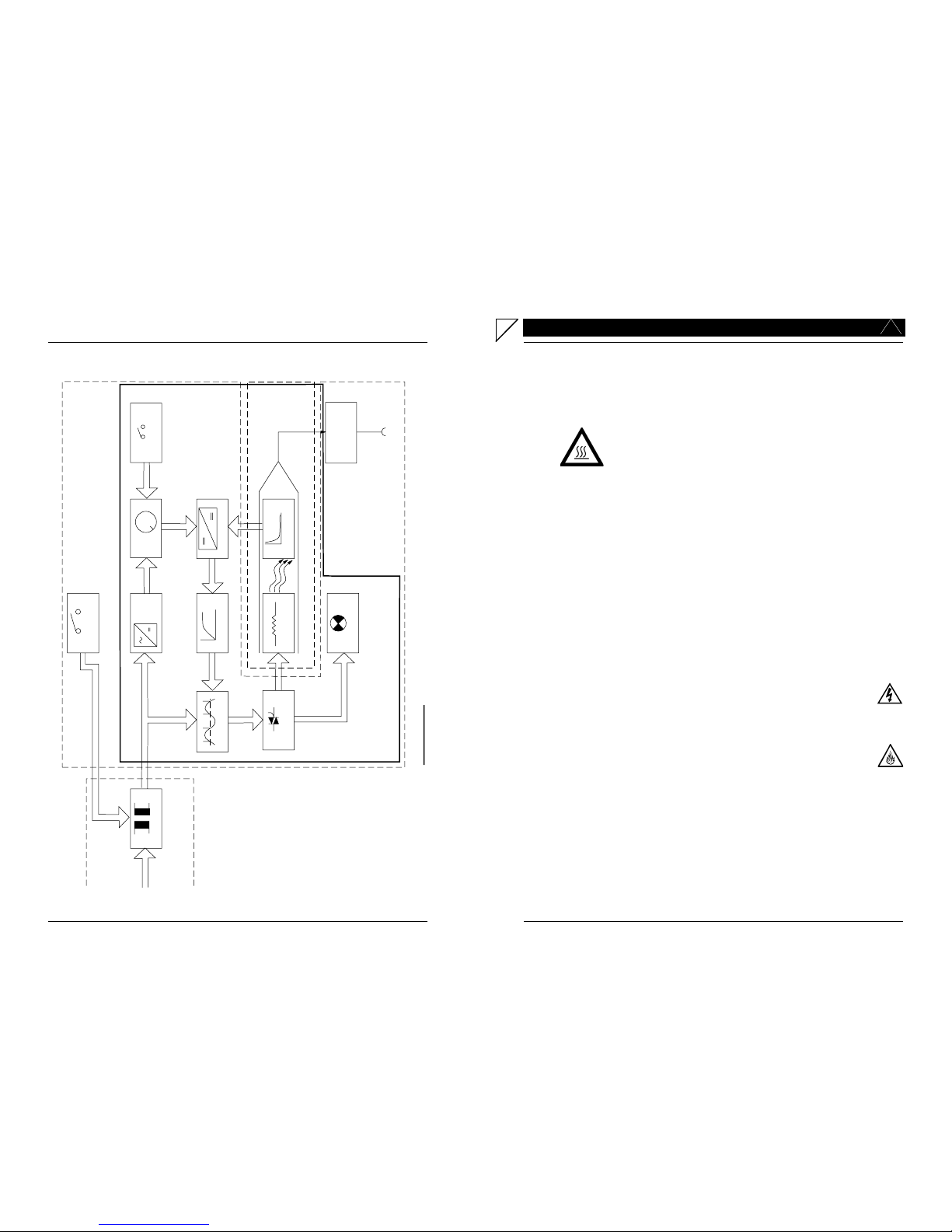
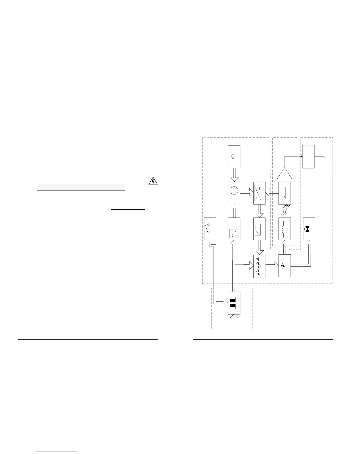
7.1 BLOCK DIAGRAM E911D
0
20
40 60
80
100 %
IST
Mains supply
Transformer
Separate mains transformer
Zero voltage detector
Switch
Heat display
Soldering iron
Heater element Te mp. - Sensor
Controller Comparator Nominal/Actual display
Standby
Nominal
Mains remote
control
Rectifier
Potential equalization
on housing and
working base
Connector
Tip point
Soldering station
12 ELVO E911D/E911A/E912A
INITIAL OPERATION
3
3.1 GENERAL FEATURES
•Soldering stations E911D / E911A / E912A
•clean-o-point®
•Soldering iron 55 Watt
•Iron holder
•Transformer
•Suspension device with hock screw
•Bag with spare sponges
•Copper cleaning brush
•Instruction manual
3.1.1 Feature Description
•Socket for potential equalization is installed on the rear side
(to avoid leakage of static charges)
•The soldering station is isolated from AC line by a transformer and
only 24 V AC isolated voltage is used to drive the heating element
•All housing parts are molded of high impact and high heat resistant
polycarbonate.
•The soldering iron is connected to the soldering station using a
temperature resistant and antistatic silicone rubber sheathed cable
with a five pin heavy duty plug with locking ring
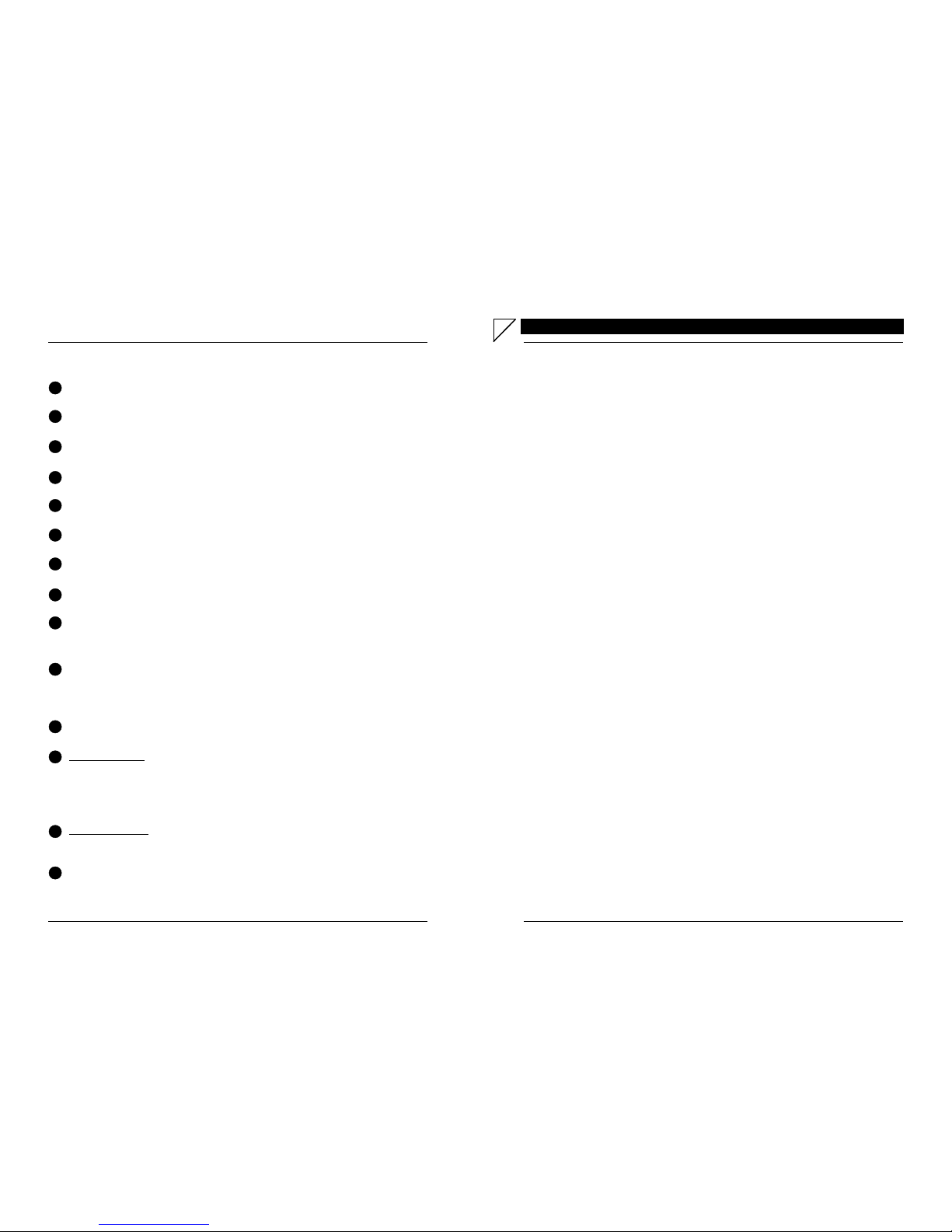
3.2 COMPONENTS ASSEMBLY
Assembly:
Press the station and the clean-o-point®firmly
together with both hands.
Iron holder:
Insert until it snaps in (1).
With the models E911A and E911D, the Stop +
Go switch can be blocked (if desired) by pushing
the corresponding slide lever backwards (2).
1
2
Transformer with suspension device
!
ELVO E911D/E911A/E912A 21
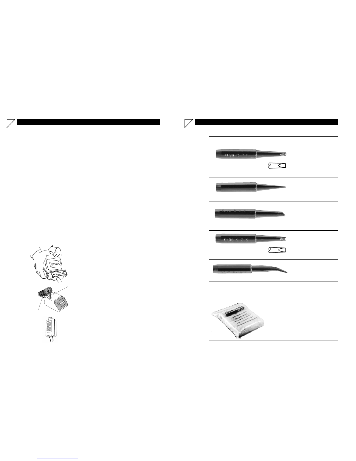
ACCESSORIES
6
Screw Driver Shape
Order number Dim.
4520 S 1.0 ≥1/32"
4520 S 1.5 1/16"
4520 S 2.0 5/64"
4520 S 2.5 3/32"
4520 S 3.0 1/8"
4520 S 3.6 ≤5/32"
4520 S 4.8 3/16"
Conical Shape
Order number Dim.
4520 C 0.3 1/64"
4520 C 0.6 .025"
4520 C 0.8 1/32"
Screw Driver Shape
Order number Dim.
4521 SL 1.2 1/32"
4521 SL 1.6 1/16"
4521 SL 2.0 5/64"
4521 SL 3.2 1/8"
Conical cranked
Order number Dim.
4521 CA 0.8 1/32"
Pointed Shape
Order number Dim.
4520 B 1.6 1/16"
4520 B 2.5 3/32"
4520 B 3.0 1/8"
4520 B 4.8 3/16"
Length = 46 mm (1.81")
Length = 46 mm (1.81")
Length = 46 mm (1.81")
Length = 52 mm (2.05")
Length = 52 mm (2.05")
6.2 SPARE SPONGES
6.1 TIPS
☞For SMT tips, ask for additional information
Spare sponges
8 pieces
Order number F3008
ELVO E911D/E911A/E912A 13
3.3 TEMPERATURE RANGE
ELVO soldering station delivers the full operating range of 140-450°C (280-
850°F) in the digital version and 150-400°C (300-840°F) in the analog ver-
sion without changing tip or heating element. The ceramics heating element
ensures the accurate temperature close to the surface of the tip. This results
in rapid heat up time of about 45 seconds and instant recovery.
3.3.1 Temperature Stability
Tip idling temperature stability is smaller than ±3°C (±10°F), corresponding
to MIL requirements. This is accomplished by embedding the thermocouple
sensing unit in the bevel of the heating element barrel. The measuring point is
nearest to the soldering tip. Only this method allows the closest possible moni-
toring of the temperature.
3.3.2 Working Temperature
A too low temperature will slow the solder flow; a high temperature will burn
the flux in the solder, which in turn will emit a heavy white smoke in a dry joint,
or damage the PCB. When the tip working temperature is set within the cor-
rect parameters suited to the particular solder being used a good joint is as-
sured. The most common solder alloys used in the electronic industry is 60%
tin, 40% lead (60/40). The tip working temperature of the solder is detailed
below and can vary from manufacturer to manufacturer:
Melting point: 188°C (370°F)
Normal operation: 270-320°C (518-608°F)
Production line operation: 320-380°C (608-716°F)
☞The temperature above 380°C (716°F) should not be used for normal
soldering functions but can be used for short periods of time when ex-
cessive heat is required.
Consider the recommendations of the manufacturers of
the diffrent components ! ▲
!
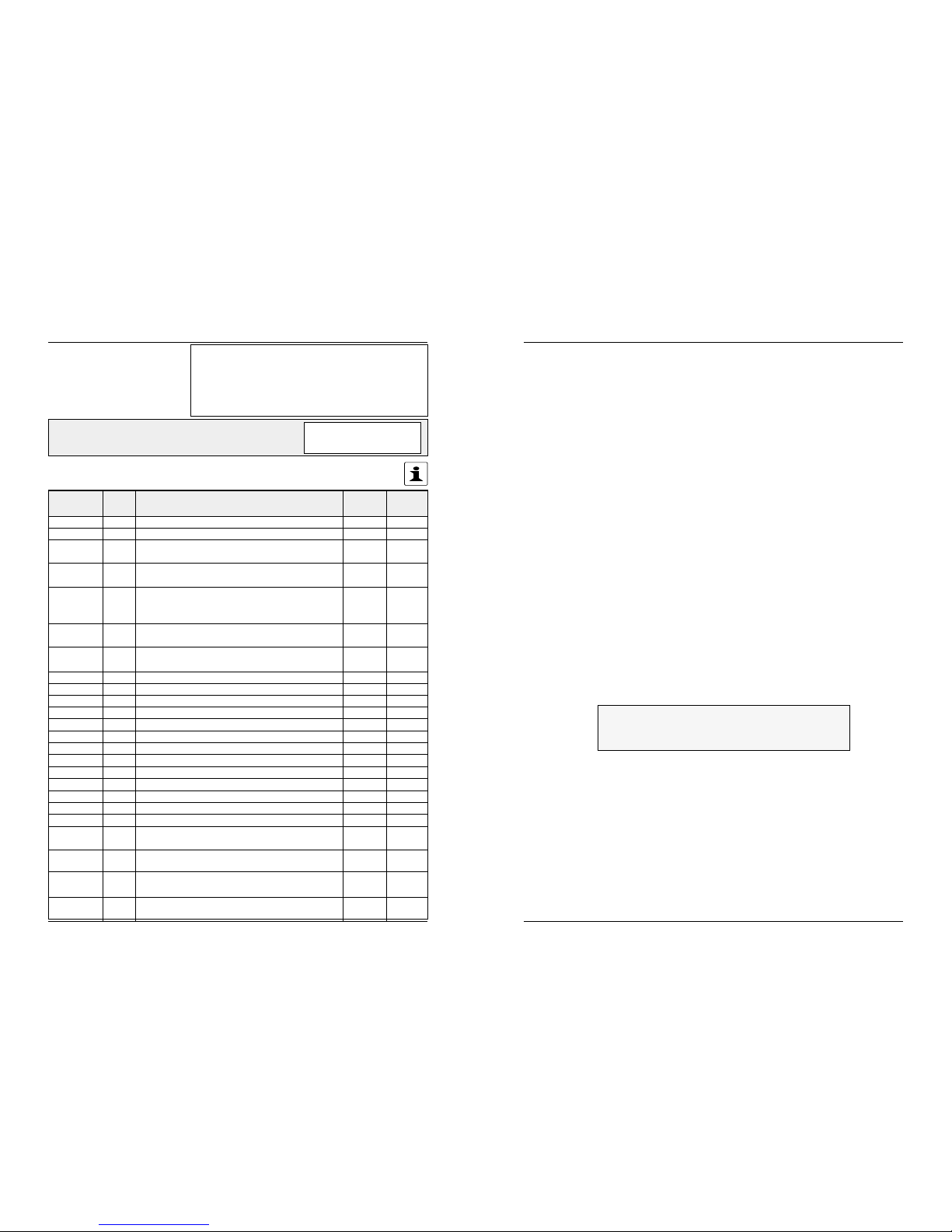
20 ELVO E911D/E911A/E912A
5.3 SPARE PARTS LIST Sender (Company name):
...................................................................................................
...................................................................................................
Send, ATTENTION to:
....................................................................
ORDER FORM Unit serial number:
(on the technical label)
For a quick response to your spare parts requirement kindly use the list below.
Just fill in the quantity of each part you require and send it to us - Thank you.
You will find the addresses at the end of this manual.
Part no.
ET4500 9 Soldering iron 55 W 1
ET4550 Heating element 1
ET4520 Soldering tips
Type S, B, C 1
ET4521 Soldering tips
Type SL, SS, CA 1
ET4522 Soldering tips SMD
Type SM8
SM14 1
Type SM16
SM23 1
Type SM0805
SM1206 1
Type SM5588 1
ET4523 SMD-Adapter 1
ET4524 Cleaning brush,Copper 1
ET3008 Spare sponges,(bag of 8 pieces) 1
ET3010 Front cover, black 1
ET3011 Tinbox, axe standards included 1
ET3012 8 Iron holder assembly 1
ET3015 Axe standards to tinbox ET3011 1
ET3016 Box ESD, black 1
ET3017 Box, green 1
ET3019 Holder 1
ET3020 Rocker switch 1
ET3021 Complete switch to "Stop & Go" 1
TR4200 Supply unit to E911D/A
230 VAC / 50 VA 1
TR4220 Supply unit to E912A
230 VAC / 100 VA 1
TR4111 Supply unit to E911D/A
115 VAC / 50 VA 1
TR4121 Supply unit to E912 A
115 VAC / 100 VA 1
Pos. Description Qty Order-
qty

14 ELVO E911D/E911A/E912A
3.4 OPERATING INSTRUCTIONS
E911D
1. Connect unit to mains.
Switch unit on. Green "Heater"
light will turn on.
2. The temperature will be read
on digital LED display.
3. Set nominal temperature by
holding "SET" switch
4. Rotate temperature control
knob until digital display reads
desired temperature (resolu-
tion ±1°)
5. Release "SET" switch. Tip
temperature is now rising
and being displayed.
6. During any work breaks,
move the switch on the
left to "Standby". When start-
ing work again, move it back
to "Heater" so that the tem-
perature last used will be re-
set automatically.
E911A / E912A
Connect unit to mains.
Switch unit on. Green "Heater"
light will turn on.
-
-
Rotate temperature control
knob to the desired tempera-
ture
-
During any work breaks,
move the switch on the
left to "Standby". When start-
ing work again, move it back
to "Heater" so that the tem-
perature last used will be re-
set automatically.
3
ELVO E911D/E911A/E912A 19
5.1 RETURN FOR REPAIRS
Should it prove necessary in the future to send the equipment back
for repair, please proceed as follows :
-enclose an exact description of the failure, including the
operational mode in which the failure or breakdown first occurred
-indicate clearly the person that should be contacted in your com-
pany and indicate the telephone and fax number
-for transportation, please use the original packing material (as far
it is still available). Should this no longer be available, please make
sure that the package protects the equipment adequately.
-assuming it is necessary and possible, send the entire equip-
ment back (soldering station and mains supply unit, accessories
etc.)
You can of course contact our service or sales departments by
telephone, telex or telefax. Our customer service will gladly
assist you. Addresses are listed in chapter 8
In order to assure best performance in function of your ELVO solder-
ing station, please consider following points. In case of a function
failure, please contact your next ELVO specialist.
5.2 CONDITIONS APPLYING TO SPARE PARTS
Only use original spare parts. Chapter 5.1 contains a list of standard
spare parts.
To use products from another source could harm
•safety,
•reliability and
•performance.
SERVICING
5
ELVO E911D/E911A/E912A 15
3.4.1 clean-o-point®- How it works
The clean-o-point®cleans tips with a remarkable self-cleaning motorized
wiping system that keeps tips clean, prolongs tip life, removes and collects
excess solder. Fast 1 second cleaning with damp sponges means no tem-
perature loss at the tip, no cold solder points to destroy PC boards.
☞see also chapter 4.4 - clean-o-point ®maintenance
Pb-Sn
▼
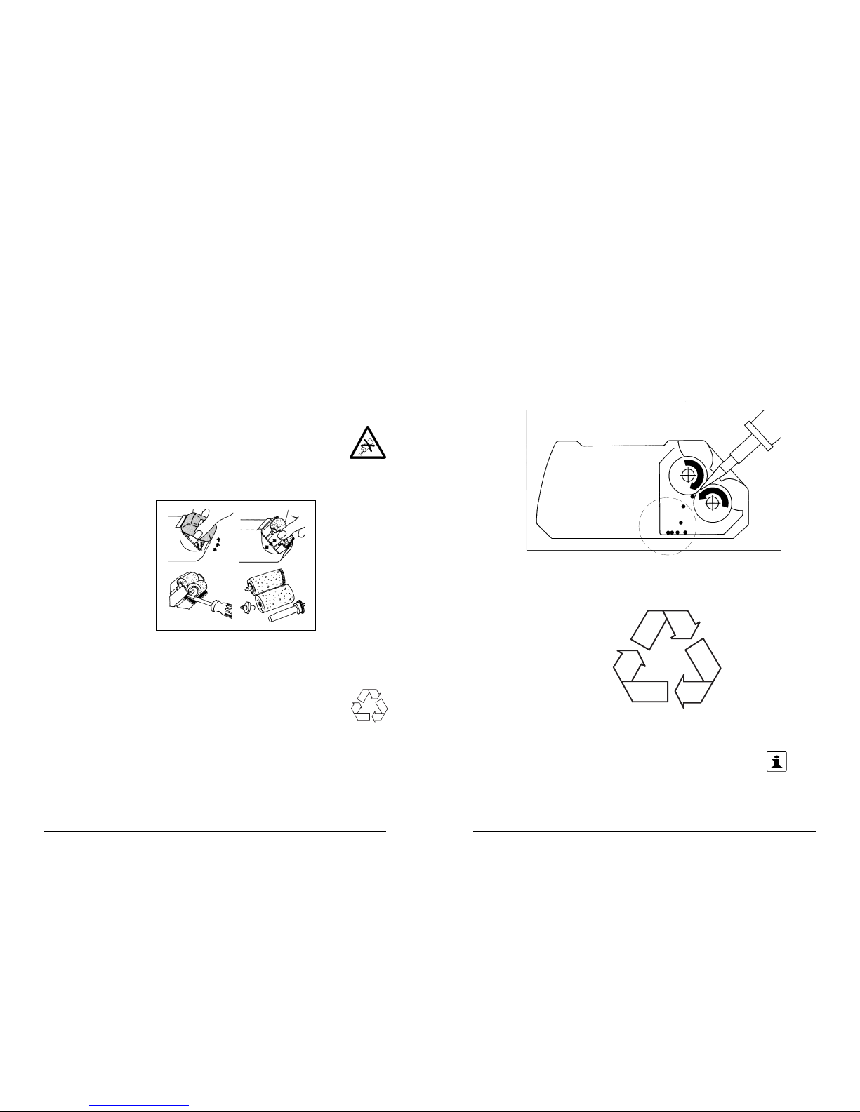
18 ELVO E911D/E911A/E912A
4.4 clean-o-point® MAINTENANCE
1. Before using for the first time, wash sponges carefully under
running water.
2. Rinse sponges under running water once only before begin-
ning the shift, and wring well. If the soldering tips are very
fine, wring more thoroughly. The sponges retain uniform hu-
midity for about 8 hours.
3. Do not wet the sponges by pouring water over them
in the unit. Overly wet sponges will cause excessive
cooling of soldering tips.
4. Replace sponges when incrusted with rosin (after about
1 month of all-day shifts).
☞Sponges are much cheaper than soldering tips !
5. Empty solder container before starting each 8-hour shift.
Wash and wring sponge rollers well.
☞Collect solder for recycling !
6. To clean the soldering tip, insert it with a steady movement
between the wet rotating sponge rollers. Cleaning takes less
than 1 second !
7. Soldering tips cleaned with clean-o-point®have a service
life
up to 10 times longer than tips cleaned with common flat
sponges.
▲
!
Pb-Sn
16 ELVO E911D/E911A/E912A
MAINTENANCE
4
▲
!
▲
!
4.1 GENERAL CLEANING
The outer case of iron or station may be cleaned with a damp cloth
using little amounts of liquid detergents.
☞Never submerge the unit in liquid or allow any to enter
the case of the station.
Never use any solvent to clean the case.
(Decomposition of the writing and / or deformation on
the housing)
4.2 CARE OF TIPS
The tips supplied are iron plated copper and if used properly will
give a long life.
1. Always keep tips tinned before switching off or storing for a
long period of time; Wipe tip using clean-o-point.
Caution with long hair!
2. Don't keep iron set at high temperature for long periods
as this will break down the surface of the tip.
3. Never clean tips with abrasive materials or files.
4. If any oxide film is formed, this can be cleaned with the clean-
ing brush, isoproyl alcohol or equivalent, and then imme-
diately reheat and retain the tip to prevent oxidation of
wettable surface.
5. Remove the tip and clean every twenty-four hours or at least
once a week. Remove any loose build up in the barrel.
6. Do not use fluxes containing chloride or acid.
Use only rosin or activated resin fluxes.
7. Do not use any compound or antiseize materials on
the wettable surface.
▲
!
ELVO E911D/E911A/E912A 17
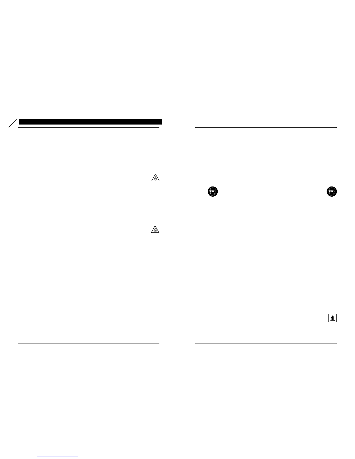
4.3 TIP REPLACEMENT AND DRESSING
Tip can be replaced simply by unscrewing the knurled nut barrel
assembly. The station must be switched off and allowed to cool during
this operation, as damage may result if the system is left on
without the tip inserted. After removing tip, blow out any oxide
dust that may have formed in the tip retaining area of the barrel. Be
careful to avoid getting dust in your eyes. Replace the tip and screw
back the retaining knurled nut barrel assembly using only firm hand
pressure to tighten. Pliers should only be used to tighten the nut to
avoid burning your fingers.
Wear protection spectacles!
☞Care should be taken not to overtighten as this
would damage the heating element.
4.3.1 Commissioning of New Tips
☞The following procedures should be followed when a new
tip has been installed at any time. It will give the tip much
longer life.
1. Set temperature to the minimum, then switch power to "ON".
2. After approx. 1 minute set temperature to 200°C (392°F).
(Beginning of scale)
3. Tinn the surface with resin core solder containing
collophonium after having reached 200°C (392°F).
4. Set to desired temperature and let it heat for approx. 5
minutes.
5. Ready for use after reaching the present desired tempera-
ture.
☞Important: Remove tip and clean daily if a new tip is
installed and removed any loose build up
in the barrel !
(For Tip Selector Charts, see chapter 6 !)
▲
!
▲
!
This manual suits for next models
2
Table of contents


