manuals.online logo
Brands
  1. Home
  2. •
  3. Brands
  4. •
  5. Elvox
  6. •
  7. Intercom System
  8. •
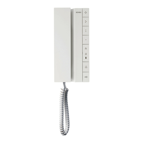
  9. Elvox 7400 User manual

Elvox 7400 User manual

Other Elvox Intercom System manuals

Elvox 637G/S1 User manual

Elvox

Elvox 637G/S1 User manual

Elvox PETRARCA 6150 User manual

Elvox

Elvox PETRARCA 6150 User manual

Elvox 1200 Series Assembly instructions

Elvox

Elvox 1200 Series Assembly instructions

Elvox Giotto 6344 User manual

Elvox

Elvox Giotto 6344 User manual

Elvox 735B User manual

Elvox

Elvox 735B User manual

Elvox 6680/C17 Assembly instructions

Elvox

Elvox 6680/C17 Assembly instructions

Elvox Vimar K40517G.01 User guide

Elvox

Elvox Vimar K40517G.01 User guide

Elvox 5721 User guide

Elvox

Elvox 5721 User guide

Elvox 68TU/93V User manual

Elvox

Elvox 68TU/93V User manual

Elvox 6202/A User manual

Elvox

Elvox 6202/A User manual

Elvox 682G/R Assembly instructions

Elvox

Elvox 682G/R Assembly instructions

Elvox Vimar 8000 Series User manual

Elvox

Elvox Vimar 8000 Series User manual

Elvox 8879 User manual

Elvox

Elvox 8879 User manual

Elvox 68IG/R Assembly instructions

Elvox

Elvox 68IG/R Assembly instructions

Elvox Giotto 6329 Assembly instructions

Elvox

Elvox Giotto 6329 Assembly instructions

Elvox 837/OCT User manual

Elvox

Elvox 837/OCT User manual

Elvox 69PH Assembly instructions

Elvox

Elvox 69PH Assembly instructions

Elvox 68TU/K93 User manual

Elvox

Elvox 68TU/K93 User manual

Elvox Vimar K40912 User manual

Elvox

Elvox Vimar K40912 User manual

Elvox 6614 User manual

Elvox

Elvox 6614 User manual

Elvox Petrarca 62KG User manual

Elvox

Elvox Petrarca 62KG User manual

Elvox 6600 Series Assembly instructions

Elvox

Elvox 6600 Series Assembly instructions

Elvox 6621 User manual

Elvox

Elvox 6621 User manual

Elvox 85CE/240 User manual

Elvox

Elvox 85CE/240 User manual

Popular Intercom System manuals by other brands

Videx VRDK1 (25H) Technical manual

Videx

Videx VRDK1 (25H) Technical manual

Auta COMPACT VISUALTECH manual

Auta

Auta COMPACT VISUALTECH manual

Aiphone LC-10S instructions

Aiphone

Aiphone LC-10S instructions

Aiphone PD-1 instructions

Aiphone

Aiphone PD-1 instructions

Aiphone JF-DVF-HID-I instructions

Aiphone

Aiphone JF-DVF-HID-I instructions

Comelit 4893M Technical manual

Comelit

Comelit 4893M Technical manual

MGL Avionics V16 manual

MGL Avionics

MGL Avionics V16 manual

SSS Siedle BVI 750-0 Installation & programming

SSS Siedle

SSS Siedle BVI 750-0 Installation & programming

urmet domus AIKO 1716/1 quick start guide

urmet domus

urmet domus AIKO 1716/1 quick start guide

urmet domus IPerVoice 1039 Installation

urmet domus

urmet domus IPerVoice 1039 Installation

Alpha Communications STR QwikBus TT33-2 Installation, programming, and  user's manual

Alpha Communications

Alpha Communications STR QwikBus TT33-2 Installation, programming, and user's manual

Monacor ICM-20H instruction manual

Monacor

Monacor ICM-20H instruction manual

Logenex A202CR Installation & programming

Logenex

Logenex A202CR Installation & programming

Quantum QR5 Installation and programming manual

Quantum

Quantum QR5 Installation and programming manual

EVGA XR1 quick guide

EVGA

EVGA XR1 quick guide

CyberData 011211 series Installation quick reference

CyberData

CyberData 011211 series Installation quick reference

Vidos duo M1021 user manual

Vidos

Vidos duo M1021 user manual

Savant DOR-SMS-00 Deployment guide

Savant

Savant DOR-SMS-00 Deployment guide

manuals.online logo
manuals.online logoBrands
  • About & Mission
  • Contact us
  • Privacy Policy
  • Terms and Conditions

Copyright 2025 Manuals.Online. All Rights Reserved.

CITOFONO - INTERPHONE - POSTE
HAUSTELEFON - INTERFONO - TELEFONE
MANUALE PER IL COLLEGAMENTO
WIRING INSTRUCTIONS
INSTRUCTIONS POUR LA CONNEXION
ANWEISUNGEN FÜR DEN ANSCHLUSS
MANUAL PARA EL CONEXIONADO
INSTRUÇÕES PARA A LIGAÇÃO
ART. 7400
Cod. S6I.740.000 RL. 00 4/2007
Il prodotto è conforme alla direttiva europea 89/336/CEE e successive.
Product is according to EC Directive 89/336/EEC and following norms.
2
A- Entrance panel series GALILEO with
Art. 8B81, 8B82, 8B83
B- Additional push-button for lock
C- 12V A.C. electric lock
D- Speech unit Art. 930
E- Microphone
L1- Panel lamp
(3x24V 3W max)
10x24V 3W with Art. M832
16x24V 3W with Art. 832/030
A- Targa serie GALILEO con
Art. 8B81, 8B82, 8B83
B- Pulsante supplementare serratura
C- Serratura elettrica 12Vc.a.
D- Posto esterno Art. 930
E- Microfono
L1- Lampada luce targa
(3x24V 3W max)
10x24V 3W con Art. M832
16x24V 3W con Art. 832/030
A - Plaque de rue pour portier série GALILEO avec
Art. 8B81, 8B82, 8B83
B - Poussoir supplémentaire gâche
C - Gâche électrique 12V c.a.
D - Micro et haut-parleur Art. 930
E- Microphone
L1- Lampe d’éclairage plaque
(3x24V 3W max)
10x24V 3W avec Art. M832
16x24V 3W avec Art. 832/030
A - Türsprechstelle serie GALILEO mit
Art. 8B81, 8B82, 8B83
B - zusätzliche Türöffnertaste
C - Elektrischer Türöffner 12V∼
D - Sprechstelle Art. 930
E- Mikrofon
L1- Klingeltableaubeleuchtung
(3x24V 3W max)
10x24V 3W mit Art. M832
16x24V 3W mit Art. 832/030
A - Placa para portero serie GALILEO con
Art. 8B81, 8B82, 8B83
B - Pulsador suplementario cerradura
C- Cerradura eléctrica 12V c.a.
D - Aparato externo Art. 930
E- Micrófono
L1- Lámpara luz escalera
(3x24V 3W max)
10x24V 3W con Art. M832
16x24V 3W con Art. 832/030
A - Botoneira serie GALILEO com
Art. 8B81, 8B82, 8B83
B - Botão suplementar de trinco
C - Trinco eléctrico 12V∼
D - Posto externo Art. 930
E- Microfone
L1 - Lâmpada da luz da botoneira
(3x24V 3W max)
10x24V 3W com Art. M832
16x24V 3W com Art. 832/030
Sezione conduttori - Conductor section
Sections des conducteurs-Leiterquerchnitt
Secciones conductores-Secção condutores
Conduttori-Conductors Ø fino a 50m-Ø up to 50m Ø fino a 100m-Ø up to 100m Ø fino a 200m-Ø up to 200m
Conductors-Leitungslänge Ø jusqu’à 50m-Ø bis 50m Ø jusqu’à 100m.-Ø bis 100m Ø jusqu’à 200m.-Ø bis 200m
Conductores-Condutores Øhasta 50m - até 50m Ø hasta 100m - até 100m Ø hasta 200m - Ø até 200m
- + serratura +T
- + lock +T
- + gâche +T
- + Türöffner +T 1 mm² 1,5 mm² 2,5 mm²
- + cerradura +T
- + trinco +T
Altri-Others-Autres
Andere-Otros-Outros 0,75 mm² 1 mm² 1,5 mm²
Video Cavo coassiale 75 Ohm (tipo RG59)
Video 75 Ohm coaxial cable (type RG59)
Vidéo Câble coax. 75 Ohm (type RG59)
Video 75 Ohm Koaxialkabel RG59
Vídeo Cable coaxial de 75 Ohm (tipo RG59)
Vídeo Cabo coaxial de 75 Ohm (tipo RG59)
ELVOX
GALILEO
A
B
L1
321CH
D
C
S+U C2
E
PRI
27C2 31C18615AS0
8
9
3
1
2
4
5
7
6
5
8
3
4
S5 S1
PRI
+I-A+U B C D
6
11
12
3
IMPIANTO CITOFONONICO MONO-PLURIFAMILIARE A VIVA VOCE CON CITOFONI ART. 7400 E 7401
HANDS-FREE MONO-PLURIRESIDENTIAL AUDIO DOOR ENTRY SYSTEM WITH
INTERPHONES ARTS. 7400 AND 7401
INSTALLATION DE PORTIER AUDIO À VIVE VOIE POUR UNE-DEUX VILLAS
AVEC POSTES D'APPARTEMENT ART. 7400 ET 7401
FREI-HANDSBETRIEB EIN-ZWEIFAMILEINHÄUSER
AUDIOTÜRSPRECHANLAGE MIT HAUSTELEFONEN ART. 7400 UND 7401
INSTALACIÓN DE PORTERO AUDIO MONO-PURIFAMILIAR A VIVA VOZ CON INTERFONOS ART. 7400 Y 7401
INSTALAÇÃO DE PORTEIRO AUDIO MONO-PLURIFAMILIAR DE ALTA VOZ COM
INTERFONES ART. 7400 E 7401
ALIMENTATORE - POWER SUPPLY
ALIMENTATION - NETZGERÄT
ALIMENTADOR ART. 6450
RETE - NETWORK
RÉSEAU - NETZ
RED - REDE
MONTANTE CITOFONI
INTERPHONES CABLE RISER
HAUSTELEFONSTEIGLEITUNG
COLONNE MONTANTE POSTES
MONTANTE INTERFONES
COLUNA MONTANTE
PARA OS TELEFONES
N° c3787
CITOFONO
PHONE
POSTE
HAUSTELEFON
INTERFONO
TELEFONE
Art. 7400
N.B. in caso di ronzio sulla fonica spostare il filo
collegato sul morsetto 15 al morsetto "AS".
N.B. In case of buzzing on the phonic line
displace wire connected on terminal 15 to ter-
minal "AS".
N.B. En cas de bourdonnement sur la ligne de
phonique déplacer le fil de la borne 15 à la
borne "AS".
HINWEIS: Falls Brumgeräusch auf der
Audiolinie den an der 15 Klemme angeschlos-
senen Draht auf "AS" Klemme untauschen.
N.B. En caso de ruido en la linea de fónica
desplazar el hilo del borne 15 al borne "AS".
N.B. No caso de ruido na linha de fónica mudar
o fio do borne 15 ao borne "AS".
RETE - NETWORK
RÉSEAU - NETZ
RED - REDE
ALIMENTATORE
POWER SUPPLY
ALIMENTATION
NETZGERÄT
ALIMENTADOR
ART. 6582
ALTOPARLANTE
LOUDSPEAKER
LAUTSPRECHER
HAUT-PARLEUR
ALTAVOZ
ALTIFALANTE
TASTI DI CHIAMATA
CALL PUSH-BUTTON
POUSSOIRS D’APPEL
RUFTASTEN
PULSADORES DE
LLAMADA
BOTÕES DE
CHAMADA
MICROFONO
MICROPHONE
MIKROFON
MICRÓFONO
MICROFONE
4
A- Entrance panel series GALILEO with
Art. 8B81, 8B82, 8B83
B- Additional push-button for lock
C- 12V A.C. electric lock
D- Camera with speech unit Art. 558, 559
L1- Panel lamp
(3x24V 3W max)
10x24V 3W with Art. M832
16x24V 3W with Art. 832/030
A- Targa serie GALILEO con
Art. 8B81, 8B82, 8B83
B- Pulsante supplementare serratura
C- Serratura elettrica 12Vc.a.
D- Telecamera con posto esterno Art. 558, 559
L1- Lampada luce targa
(3x24V 3W max)
10x24V 3W con Art. M832
16x24V 3W con Art. 832/030
A - Plaque de rue pour portier série GALILEO avec
Art. 8B81, 8B82, 8B83
B - Poussoir supplémentaire gâche
C - Gâche électrique 12V c.a.
D - Caméra avec micro et haut-parleur Art. 558, 559
L1- Lampe d’éclairage plaque
(3x24V 3W max)
10x24V 3W avec Art. M832
16x24V 3W avec Art. 832/030
A - Türsprechstelle serie GALILEO mit
Art. 8B81, 8B82, 8B83
B - zusätzliche Türöffnertaste
C - Elektrischer Türöffner 12V∼
D - Kamera mit Sprechstelle Art. 558, 559
L1- Klingeltableaubeleuchtung
(3x24V 3W max)
10x24V 3W mit Art. M832
16x24V 3W mit Art. 832/030
A - Placa para portero serie GALILEO con
Art. 8B81, 8B82, 8B83
B - Pulsador suplementario cerradura
C- Cerradura eléctrica 12V c.a.
D - Cámara con aparato externo Art. 558, 559
L1- Lámpara luz escalera
(3x24V 3W max)
10x24V 3W con Art. M832
16x24V 3W con Art. 832/030
A - Botoneira serie GALILEO com
Art. 8B81, 8B82, 8B83
B - Botão suplementar de trinco
C - Trinco eléctrico 12V∼
D - Telecâmara com posto externo Art. 558, 559
L1 - Lâmpada da luz da botoneira
(3x24V 3W max)
10x24V 3W com Art. M832
16x24V 3W com Art. 832/030
Sezione conduttori - Conductor section
Sections des conducteurs-Leiterquerchnitt
Secciones conductores-Secção condutores
Conduttori-Conductors Ø fino a 50m-Ø up to 50m Ø fino a 100m-Ø up to 100m Ø fino a 200m-Ø up to 200m
Conductors-Leitungslänge Ø jusqu’à 50m-Ø bis 50m Ø jusqu’à 100m.-Ø bis 100m Ø jusqu’à 200m.-Ø bis 200m
Conductores-Condutores Øhasta 50m - até 50m Ø hasta 100m - até 100m Ø hasta 200m - Ø até 200m
- + serratura +T
- + lock +T
- + gâche +T
- + Türöffner +T 1 mm² 1,5 mm² 2,5 mm²
- + cerradura +T
- + trinco +T
Altri-Others-Autres
Andere-Otros-Outros 0,75 mm² 1 mm² 1,5 mm²
Video Cavo coassiale 75 Ohm (tipo RG59)
Video 75 Ohm coaxial cable (type RG59)
Vidéo Câble coax. 75 Ohm (type RG59)
Video 75 Ohm Koaxialkabel RG59
Vídeo Cable coaxial de 75 Ohm (tipo RG59)
Vídeo Cabo coaxial de 75 Ohm (tipo RG59)
5
SCHEMA COLLEGAMENTO VIDEOCITOFONO CON CITOFONO ART. 7400, MONITOR 7000 E ALIMENTA-
TORE ART. 6681.
WIRING DIAGRAM FOR VIDEO INTERCOM SISTEM WITH INTERPHONE ART. 7400, MONITOR 7000 AND
POWER SUPPLY ART. 6681.
SCHÉMA DE RACCORDEMENT POUR PORTIER VIDÉO AVEC INTERPHONE ART. 7400, MONITEUR 7000
ET ALIMENTATION ART. 6681.
SCHALTPLAN FUER VIDEO-TÜRSPRECHANLAGE MIT HAUSTELEFON ART. 7400, MONITOR ART. 7000
UND NETZGERAET ART. 6681.
ESQUEMA DE CONEXIONADO PARA VIDEO PORTERO CON INTERFONO ART. 7400, MONITOR ART. 7000
Y ALIMENTADOR ART. 6681.
ESQUEMA DE LIGAÇÃO PARA VIDEO PORTEIRO COM INTERFONE ART. 7400, MONITOR ART. 7000 E
ALIMENTADOR ART. 6681.
ALIMENTATORE - POWER SUPPLY
ALIMENTATION - NETZGERÄT
ALIMENTADOR ART. 6681
RETE - NETWORK
RÉSEAU - NETZ
RED - REDE
MONTANTE MONITOR
MONITOR CABLE RISER
MONITORE STEIGLEITUNG
COLONNE MONTANTE MONITEURS
MONTANTE MONITOR
COLUNA MONTANTE
PARA OS MONITORES
MONITOR
MONITEUR
Art. 7000 + 7145
MICROFONO
MICROPHONE
MIKROFON
MICRÓFONO
MICROFONE
N° vc3623
CITOFONO
PHONE
POSTE
HAUSTELEFON
INTERFONO
TELEFONE
Art. 7400
N.B.
In caso di ronzio sulla fonica spostare il commutatore "A-B"
situato sotto il coperchio in posizione "A".
If a humming sounds is detected on the phonic line, set
slide switch "A-B" under the cover to position "A".
En cas de bourdonnement sur la ligne phonique déplacer le
commutateur "A-B", situé sous le couvercle, sur la position "A".
Ist bei der Audioverbindung ein Brummton zu hören, muß
der Schiegeschalter "A-B" unter dem Gehäusedeckel in
Position "A" gebracht werden.
En caso de zumbido en la fonica desplazar el conmutador
"A-B" que se encuentra debajo de la tapa en la posición "A".
No caso de ruído na linha audio mudar o comutador "A-B"
situado na tampa para a posição "A".
MICROFONO
MICROPHONE
MIKROFON
MICRÓFONO
MICROFONE
TELECAMERA CON
ALTOPARLANTE
CAMERA WITH
LOUDSPEAKER
KAMERA MIT
LAUTSPRECHER
CAMÉRA AVEC
HAUT-PARLEUR
CÁMARA CON
ALTAVOZ
TELECÂMARA COM
ALTIFALANTE
TASTI DI CHIAMATA
CALL PUSH-BUTTON
POUSSOIRS D’APPEL
RUFTASTEN
PULSADORES DE
LLAMADA
BOTÕES DE
CHAMADA
6
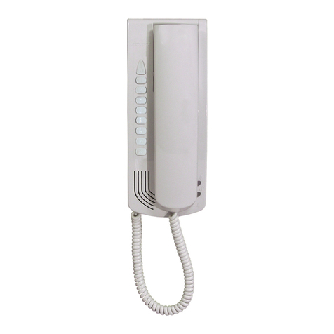
Citofono munito di altoparlante per chia-
mata elettronica, pulsante serratura, pul-
sante autoaccensione, pulsante supple-
mentare, pulsante di abilitazione fonica,
regolazione intensità di chiamata, esclu-
sione chiamata con LED di seg-
nalazione, regolazioni volume interno e
esterno. Il citofono è da utilizzare esclu-
sivamente su impianti viva voce
bicanale con alimentatore Art. 6450 e
Art. 6681.
Per attivare la conversazione dopo la
chiamata da targa, premere il pulsante
e tenerlo premuto durante tutta la
conversazione.
Regolazioni esterne
A) PULSANTE " "
Comando serratura elettrica con
LED di segnalazione di chiamata
acustica esclusa.
B) PULSANTE " "
Pulsante per servizi ausiliari (luce
scale, ecc.). Se collegato al sis-
tema "VIDEOMOVING" della
targa esterna video, tenendolo
premuto, questo pulsante serve
per regolare l'inclinazione dell'an-
golo di ripresa verticale della tele-
camera in modo da riprendere
soggetti ravvicinati di diversa
statura.
C) PULSANTE " "
Autoaccensionedell'impianto dal-
l'interno ed inserimento tele-
camere supplementari (dove pre-
visto).
D) PULSANTE " "
Comando attivazione collega-
mento audio con la targa esterna
(tenere premuto per conversare).
Regolazioni interne
P1) VOLUME INTERNO
P2) VOLUME ESTERNO – (posizion-
ato all’interno del citofono).
P3) REGOLAZIONE INTENSITÁ
CHIAMATA ED ESCLUSIONE
CHIAMATA
CITOFONO VIVA VOCE BICANALE DA
ESTERNO PARETE.
DUAL-CHANNEL OPEN VOICE INTER-
PHONE FOR SURFACE WALL-MOUNT-
ING.
INTERPHONE VIVE VOIX BICANAL
POUR MONTAGE EN SAILLIE
HAUSTELEFON MIT ZWEIKANAL
FREISPRECHEINRICHTUNG FUER AP-
MONTAGE.
INTERFONO VIVA VOX BICANAL PARA
MONTAJE DE EXTERNO PARED
INTERFONE ALTA VOZ BICANAL PARA
MONTAGEM SALIENTE.
Interphone equipped with: loud-
speaker for electronic call, doorlock
release push-button, additional
push-button, audio enabling push-
button, call volume adjustment, call
exclusion with signalling LED, inter-
nal and external volume adjustment.
Interphone is to be used only on
dual-channel open voice installa-
tions with power supplier Art. 6450
and Art. 6681.
To make the contact after the call
from the door entry panel, press
push-button and keep it
pressed during the all conversation.
External adjustments
A) BUTTON " "
Electric door lock control with
excluded acoustic call sig-
nalling LED.
B) BUTTON " "
Auxiliary service button (stair
light etc.). If connected to the
VIDEO MOVING system on the
external camera entrance
panel, simply hold this button
pressed down to tilt the video
camera lens up and down in
order to perfectly frame callers
of varying heights.
C) BUTTON " "
Internal automatic system start
and activation of the supple-
mentary video cameras (if fit-
ted)
D) BUTTON " "
Controls audio connection with
the external entrance panel
(press and hold to converse).
Internal adjustments
P1) "LISTEN" VOLUME
P2) "TALK" VOLUME – (place on
interfone inside)
P3)
CALL VOLUME ADJUSTMENT
AND CALL EXCLUSION.
GBI
ACBD
P1 P3 P2
7
Poste equippé avec haut-parleur
pour les appels électroniques,
bouton-poussoir gâche, bouton-
poussoir auto-enclenchement,
bouton-poussoir supplémentaire,
bouton-poussoir pour habilitation
phonique, réglage du volume
d’appel, exclusion de l’appel avec
LED de signalisation, réglages
volume interne et externe.
Le poste doit être utilisé seule-
ment dans les installation à vive
voix bicanal avec alimentation
Art. 6450 et Art. 6681.
Pour entrer en conversation,
après l’appel de la plaque de rue,
presser le bouton-poussoior
et le maintenir pressé pendant
toute la conversation.
Réglages externes
A) BOUTON-POUSSOIR
""
Contrôle gâche avec LED de
signalisation d’appel acous-
tique exclue.
B) BOUTON-POUSSOIR. " "
1° bouton-poussoir pour
services auxiliaires (éclairage
de l'escalier, etc...). S’il est
relié au système "VIDEO-
MOVING" de la platine de rue
avec caméra et si on le main-
tient pressé, ce bouton-pous-
soir sert à régler l’inclinaison
de l’angle de reprise verticale
de la caméra de manière à
filmer les sujets rapprochés
de différente taille.
C) BOUTON-POUSSOIR.
""
Auto-allumage de l’installa-
tion depuis l’intérieur et
enclenchement des caméras
supplémentaires (si
prévues).
D)
BOUTON-POUSSOIR " "
Commande activation liaison
audio avec la plaque
extérieure (garder appuyé
pour converser) .
Réglages internes
P1) VOLUME INTERNE.
P2) VOLUME EXTERNE –
(placé à l’interieur du poste).
P3) RÉGLAGE DU VOLUME
D’APPEL ET EXCLUSION
DE L’APPEL.
Interfono equipado con altavoz
para las llamadas electrónicas,
pulsador cerradura, pulsador
auto-encendido, pulsador suple-
mentario, pulsador para habil-
itación de la fónica, regulación
del volumen de la llamada,
exclusión de la llamada con LED
de señalación, regulaciones volu-
men interno y externo.
Utilizar el interfono exclusiva-
mente en instalaciones de viva
vox bicanal con alimentador Art.
6450 y Art. 6681.
Para comenzar la conversation,
después de la llamada de la
placa, presionar el pulsador
y mantenerlo presionado durante
toda la conversación.
Ajustes externos
A) PULSADOR " "
Mando cerradura eléctrica
con LED de señalación de
llamada acústica excluido.
B) PULSADOR " "
Para servicios auxiliares (luz
escalera, etc.). Si este pul-
sador está conectado con el
sistema VIDEOMOVING de
la placa externa video, se
puede regular la inclinación
del ángulo de captación verti-
cal para captar sujetos cer-
canos de diferentes alturas.
C) PULSADOR " "
Autoencendido de la insta-
lación desde el interior e
inserción de las instalación
cámaras suplementarias (si
conectadas).
D) PULSADOR " "
Mando activación conexión
audio con placa externa
(mantener presionado para
poder conversar).
Regulación interna
P1) VOLUMEN INTERNO
P2)VOLUMEN EXTERNO –
(situado en interior del inter-
fono)
P3) REGULACIÓN DEL VOLU-
MEN DE LLAMADA Y
EXCLUSIÓN LLAMADA
Telefone equipado com : alti-
falante para chamadas elec-
trónicas, botão do trinco, botão
autoacendimento, botão suple-
mentar, botão para possibilitar
a fónica, regulação do volume
de chamada, exclusão da
chamada com LED de sinaliza-
ção, regulação do volume inter-
no e externo.
O telefone deve ser utilizado
exclusivamente nas instalações
de alta voz bicanal com alimen-
tador Art. 6450 e Art. 6681.
Para activar a conversação,
após a chamada da botoneira,
premir o botão e o manter
premido durante toda a conver-
sação.
Regulações externas
A) BOTÃO
Mando do trinco eléctrico
com LED de sinalização de
chamada acústica excluído.
B) BOTÃO
È utilizado para os serviços
auxiliares (lux de escadas,
etc.). Se ligado ao sistema
"VIDEOMOVING" da telecâ-
mara botoneira exterior,
mantendo-o premido, per-
mite regular o ângulo de
focagem vertical a focar
pessoas de diferentes
alturas.
C) BOTÃO
Para autoacendimento da
instalação a partir do interior
e inserção das telecâmaras
suplementares (quando pre-
vistas).
D) BOTÃO “ ”
Comando para activar a lig-
ação audio com a botoneira
externa (manter premido
para conversar) .
Regulações internas
P1) VOLUME INTERNO
P2) VOLUME EXTERNO –
(colocado no interior do
telefone)
P3) REGULAÇÃO DO VOL-
UME DA CHAMADA E
EXCLUSÃO DA CHAMA-
DA.
Haustelefon mit Lautsprecher für den
elektronischen Ruf, Türöffnertaste,
Selbsaktivierungstaste, Audiofreigabetaste,
Rufauschliessung mit Anzeigetaste, Intern-
und Externlautstärkeregelungen ausgettatet.
Der Haustelefon muß ausschließlich
in Installationen mit Doppelkanal
Freisprecheinrichtung und mit
Netzgerät Art. 6450 und Art. 6681
verwendet werden.
Um das Gespräch nach dem
Klingeltableauruf zu aktivieren,
drücken Sie die Taste und
gedrückt behalten sie Sie während
des ganzes Gesprächs.
Einstellregler extern
A) TASTE " "
Türöffnerkontrolle
mit ausgenommener
Akustischrufledsanzeige
B) TASTE " "
Taste für zusätzliche Funktionen
(Treppenlicht, usw.). Bei
Anschluß an das “VIDEOMOV-
ING”-System der Kamera-
Außenstelle, kann durch
Betätigung dieser Taste die ver-
tikale Kameraneigung
eingestellt werden, so daß
Personen unterschiedlicher
Größe erfaßt werden können.
C) TASTE " "
Aktivierung der Anlage von der
Innenstelle aus, und
Einschalten zusätzlicher
Kameras (wenn vorhanden).
D) TASTE " "
efehlstaste für Aktivierung der
Sprechverbindung mit
Türsprechmodul (beim
Gespräch die Taste gedrückt
halten)
Einstellregler intern
P1) INNENLAUTSTÄRKE
P2) AUSSENLAUTSTÄRKE – (in
Innen des Haustelefon
eingestellt).
P3)
RUFLAUTSTÄRKEREGELUNG
UND
RUFSAUSCHLIESSUNG
D F E P
8
NOTE:
9
NOTE:
10
IGB F
AVVERTENZE PER L'INSTALLATORE
- Leggere attentamente le avvertenze contenute nel
presente documento in quanto forniscono impor-
tanti indicazioni riguardanti la sicurezza di installa-
zione, d'uso e di manutenzione.
- Dopo aver tolto l'imballaggio assicurarsi dell'in-
tegrità dell'apparecchio. Gli elementi dell'imballag-
gio (sacchetti di plastica, polistirolo espanso, ecc.)
non devono essere lasciati alla portata dei bambi-
ni in quanto potenziali fonti di pericolo.
L'esecuzione dell'impianto deve essere rispon-
dente alle norme CEI vigenti.
- È necessario prevedere a monte dell'alimen-
tazione un appropriato interruttore di tipo bipolare
con separazione tra i contatti di almeno 3mm.
-
Prima di collegare l'apparecchio accertarsi che i
dati di targa siano rispondenti a quelli della rete di
distribuzione.
- Questo apparecchio dovrà essere destinato solo
all'uso per il quale è stato espressamente con-
cepito, e cioè per sistemi di citofonia. Ogni altro
uso è da considerarsi improprio e quindi peri-
coloso. Il costruttore non può essere considerato
responsabile per eventuali danni derivanti da usi
impropri, erronei ed irragionevoli.
-
Prima di effettuare qualsiasi operazione di pulizia o di
manutenzione, disinserire l'apparecchio dalla rete di
alimentazione elettrica, spegnendo l'interruttore del-
l'impianto.
- In caso di guasto e/o di cattivo funzionamento del-
l'apparecchio, togliere l'alimentazione mediante
l'interruttore e non manometterlo. Per l'eventuale
riparazione rivolgersi solamente ad un centro di
assistenza tecnica autorizzato dal costruttore. Il
mancato rispetto di quanto sopra può compromet-
tere la sicurezza dell'apparecchio.
- Non ostruire le aperture o fessure di ventilazione o
di smaltimento calore e non esporre l’apparecchio
a stillicidio o spruzzi d’acqua.
- L'installatore deve assicurarsi che le informazioni
per l'utente siano presenti sugli apparecchi
derivati.
-
Tutti gli apparecchi costituenti l'impianto devono
essere destinati esclusivamente all'uso per cui sono
stati concepiti.
- Questo documento dovrà sempre rimanere allega-
to alla documentazione dell'impianto.
ATTENZIONE: per evitare di ferirsi, questo apparec-
chio deve essere assicurato alla parete secondo le
istruzioni di installazione
Direttiva 2002/96/CE (WEEE, RAEE).
Il simbolo del cestino barrato riportato sull’apparec-
chio indica che il prodotto, alla fine della propria vita
utile, dovendo essere trattato separatamente dai
rifiuti domestici, deve essere conferito in un centro di
raccolta differenziata per apparecchiature elettriche
ed elettroniche oppure riconsegnato al rivenditore al
momento dell’acquisto di una nuova apparecchiatura
equivalente.
L’utente è responsabile del conferimento dell’appa-
recchio a fine vita alle appropriate strutture di raccol-
ta. L’adeguata raccolta differenziata per l’avvio suc-
cessivo dell’apparecchio dismesso al riciclaggio, al
trattamento e allo smaltimento ambientalmente com-
patibile contribuisce ad evitare possibili effetti negati-
vi sull’ambiente e sulla salute e favorisce il riciclo dei
materiali di cui è composto il prodotto. Per informa-
zioni più dettagliate inerenti i sistemi di raccolta
disponibili, rivolgersi al servizio locale di smaltimento
rifiuti, o al negozio in cui è stato effettuato l’acquisto.
Rischi legati alle sostanze considerate pericolose
(WEEE).
Secondo la nuova Direttiva WEEE sostanze che da
tempo sono utilizzate comunemente su apparecchi
elettrici ed elettronici sono considerate sostanze peri-
colose per le persone e l’ambiente. L’adeguata rac-
colta differenziata per l’avvio successivo dell’appa-
recchio dismesso al riciclaggio, al trattamento e allo
smaltimento ambientalmente compatibile contribui-
sce ad evitare possibili effetti negativi sull’ambiente e
sulla salute e favorisce il riciclo dei materiali di cui è
composto il prodotto.
SAFETY INSTRUCTIONS FOR INSTALLERS
- Carefully read the instructions on this leaflet: they
give important information on the safety, use and
maintenance of the installation.
- After removing the packing, check the integrity of
the set. Packing components (plastic bags,
expanded polystyrene etc.) are dangerous for chil-
dren. Installation must be carried out according to
national safety regulations.
- It is convenient to fit close to the supply voltage
source a proper bipolar type switch with 3 mm
separation (minimum) between contacts.
- Before connecting the set, ensure that the data on
the label correspond to those of the mains.
- Use this set only for the purposes designed, i.e.for
electric door-opener systems. Any other use may
be dangerous. The manufacturer is not responsi-
ble for damage caused by improper, erroneous or
irrational use.
- Before cleaning or maintenance, disconnect the
set.
- In case of failure or faulty operation, disconnect
the set and do not open it.
- For repairs apply only to the technical assistance
centre authorized by the manufacturer.
- Safety may be compromised if these instructions
are disregarded.
- Do not obstruct opening of ventilation or heat exit
slots and do not expose the set to dripping or
sprinkling of water.
- Installers must ensure that manuals with the
above instructions are left on connected units after
installation, for users' information.
- All items must only be used for the purposes
designed.
- This leaflet must always be enclosed with the
equipment.
ATTENTION: not to hurt oneself, this set must be fit-
ted to the wall according to the installation instruc-
tions.
Directive 2002/96/EC (WEEE)
The crossed-out wheelie bin symbol marked on the
product indicates that at the end of its useful life, the
product must be handled separately from household
refuse and must therefore be assigned to a differen-
tiated collection centre for electrical and electronic
equipment or returned to the dealer upon purchase
of a new, equivalent item of equipment.
The user is responsible for assigning the equipment,
at the end of its life, to the appropriate collection faci-
lities.
Suitable differentiated collection, for the purpose of
subsequent recycling of decommissioned equipment
and environmentally compatible treatment and dispo-
sal, helps prevent potential negative effects on health
and the environment and promotes the recycling of
the materials of which the product is made. For
further details regarding the collection systems avai-
lable, contact your local waste disposal service or the
shop from which the equipment was purchased.
Risks connected to substances considered as
dangerous (WEEE).
According to the WEEE Directive, substances since
long usually used on electric and electronic applian-
ces are considered dangerous for people and the
environment. The adequate differentiated collection
for the subsequent dispatch of the appliance for the
recycling, treatment and dismantling (compatible with
the environment) help to avoid possible negative
effects on the environment and health and promote
the recycling of material with which the product is
compound.
CONSEILS POUR L'INSTALLATEUR
- Lire attentivement les instructions contenues dans
ce document puisqu'elles fournissent d'importantes
indications concernant la sécurité pour l'installation,
l'emploi et la maintenance.
- Après avoir enlevé l'emballage s'assurer de l'in-
tégrité de l'appareil. Les éléments de l'emballage
(sachets en plastique, polystyrène, etc.) ne doivent
pas être laissés à la portée des enfants, car ils peu-
vent être dangereux. L'exécution de l'installation doit
être conforme aux normes nationales.
- Il est nécessaire de prévoir près de la source d’ali-
mentation un interrupteur approprié, type bipolaire,
avec une separation entre les contacts d’au moins
3mm.
- Avant de connecter l'appareil s'assurer que les don-
nées reportées sur l'étiquette soient les mêmes que
celles du réseau de distribution.
-
Cet appareil devra être destiné uniquement à l'emploi
pour lequel il a été expressément conçu, c'est-à-dire
pour l'alimentation des systèmes de portiers élec-
triques. Tout autre emploi doit être considéré impropre
et donc dangereux. Le constructeur ne peut pas être
considéré responsable pour d'éventuels dommages
résultant de l'emploi impropre, erroné et déraisonnable.
-
Avant d'effectuer n'importe quelle opération de net-
toyage ou de maintenance, débrancher l'appareil du
réseau d'alimentation électrique, en éteignant l'inter-
rupteur de l'installation.
- En cas de panne et/ou de mauvais fonctionnement
de l'appareil, enlever l'alimentation au moyen de l'in-
terrupteur et ne pas le modifier.
- Pour une éventuelle réparation s'adresser unique-
ment à un centre d'assistance technique autorisé par
le constructeur. Si on ne respecte pas les instruc-
tions mentionnées ci-dessus on peut compromettre
la sécurité de l'appareil.
- Ne pas obstruer les ouvertures et les fentes de ven-
tilation ou de refroidissement et ne pas exposer l’ap-
pareil à l’égout ou jet d’eau.
- L'installateur doit s'assurer que les renseignements
pour l'usager soient présents dans les appareils con-
nectés.
- Tous les appareils constituant l'installation doivent
être destinés exclusivement à l'emploi pour lequel ils
ont été conçus.
- Ce document devra être toujours joint avec l'appareil-
lage.
ATTENTION: pour éviter de se blesser cet appareil doit
être fixé au mur selon les instructions de l’installation.
Directive 2002/96/CE (WEEE, RAEE)
Le symbole de panier barré se trouvant sur l'appareil
indique que le produit, à la fin de sa vie utile, doit être
traité séparément des autres déchets domestiques et
remis à un centre de collecte différencié pour appareils
électriques et électroniques ou remis au revendeur au
moment de l'achat d'un nouvel appareil équivalent.
L’usager est responsable du traitement de l'appareil en
fin de vie et de sa remise aux structures de collecte
appropriées. La collecte différenciée pour le démarrage
successif de l’appareil remis au recyclage, au traite-
ment et à l'élimination écocompatibles contribue à évi-
ter les effets négatifs environnementaux et sur la santé
tout en favorisant le recyclage des matériaux dont se
compose le produit. Pour des informations plus détail-
lées sur les systèmes de collecte disponibles, contacter
le service local d'élimination des déchets ou le magasin
qui a vendu l'appareil.
Risques liés aux substances considérées dangé-
reuses (WEEE).
Selon la Directive WEEE, substances qui sont utilisées
depuis long temps habituellement dans des appareils
électriques et électroniques sont considerées dangé-
reuses pour les personnes et l'environnement. La col-
lecte sélective pour le transfert suivant de l’équipement
destiné au recyclage, au traitement et a l’écoulement
environnemental compatible contribue à éviter possi-
bles effets négatifs sur l’environnement et sur la salue
et favorise le recyclage des matériaux dont le produit
est composé.