manuals.online logo
Brands
  1. Home
  2. •
  3. Brands
  4. •
  5. Elvox
  6. •
  7. Intercom System
  8. •
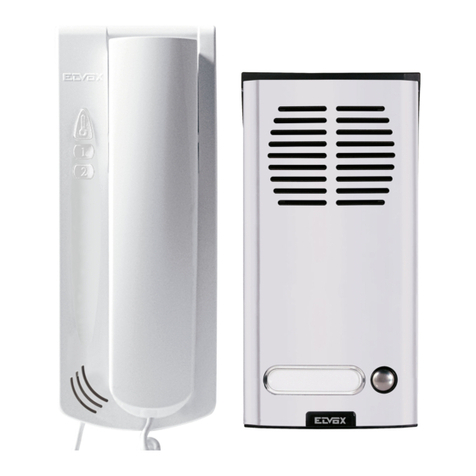
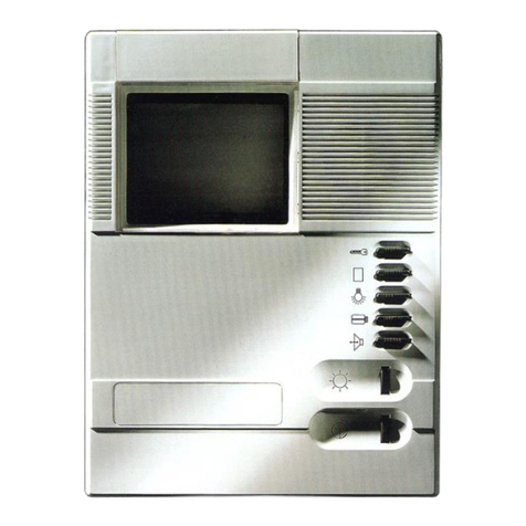
  9. Elvox Petrarca 62KG User manual

Elvox Petrarca 62KG User manual

This manual suits for next models

1

Other Elvox Intercom System manuals

Elvox Vimar K40517G.01 User guide

Elvox

Elvox Vimar K40517G.01 User guide

Elvox ART. 805N/T User manual

Elvox

Elvox ART. 805N/T User manual

Elvox 661C User manual

Elvox

Elvox 661C User manual

Elvox 41018 Assembly instructions

Elvox

Elvox 41018 Assembly instructions

Elvox 68TU/930 User manual

Elvox

Elvox 68TU/930 User manual

Elvox PETRARCA 6209 User manual

Elvox

Elvox PETRARCA 6209 User manual

Elvox GIOTTO 6302/A User manual

Elvox

Elvox GIOTTO 6302/A User manual

Elvox PETRARCA 6029 User manual

Elvox

Elvox PETRARCA 6029 User manual

Elvox Giotto 6344 User manual

Elvox

Elvox Giotto 6344 User manual

Elvox Vimar 40540 Mounting instructions

Elvox

Elvox Vimar 40540 Mounting instructions

Elvox 0930/000.04 User manual

Elvox

Elvox 0930/000.04 User manual

Elvox 637T User manual

Elvox

Elvox 637T User manual

Elvox 12F3 User manual

Elvox

Elvox 12F3 User manual

Elvox 8870 User manual

Elvox

Elvox 8870 User manual

Elvox 6931 Assembly instructions

Elvox

Elvox 6931 Assembly instructions

Elvox 6604 User manual

Elvox

Elvox 6604 User manual

Elvox Giotto 6344 User manual

Elvox

Elvox Giotto 6344 User manual

Elvox 6611 User manual

Elvox

Elvox 6611 User manual

Elvox 3300 User manual

Elvox

Elvox 3300 User manual

Elvox 637G User manual

Elvox

Elvox 637G User manual

Elvox Digibus Galileo Series Guide

Elvox

Elvox Digibus Galileo Series Guide

Elvox 6680/C17 Assembly instructions

Elvox

Elvox 6680/C17 Assembly instructions

Elvox PETRARCA 6020 User manual

Elvox

Elvox PETRARCA 6020 User manual

Elvox VIMAR K7549.R User guide

Elvox

Elvox VIMAR K7549.R User guide

Popular Intercom System manuals by other brands

Videx VRDK1 (25H) Technical manual

Videx

Videx VRDK1 (25H) Technical manual

Auta COMPACT VISUALTECH manual

Auta

Auta COMPACT VISUALTECH manual

Aiphone LC-10S instructions

Aiphone

Aiphone LC-10S instructions

Aiphone PD-1 instructions

Aiphone

Aiphone PD-1 instructions

Aiphone JF-DVF-HID-I instructions

Aiphone

Aiphone JF-DVF-HID-I instructions

Comelit 4893M Technical manual

Comelit

Comelit 4893M Technical manual

MGL Avionics V16 manual

MGL Avionics

MGL Avionics V16 manual

SSS Siedle BVI 750-0 Installation & programming

SSS Siedle

SSS Siedle BVI 750-0 Installation & programming

urmet domus AIKO 1716/1 quick start guide

urmet domus

urmet domus AIKO 1716/1 quick start guide

urmet domus IPerVoice 1039 Installation

urmet domus

urmet domus IPerVoice 1039 Installation

Alpha Communications STR QwikBus TT33-2 Installation, programming, and  user's manual

Alpha Communications

Alpha Communications STR QwikBus TT33-2 Installation, programming, and user's manual

Monacor ICM-20H instruction manual

Monacor

Monacor ICM-20H instruction manual

Logenex A202CR Installation & programming

Logenex

Logenex A202CR Installation & programming

Quantum QR5 Installation and programming manual

Quantum

Quantum QR5 Installation and programming manual

EVGA XR1 quick guide

EVGA

EVGA XR1 quick guide

CyberData 011211 series Installation quick reference

CyberData

CyberData 011211 series Installation quick reference

Vidos duo M1021 user manual

Vidos

Vidos duo M1021 user manual

Savant DOR-SMS-00 Deployment guide

Savant

Savant DOR-SMS-00 Deployment guide

manuals.online logo
manuals.online logoBrands
  • About & Mission
  • Contact us
  • Privacy Policy
  • Terms and Conditions

Copyright 2025 Manuals.Online. All Rights Reserved.

Cod. S6I.62K.G00 RL.01 12/2011
PDGB EFI
MANUALE PER IL COLLEGAMENTO E L’USO - INSTALLATION AND OPERATION MANUAL - MANUEL POUR LA CONNEXION ET L’EMPLOI
INSTALLATION UND BEDIENUNGSANLEITUNG - MANUAL PARA EL CONEXIONADO Y EL USO -MANUAL DE INSTALAÇÃO E UTILIZAÇÃO
Art. 62KG - 62KG/2
TÜRSPRECHANLAGE FÜR EIN- ODER ZWEIFAMILIEN-
HÄUSER MIT EXTERNSPRECHSTELLE ART. 930G
PORTERO ELÉCTRICO UNIFAMILIAR O BIFAMILIAR CON
APARATO EXTERNO ART. 930G
PORTEIRO ELÉCTRICO UNIFAMILIAR OU BIFAMILIAR
COM POSTO EXTERNO ART. 930G
PORTIERE ELETTRICO UNIFAMILIARE E BIFAMILIARE
CON POSTO ESTERNO ART. 930G
AUDIO DOOR ENTRY SYSTEM FOR SINGLE AND DOU-
BLE RESIDENCE WITH SPEECH UNIT TYPE 930G
PORTIER ÉLECTRIQUE POUR UNE VILLA SIMPLE OU
VILLA AVEC DEUX APPARTEMENTS AVEC POSTE EX-
TERNE ART. 930G
Art. 62KG - 62KG/2
Il prodotto è conforme alla direttiva europea 2004/108/CE, 2006/95/CE e successive.
Product is according to EC Directive 2004/108/CE, 2006/95/CE and following norms.
Le produit est conforme à la directive européenne 2004/108/CE, 2006/95/CE et suivantes.
Das Produkt entspricht den europäischen Richtlinien 2004/108/CE, 2006/95/CE und Nachfolgenden.
El producto es conforme a la directiva europea 2004/108/CE, 2006/95/CE y sucesivas.
O produto está conforme a directiva europeia 2004/108/CE, 2006/95/CE e seguintes.
62KG - 62KG/2
2/12
CH S 231
C
2
1
3
AS
4
C1
D
B
120
PRI
*
CH
E
G
E
A2
2
3
6
7
1
2
3
6
7
1
CH S 231
C
2
1
3
AS
4
C1
D
B
120
PRI
*
E
G
A1
2
3
6
7
1
PORTIERE ELETTRICO BIFAMILIARE
ART. 62KG/2
AUDIO DOOR ENTRY SYSTEM FOR DOUBLE RE-
SIDENCE ART. 62KG/2
PORTIER ÉLECTRIQUE POUR UNE VILLA AVEC
DEUX APPARTEMENTS ART. 62KG/2
TÜRSPRECHANLAGE FÜR
ZWEI-FAMILIENHÄUSER ART. 62KG/2
PORTERO ELÉCTRICO BIFAMILIAR ART. 62KG/2
PORTEIRO ELÉCTRICO BIFAMILIAR ART. 62KG/2
RETE-MAINS
RÉSEAU-NETZ
RED-REDE
Trasformatore
Transformer
Transformateur
Transformator
Transformador
Art. M832
N. SI581
PORTIERE ELETTRICO UNIFAMILIARE ART. 62KG
AUDIO DOOR ENTRY SYSTEM FOR SINGLE
RESIDENCE ART. 62KG
PORTIER ÉLECTRIQUE POUR UNE VILLA
SIMPLE ART. 62KG
TÜRSPRECHANLAGE FÜR EIN-FAMILIENHÄUSER
ART. 62KG
PORTERO ELÉCTRICO UNIFAMILIAR ART. 62KG
PORTEIRO ELÉCTRICO UNIFAMILIAR ART. 62KG
RETE-MAINS
RÉSEAU-NETZ
RED-REDE
Citofono
Phone
Poste
Haustelefon
Interfono
Telefone
Art. 62K0
Trasformatore
Transformer
Transformateur
Transformator
Transformador
Art. M832
N. SI581
Citofono
Phone
Poste
Haustelefon
Interfono
Telefone
Art. 62K0
Citofono
Phone
Poste
Haustelefon
Interfono
Telefone
Art. 62K0
62KG - 62KG/2
3/12
2
5
6
3
2
3
6
7
1
A1- TARGA ART. 8911
A2- TARGA ART. 8912
B- PULSANTE SUPPLEMENTARE SER-
RATURA
C- SERRATURA ELETTRICA 12V~
D- POSTO ESTERNO ART. 930G
E- PULSANTI
G- LED DI ILLUMINAZIONE CARTELLINO
PORTANOMI
A1- ENTRANCE PANEL ART. 8911
A2- ENTRANCE PANEL ART. 8912
B- ADDITIONAL PUSH-BUTTON FOR LOCK
C- 12V A.C. ELECTRIC LOCK
D- SPEECH UNIT ART. 930G
E- PUSH-BUTTONS
G- NAME-TAG LIGHTING LED
A1- PLAQUE DE RUE ART. 8911
A2- PLAQUE DE RUE ART. 8912
C- POUSSOIR SUPPLÉMENTAIRE GÂCHE
D- GÂCHE ÉLECTRIQUE 12V C.A.
B- POSTE EXTERNE ART. 930G
E- POUSSOIRS
G- LED D'ÉCLAIRAGE PORTE-NOMES
A1 - TÜRSPRECHSTELLE ART. 8911
A2 - TÜRSPRECHSTELLE ART. 8912
C - ZÜZATZTLICHE TÜRÖFFNERTASTE
D - ELEKTRISCHER TÜRÖFFNER 12V~
B- AUßENSTELLE ART. 930G
E- TASTEN
G- BELEUCHTUNGSLED DES NAMEN-
SCHILDS
A1 - PLACA ART. 8911
A2 - PLACA ART. 8912
C - PULSADOR SUPLEMENTARIO
CERRADURA
D- CERRADURA ELÉCTRICA 12V~
B - APARATO EXTERNO ART. 930G
E- PULSADORES
G- LED DE ILUMINACIÓN DE LA TARJETA
PORTANOMBRES
A1- BOTONEIRA ART. 8911
A2- BOTONEIRA ART. 8912
C- BOTÃO SUPLEMENTAR DE TRINCO
D- TRINCO ELÉCTRICO 12V~
B - POSTO EXTERNO ART. 930G
E- BOTÕES
G- LED DE ILUMINAÇÃO DO CARTÃO
PORTANOMES
Ripetitore di chiamata
Call repeater
Répétiteur d'appel
Lautsprecher für
Rufverdoppelung
Repetidor de llamada
Repetidor de chamada
Art. 2/841
Citofono
Phone
Poste
Haustelefon
Interfono
Telefone
Art.. 62K0
OPTIONAL
N.B.
Nel caso di ronzio sulla fonica
spostare nel posto esterno
Art. 930G, il filo di alimenta-
zione della serratura, dal mor-
setto 4 al morsetto AS.
In case of summing noise on
the audio line, displace (on
the speech unit type 930G)
the supply voltage wire of the
door lock from terminal 4 to
terminal AS.
En cas de bourdonnement
sur la phonique déplacer le fil
d’alimentation de la gâche
dans le poste externe Art.
930G, de la borne 4 à la
borne As.
Falls ein Brummgeräusch auf
der Audiolinie gibt, bei der
Aussenstelle Art. 930G den
Versorgungsdraht des Tür-
schlosses von Klemme 4 an
Klemme AS ersetzen.
En caso de zumbido en la fó-
nica desplazar en el aparato
externo Art. 930G el hilo de
alimentación de la cerradura
del borne 4 al borne AS.
No cso de ruido na fónica de-
splazar no posto externo Art.
930G o fio de alimentação do
trinco do terminal 4 ao termi-
nal AS.
*
I cavi di alimentazione (230V) e i cavi 12
o 15 Vca vanno su canalizzazioni sepa-
rate dagli altri conduttori per non determi-
nare disturbi di induzione. I cavi 12 o 15
Vca vanno collegati direttamente ai mor-
setti 3 e 4 del posto esterno Art. 930G.
The power supply cables (230 V) and the
12 or 15 Vac cables should run through
separate ducts from the other conductors,
so as not to cause interference by induc-
tion. The 12 or 15 Vac cables should be
connected directly to the terminals 3 and
4 on the speech unit Art. 930G.
Les câbles d'alimentation (230 V) et les
câbles de 12 ou 15 Vca vont sur des con-
duites séparées des autres conducteurs
pour éviter des phénomènes d'induction.
Les câbles de 12 ou 15 Vca doivent être
reliés directement aux bornes 3 et 4 du
micro haut-parleur Art. 930G.
Die Versorgungskabel (230V) und die 12
bzw. 15 Vac Kabel sind in von anderen
Leitern separaten Kanälen zu verlegen,
um Störungen durch Induktionsströme
vorzubeugen. Die 12 bzw. 15 Vca Kabel
sind direkt an die Klemmen 3 und 4 der
Außenstelle Art. 930G anzuschließen.
Los cables de alimentación (230 V) y los
cables de 12 o 15 Vca deben instalarse
en canaletas separadas de los demás
conductores para evitar interferencias por
inducción. Los cables de 12 o 15 Vca
deben conectarse directamente a los bor-
nes 3 y 4 del aparato externo Art. 930G.
Os cabos de alimentação (230V) e os
cabos de 12 ou 15 Vca vão para canali-
zações separadas dos outros condutores
para não determinar distúrbios de indu-
ção. Os cabos de 12 ou 15 Vca são di-
rectamente ligados aos bornes 3 e 4 do
posto externo Art. 930G.
Sezione conduttori - Conductor section - Sections des conducteurs
Leiterquerchnitt - Secciones conductores - Secção condutores
Conduttori-Conductors Ø fino a 50m-Ø up to 50m Ø fino a 100m-Ø up to 100m Ø fino a 200m-Ø up to 200m
Conductors-Leitungslänge Ø jusqu’à 50m-Ø bis 50m Ø jusqu’à 100m.-Ø bis 100m Ø jusqu’à 200m.-Ø bis 200m
Conductores-Condutores Øhasta 50m - até 50m Ø hasta 100m - até 100m Ø hasta 200m - até 200m
Comune (3)
Common (3)
Commun (3)
Gemeinsame (3) 0,5 mm20,75 mm21,5 mm2
Común (3)
Commun (3)
0 - 12 0,25 mm20,5 mm21 mm2
62KG - 62KG/2
4/12
C
2
1
3
AS
4
C1
D
B
120
PRI
*
G
E
CHCH S 231
321
CH S
CH
2
3
8
6
7
4/5
B
1
6S
C
A
2
6E
6P
6
5
3
7
AU
1
A
N. SI572
RETE-MAINS
RÉSEAU-NETZ
RED-REDE
Citofono
Phone
Poste
Haustelefon
Interfono
Telefone
Art. 8872
Art. 8875
Trasformatore
Transformer
Transformateur
Transformator
Transformador
Art. M832
Citofono
Phone
Poste
Haustelefon
Interfono
Telefone
Art. 6200
SCHEMA DI COLLEGAMENTO PER
IMPIANTO CITOFONICO MONO O PLU-
RIFAMILIARE CON POSTO ESTERNO
ART. 930G
WIRING DIAGRAM FOR SINGLE OR
MULTIRESIDENCE AUDIO ENTRANCE
PANEL SYSTEM WITH SPEECH UNIT
ART. 930G
SCHÉMA DE RACCORDEMENT POUR
PORTIER AUDIO MONO OU PLURIFA-
MILIAL AVEC POSTE EXTERNE ART.
930G.
SCHALTPLAN FÜR EIN- ODER
MEHRFAMILIENHAUS MIT AUDIO-TÜR-
SPRECHANLAGE UND AUßEN-
SPRECHSTELLE ART. 930G.
ESQUEMA DE CONEXIONADO PARA
INSTALACIÓN DE PORTERO AUDIO
MONO O PLURIFAMILIAR CON
APARATO EXTERNO ART. 930G.
ESQUEMA DE LIGAÇÃO PARA INSTA-
LAÇÃO DE PORTEIRO AUDIO MONO
OU PLURIFAMILIAR COM POSTO EX-
TERNO ART. 930G.
62KG - 62KG/2
5/12
A- TARGA ESTERNA AUDIO
SERIE 1200, 8000, 3300, 8100,
PATAVIUM, PORTALETTERE
B- PULSANTE SUPPLEMENTARE SER-
RATURA
C- SERRATURA ELETTRICA 12V~
D- POSTO ESTERNO ART. 930G
E- PULSANTI
G- LED DI ILLUMINAZIONE CARTELLINO
PORTANOMI
A- ENTRANCE PANEL
SERIE 1200, 8000, 3300, 8100,
PATAVIUM, MAIL BOX
B- ADDITIONAL PUSH-BUTTON FOR LOCK
C- 12V A.C. ELECTRIC LOCK
D- SPEECH UNIT ART. 930G
E- PUSH-BUTTONS
G- NAME-TAG LIGHTING LED
A- PLAQUE DE RUE
SERIE 1200, 8000, 3300, 8100,
PATAVIUM, BOÎTE AUX LETTRES
C- POUSSOIR SUPPLÉMENTAIRE GÂCHE
D- GÂCHE ÉLECTRIQUE 12V C.A.
B- POSTE EXTERNE ART. 930G
E- POUSSOIRS
G- LED D'ÉCLAIRAGE PORTE-NOMES
A- TÜRSPRECHSTELLE SERIE 1200, 8000,
3300, 8100, PATAVIUM, BRIEFKASTEN
C - ZÜZATZTLICHE TÜRÖFFNERTASTE
D - ELEKTRISCHER TÜRÖFFNER 12V~
B- AUßENSTELLE ART. 930G
E- TASTEN
G- BELEUCHTUNGSLED DES
NAMENSCHILDS
A- PLACA SERIE 1200, 8000, 3300, 8100,
PATAVIUM, BUZÓN
C - PULSADOR SUPLEMENTARIO CER-
RADURA
D- CERRADURA ELÉCTRICA 12V~
B - APARATO EXTERNO ART. 930G
E- PULSADORES
G- LED DE ILUMINACIÓN DE LA TARJETA
A- BOTONEIRA SERIE 1200, 8000, 3300,
8100, PATAVIUM, CAIXA DE CORREIO
C- BOTÃO SUPLEMENTAR DE TRINCO
D- TRINCO ELÉCTRICO 12V~
B - POSTO EXTERNO ART. 930G
E- BOTÕES
G- LED DE ILUMINAÇÃO DO CARTÃO
PORTANOMES
Sezione conduttori - Conductor section - Sections des conducteurs
Leiterquerchnitt - Secciones conductores - Secção condutores
Conduttori-Conductors Ø fino a 50m-Ø up to 50m Ø fino a 100m-Ø up to 100m Ø fino a 200m-Ø up to 200m
Conductors-Leitungslänge Ø jusqu’à 50m-Ø bis 50m Ø jusqu’à 100m.-Ø bis 100m Ø jusqu’à 200m.-Ø bis 200m
Conductores-Condutores Øhasta 50m - até 50m Ø hasta 100m - até 100m Ø hasta 200m - até 200m
Comune (3)
Common (3)
Commun (3)
Gemeinsame (3) 0,5 mm20,75 mm21,5 mm2
Común (3)
Commun (3)
0 - 12 0,25 mm20,5 mm21 mm2
N.B.
Nel caso di ronzio sulla fonica
spostare nel posto esterno
Art. 930G, il filo di alimenta-
zione della serratura, dal mor-
setto 4 al morsetto AS.
In case of summing noise on
the audio line, displace (on
the speech unit type 930G)
the supply voltage wire of the
door lock from terminal 4 to
terminal AS.
En cas de bourdonnement
sur la phonique déplacer le fil
d’alimentation de la gâche
dans le poste externe Art.
930G, de la borne 4 à la
borne As.
Falls ein Brummgeräusch auf
der Audiolinie gibt, bei der
Aussenstelle Art. 930G den
Versorgungsdraht des Tür-
schlosses von Klemme 4 an
Klemme AS ersetzen.
En caso de zumbido en la fó-
nica desplazar en el aparato
externo Art. 930G el hilo de
alimentación de la cerradura
del borne 4 al borne AS.
No cso de ruido na fónica de-
splazar no posto externo Art.
930G o fio de alimentação do
trinco do terminal 4 ao termi-
nal AS.
*
I cavi di alimentazione (230V) e i cavi 12
o 15 Vca vanno su canalizzazioni sepa-
rate dagli altri conduttori per non determi-
nare disturbi di induzione. I cavi 12 o 15
Vca vanno collegati direttamente ai mor-
setti 3 e 4 del posto esterno Art. 930G.
The power supply cables (230 V) and the
12 or 15 Vac cables should run through
separate ducts from the other conductors,
so as not to cause interference by induc-
tion. The 12 or 15 Vac cables should be
connected directly to the terminals 3 and
4 on the speech unit Art. 930G.
Les câbles d'alimentation (230 V) et les
câbles de 12 ou 15 Vca vont sur des con-
duites séparées des autres conducteurs
pour éviter des phénomènes d'induction.
Les câbles de 12 ou 15 Vca doivent être
reliés directement aux bornes 3 et 4 du
micro haut-parleur Art. 930G.
Die Versorgungskabel (230V) und die 12
bzw. 15 Vac Kabel sind in von anderen
Leitern separaten Kanälen zu verlegen,
um Störungen durch Induktionsströme
vorzubeugen. Die 12 bzw. 15 Vca Kabel
sind direkt an die Klemmen 3 und 4 der
Außenstelle Art. 930G anzuschließen.
Los cables de alimentación (230 V) y los
cables de 12 o 15 Vca deben instalarse
en canaletas separadas de los demás
conductores para evitar interferencias por
inducción. Los cables de 12 o 15 Vca
deben conectarse directamente a los bor-
nes 3 y 4 del aparato externo Art. 930G.
Os cabos de alimentação (230V) e os
cabos de 12 ou 15 Vca vão para canali-
zações separadas dos outros condutores
para não determinar distúrbios de indu-
ção. Os cabos de 12 ou 15 Vca são di-
rectamente ligados aos bornes 3 e 4 do
posto externo Art. 930G.
62KG - 62KG/2
6/12
Das Netzgerät ist an einem trockenen und staubfreien Ort unter Vermeidung der Nähe von Wärmequellen zu installieren. Zur Er-
leichterung von Kontrollen und Einstellungen sollte der Aufstellungsort gut zugänglich sein. Das Netzgerät mit den beigepackten
Dübeln an der Wand befestigen oder in einen Verteiler mit DIN-Omegaschiene einsetzen. Vor dem Anschluß an das Stromnetz
mit einem Testgerät sicherstellen, daß die Leiter nicht unterbrochen oder kurzgeschlossen sind. Zur größeren Sicherheit des An-
wenders werden alle Apparate mit Niederspannung betrieben und durch einen stark isolierenden Transformator vom Stromnetz
getrennt. In jedem Fall sollte jedoch zwischen dem Stromnetz und der Anlage ein Fehlerstromschutzschalter von angemessener
Stromfestigkeit installiert werden.
Die Produkte sind konform zu den CE-Markenzeichen und Richtlinien:
- zu den EG-Richtlinien 2004/108/CE und Folgenden
- zu den EG-Richtlinien 2006/95/CE (73/23/CEE).
Die Netzgeräte, die die vom Art. 411.1.2.2 der CEI 64-8 (Ausgabe 2003) Norm Vorgesehene Fähigkeiten respektie-
ren, eine SELV Quelle bestellen.
The power supply must be installed in a dry place away from direct heat or dust. Ensure easy access for inspection and mainte-
nance. Secure the unit to the wall with the anchor bolts provided or insert it into a rack with a omega DIN bar. Before connecting
the unit use a tester to make sure that the cables are not broken or short-circuited. For user safety, the equipment operates at a
low voltage and is separated from the mains by a high-insulation transformer. We recommend installation of an overload cutout
of appropriate capacity between the mains and the unit.
Product is according to CE mark and directives:
- EC Directives 2004/108/CE and following norms.
- EC Directives 2006/95/CE (73/23/CEE).
Power supply units constitute SELV sources in compliance with the requirements stipulated in Article 411.1.2.2 of CEI
standard 64-8 (ed. 2003).
L'alimentatore andrà posto in un luogo asciutto e lontano da polvere e fonti di calore. Al fine di facilitare controlli e messe a punto
curare che il luogo sia facilmente accessibile. Fissare a parete l'alimentatore mediante i tasselli in dotazione o inserendolo in ap-
posito quadro con barra DIN ad omega. Prima di procedere al collegamento accertarsi mediante un normale tester che i condut-
tori non siano interrotti o in corto circuito. Per una maggiore sicurezza dell'utente, tutte le apparecchiature funzionano in bassa
tensione e sono separate dalla rete da un trasformatore ad alto isolamento. È opportuno comunque interporre tra la rete di ali-
mentazione e l'apparecchio un interruttore magnetotermico di portata adeguata.
I prodotti sono conformi al marchio CE e alle direttive:
- Alla direttiva europea 2004/108/CE e successive.
- Alla direttiva europea 2006/95/CE (73/23/CEE).
Gli alimentatori costituiscono una sorgente SELV rispettando i requisiti previsti dall’articolo 411.1.2.2 della norma CEI 64-8
(ed. 2003).
INSTALLAZIONE DEGLI ALIMENTATORI - POWER SUPPLY INSTALLATION
INSTALLATION DES ALIMENTATIONS - INSTALLATION DER NETZGERÄTE
INSTALACIÓN DE LOS ALIMENTADORES - INSTALACIÓN DE LOS ALIMENTADORES
L’alimentation devra être placée dans un endroit sec, à l’abri de la poussière et loin de toute source de chaleur. Afin de faciliter
les contrôles et les mises au point, choisir un endroit facilement accessible. Fixer l’alimentation sur le mur à l’aide des chevilles
fournies de série ou en l’insérant dans un tableau approprié avec barre DIN en oméga. Avant d’effectuer le raccordement,
s’assurer, à l’aide d’un testeur normal, que les conducteurs ne sont pas interrompus ou en court-circuit. Pour une plus grande sé-
curité de l’utilisateur, tous les appareils fonctionnent en basse tension et sont séparés du réseau par un transformateur à haute
isolation. Il convient dans tous les cas d’interposer un disjoncteur magnétothermique d’une portée appropriée entre le réseau
d’alimentation et l’appareil.
Les produits sont conformes à la marque CE et à les directives :
- À la directive européenne 2004/108/CE et suivantes.
- À la directive européenne 2006/95/CE (73/23/CEE).
Les alimentations constituent une source SELV et respectent les qualités requises par l’article 411.1.2.2 de la norme CEI
64-8 (ed. 2003).
El alimentador tiene que ser colocado en un lugar seco y lejos del polvo y fuentes de calor. Al fin de facilitar controles y puestas
a punto el lugar de la instalación debe ser fácilmente accesible.Fijar a la pared el alimentador por medio de tacos en dotación o
insertándolo en un cuadro apropiado con barra DIN a omega. Ante de proceder al conexionado asegurarse, por medio de un nor-
mal tester, que los conductores no sean interrumpidos o en cortocircuito Para una mayor seguridad del usuario, todas los apa-
ratos funcionan a baja tensión y son separados de la red por un transformador a alta isolación. Es oportuno de todas maneras
poner entre la red de alimentación y el aparato un interruptor magnetotérmico de portada adecuada.
Los productos son conformes a la marca CE y a las normas :
- A las normas europeas 2004/108/CE y siguientes
- A las normas europeas 2006/95/CE (73/23/CEE).
Los alimentadores constituyen una fuente SELV y respectan los requisitos previstos por el artículo 411.1.2.2 de la
norma CEI 64-8 (ed. 2003).
62KG - 62KG/2
7/12
Per aprire il citofono
To open interphone
Pour ouvrir le poste
Öffnen des Haustelefone
Para abrir el teléfono
Para abrir o telefono
INSTALLAZIONE DEL CITOFONO - PHONE INSTALLATION - INSTALLATION DU POSTE
HAUSTELEFON INSTALLIERUNG - INSTALACION DO TELÉFONO- INSTALAÇÃO DO TELEFONE
1 Open the interphone, split the cover from the bottom ma-
king pressure on the lower side of the cover.
2 Fix the interphone to the rectangular, vertical flush-
mounted back-box with the 2 screws supplied, or fix the
screws with the ø5 expansion plugs. Connect the wires
to the terminals. You are advised to fix the top of the in-
terphone at a height of about 1.5 m above the ground.
1 Das Haustelefon öffnen, den Deckel vom Boden entfer-
nen durch Drücken auf die Unterseite des Deckels.
2 Das Haustelefon mit den zwei mitgelieferten Schrauben
am rechteckigen senkrechten UP-Gehäuse oder mit
Spreizdübeln ø5 befestigen. Die Leiter an die Klemmen-
leiste anschließen. Es wird empfohlen, die obere Kante
des Türsprechgeräts etwa 1,5 m über dem Fußboden zu
montieren.
1 Abrir o telefone, afastar a tampa do fundo fazendo força
no lado inferior da tampa.
2 Fixar a base do telefone na caixa rectangular vertical an-
teriormente encastrada através de 2 parafusos forneci-
dos ou aparafusar os mesmos nas buchas de ø5.
Efectuar as ligações nos bornes.
Aconselha-se a fixar a parte superior do telefone a uma
altura de 1,5 m do pavimento.
1 Aprire il citofono, separare il coperchio dal fondo facendo
forza nel lato inferiore del coperchio.
2 Fissare il citofono su scatola rettangolare verticale incas-
sata per mezzo delle 2 viti in dotazione, oppure fissare
le viti con i tasselli ad espansione ø5. Collegare i fili ai
morsetti.
Si consiglia di fissare la parte superiore del citofono ad
un’altezza di m. 1,5 circa dal pavimento.
1 Ouvrir le poste d'appartement, séparer le couvercle du
fond en faisant force du côté inférieur du couvercle.
2 Fixer le portier sur un boîtier rectangulaire vertical enca-
stré avec les 2 vis livrées en standard ou fixer ces vis
sur des chevilles à expansion ø5. Effectuer les raccorde-
ments aux bornes. On conseille de murer le côté supé-
rieur à environ 1,5 m du niveau du sol.
1 Abrir el teléfono, separar la tapa del fondo apretando en
el lado inferior de la tapa.
2 Fijar el teléfono en la caja rectangular vertical empotrada
mediante los 2 tornillos en dotación, o fijar los tornillos
con los tacos de expansión ø5. Conectar los hilos a los
bornes. Se aconseja fijar la parte superior del teléfono a
aproximadamente 1,5 m del suelo.
ART. 62K0
O alimentador deverá ser colocado num local seco e ao abrigo do pó e de fontes de calor. Para facilitar os controlos e as afi-
nações, certifique-se de que o local é de fácil acesso. Fixe o alimentador à parede com as buchas fornecidas ou inserindo-o
num quadro próprio com calha DIN tipo omega. Antes de proceder à ligação certifique-se, com um tester normal, de que os
condutores não estão interrompidos ou em curto-circuito. Para uma maior segurança do utilizador, todos os aparelhos fun-
cionam em baixa tensão e estão separados da rede por um transformador de alto isolamento. Em todo o caso, convém co-
locar entre a rede de alimentação e o aparelho um interruptor magnetotérmico de capacidade adequada.
Os produtos estão em conformidade com a marca CE e as directivas:
- Directiva europeia 89/336/CEE e seguintes.
- Directiva europeia 2006/95/CE (73/23/CEE).
Os alimentadores constituem uma fonte SELV e cumprem os requisitos previstos no artigo 411.1.2.2 da norma
CEI 64-8 (ed. 2003).
La produzione dell’alimentatore è sotto costante sorveglianza:
Production is subject to costant surveillance:
La production est sous constante surveillance:
Die Netzgerätserzeugung ist unter ständiger Aufsicht:
A fabrico do alimentador está sob a constante vigilância de:
A produção do alimentador está sob vigilância constante:
DVE
62KG - 62KG/2
8/12
INSTALLAZIONE DELLE TARGHE - MOUNTING INSTRUCTIONS OF ENTRANCE PANEL
INSTALLATION DE LA PLAQUE DE RUE - MONTAGEHINWEISE FÜR TÜRSPRECHSTELLE
INSTALACION DE LA PLACA EXTERNA - INSTALAÇÃO DA BOTONEIRA EXTERIOR
Un die Frontplatte vom Up-gehäuse zu entfernen, gehen
Sie wie folgt vor:
1: Schraube am unteren Profilrand bis zum Anschlag
mit vergesehenem Schlüssel aufdrehen.
2: Das Profil unten um 2 cm. abheben, die Frontplatte
nach oben schieben und ausrasten.
3-4: Frontplatte nach unten ziehen und abhehmen.
Para separar le placa desde la caja de empotre seguir
estas operaciones.
1: Aflojar el tornillo puesto sobre el borde inferior de la
placa hasta el final del filete con la llave especial
provista.
2: Alejar de 2 cm. la orilla inferior de la placa tenién-
dola empujada hacia arriba.
3-4: Separar la placa jalàndola hacia abajo.
To separe front plate from back box, follow there instruc-
tions:
1: Loosen screw in lower border of front plate to limit
of thread, using special key provided.
2: Lift lower border of front plate slightly out wards and
upwards.
3-4: Detach front plate by pulling it downwards.
Per separare la placca dalla scatola da incasso esegui-
re le seguenti operazioni:
1: Allentare la vite posta sul bordo inferiore della plac-
ca fino a fine corsa a mezzo della chiavetta in do-
tazione.
2: Allontanare di 2 cm. il bordo inferiore della placca
tenendola spinta verso l'alto.
3-4: Togliere la placca tirandola verso il basso.
Para separar a placa botoneira da caixa, seguir as
seguintes operações:
1: Desapertar o parafuso da parte inferior da placa até
ao fim através de chave especial junta.
2: Afastar 2 cm. a parte inferior da placa mantendo-a
encostada no topo.
3-4: Separar a placa puxando-a baixo e reteira-la.
Pour séparer la plaque de la boîte à encastrer suivre ces
opérations:
1: Desserer la vis placée sur le bord inférieur de la
plaque jusq'à la butée en utilisant la clé spéciale
fournie dans l'emballage.
2: Soulever de 2 cm le bord inférieur de la plaque en
la tenant poussée vers le haut.
3-4: Enlever la plaque en la tirant vers le bas.
Per accedere al cartellino portanomi togliere il fermacartellino dal retro come mostra la figura.
To reach name-tag, remove name-tag holder from the back, as shown.
Pour acceder à l'étiquette porte-noms enlever le porte-étiquette de la partie postérieure comme
le montre la figure.
Um das Namensschild zu erhalten, entfernen Sie die Namenschildhalterung von der Rück-
seite, wie dezeigt.
Para acceder a la tarjetita portanombres mover el sujetatarjetita desde atrás como muestra la
figura.
Para ter acesso ao cartão porta-nomes extrair a tampa de plástico que o prende como mostra
a figura.
ESTRAZIONE DEL CARTELLINO PORTANOME - NAME-TAG REMOVING
EXTRACTION DE L'ÉTIQUETTE PORTE - NOMS-HERAUSZIEHEN DES NAMENSSCHIELD
ESTRACCIÓN DE LA TARJETITA PORTANOMBRES - EXTRAÇÃO DO CARTÃO PORTA-NOMES
62KG - 62KG/2
9/12
Morsettiera
Terminal block
Boîte de raccordement
Klemmenleiste
Regleta conexiones
Bornes
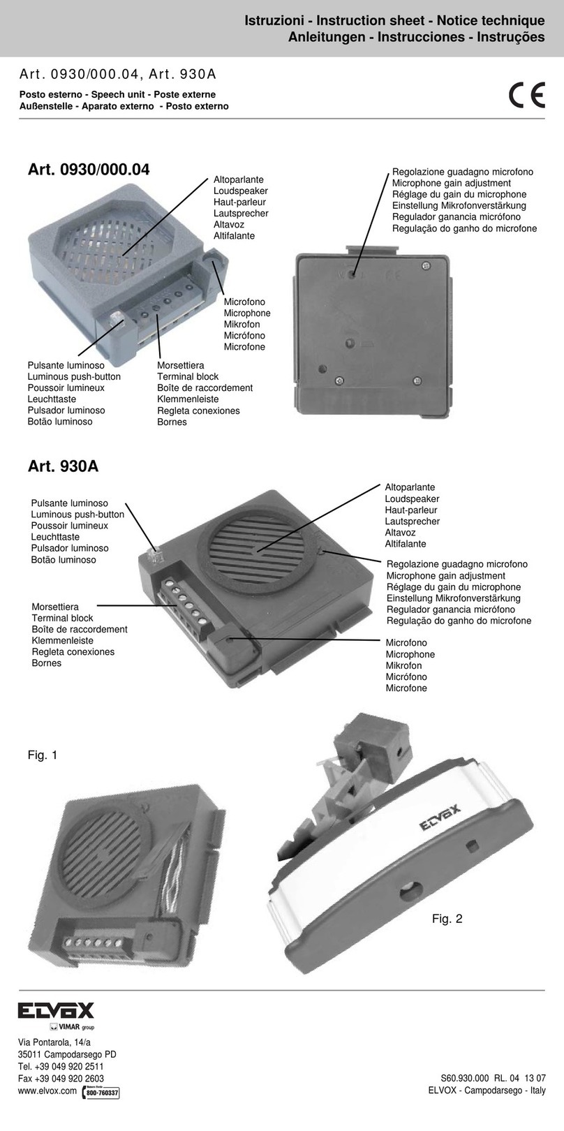
Microfono
Microphone
Kikrofon
Micrófono
Microfone
Altoparlante
Loudspeaker
Haut-parleur
Lautsprecher
Altavoz
Altifalante
Volume interno
Internal volume
Volume intérieur
Lautstärke innen
Volumen interno
Volume interno
Volume esterno
External volume
Volume extérieur
Lautstärke außen
Volumen externo
Volume externo
Fig. 1
Fig. 2
Allontanamento del microfono dall’altoparlante
Questa operazione permette di aumentare notevolmente il volume ed evi-
tare l’effetto LARSEN (fischio). Per spostare il microfono eseguire quanto
segue:
- Aprire lo sportello con la freccia dell'Art. 930G (Fig. 1)
- Sfilare il microfono dalla sue sede.
- Alloggiare il microfono nell’apposita sede ricavata nella parte bassa a de-
stra nella targa. Vedi nella Fig. 2, esempio per inserimento del microfono
in una targa serie 8000.
Averting the microphone from the loudspeaker.
This operation allows you to increase the volume considerably and avoid the
LARSEN effect (whistle).To displace the microphone operate as it follows:
- Open the door with the arrow of Art. 930G (Fig. 1)
- Remove the microphone from its seat.
- Fit the microphone in proper seat on the right lower side of the panel. See
Fig. 2, example for insertion of microphone in an entrance panel series
8000.
Éloignement du microphone dès haut-parleur.
Cette opération permet d’augmenter notablement le volume et d’éviter l’effet
LARSEN (sifflement). Pour déplacer le microphone effectuer les opérations
suivantes :
- Ouvrir la porte avec la flèche de l'Art. 930G (Fig. 1).
- Défiler le microphone de son siège.
- Loger le microphone dans le siège approprié dans la partie inférieure à
droite de la plaque de rue, voir Fig. 2 :’exemple d’insertion du microphone
dans une plaque de rue série 8000.
Entfernung des Mikrofons vom Lautsprecher
Dieser Vorgang ermöglicht die Läutstärke beachtlich zu erhöhen und den
LARSEN Effekt (Pfeifen) zu vermeiden.
Um das Mikrofon zu entfernen gehen Sie folgendermaßen vor:
- Die Abdeckung mit dem Pfeil des Arts. 930G öffnen (Abb. 1).
- Das Mikrofon aus seiner Halterung nehmen
- Das Mikrofon in den entsprechenden Sitz rechts auf der Unterseite des
Klingeltableaus einsetzen. Siehe Beispiel in Abb. 2: Einstecken des Mikro-
fons in einem Klingeltableau Baureihe 8000.
Alejamiento del micrófono del altavoz.
Esta operación permite aumentar considerablemente el volumen y evitar el
efecto LARSEN (silbido).
Par desplazar el micrófono efectuar las siguients operaciones:
- Abrir la puerta con la flecha del Art. 930G (Fig. 1).
- Desfilar el micrófono de su asiento.
- Montar el micrófono en el asiento apropiado a la derecha en la parte infe-
rior de la placa. Ver Fig. 2, ejemplo para la inserción del micrófono en una
placa serie 8000.
Afastamento do microfone do altifalante
Esta operação permite aumentar notávelmente o volume e de evitar o efeito
LARSEN (silbo). Para afastar o microfone proceder do seguinte modo:
- Abrir a tampa do Art. 930G (Fig. 1), de acordo com a seta.
- Retirar o microfone da sua sede.
- Montar o microfone na sede apropriada à direita na parte inferior da bo-
toneira. Ver Fig. 2, exemplo para a inserção do microfone na botoneira da
série 8000.
DESCRIZIONE IMPIANTO DI PORTIERE ELETTRICO CON
POSTO ESTERNO ART. 930G
Questo tipo di impianto si avvale del nuovo posto esterno Art.
930G che è in grado di generare una nota elettronica modulata
per la chiamata dal posto esterno: in questo caso i citofoni utiliz-
zati sono muniti di un altoparlante per la diffusione del suono. Il
collegamento complessivo si ottiene utilizzando un semplice tra-
sformatore che alimenta l'intero impianto.
Per un buon funzionamento dell’impianto si consiglia di eseguire i
collegamenti come mostra lo schema di principio.
PRINCIPIO DI FUNZIONAMENTO
Quando un visitatore preme un pulsante della targa esterna si
sente nel citofono un segnale sonoro: l'utente interno può solle-
vare il microtelefono e conversare con il visitatore senza limiti di
tempo.
DESCRIPTION INSTALLATION POUR PORTIER ÉLECTRIQUE
AVEC POSTE EXTERNE ART. 930G
Ce type d’installation est équipé du nouveau poste extérieur Art. 930G
qui est en mesure d’émettre une note électronique modulée pour
l’appel depuis le poste extérieur: dans ce cas, les postes
d’appartement utilisés sont munis d’un haut-parleur pour la diffusion
du son. Le branchement général s’effectue en utilisant un simple
transformateur qui alimente toute l’installation.
Pour un bon fonctionnement de l’installation on conseille d’effectuer
les connexions selon le schéma de base.
PRINCIPE DE FONCTIONNEMENT
Lorsqu’un visiteur appuie sur une touche de la plaque extérieure, on
entend dans le poste un signal sonore : l’utilisateur intérieur peut
soulever le micro-combiné et converser avec le visiteur sans limite
de temps.
SYSTEM DESCRIPTION WITH SPEECH UNIT ART. 930G
AUDIO DOOR ENTRY SYSTEM
This type of unit makes use of the new external unit (Art. 930G)
which can generate a modulated electronic signal for a call from
the external unit; in this case, the door phones used are supplied
with a loudspeaker for the transmission of the sound. The overall
connections are made using a simple transformer which supplies
the whole system.
For a good installation operation it is advisable to carry out connec-
tions according to the standard diagram.
OPERATING INSTRUCTIONS
When a visitor presses a button on the external plaque, he will hear
a sound on the phone; the user within the building can lift the door
phone and speak to the visitor without any time limit.
BESCHREIBUNG DER ANLAGE MIT AUßENSTELLE ART. 930G
ETÜRSPRECHANLAGE
Für diese Art Anlage wird die neue externe Sprechstelle verwendet,
die in der Lage ist, eine modulierte elektronische Note für den Ruf
von der externen Sprechstelle zu erzeugen: in diesem Fall sind die
verwendeten Haustelefonen mit einem Lautsprecher für die Schalld-
iffusion ausgestattet. Der Gesamtanschluß wird durch Verwendung
eines einfachen Transformators erzielt, der die ganze Anlage ver-
sorgt. Für einen optimalen Installationbetrieb empfiehlt man die An-
schlüße nach den Prinzipschaltplan durchzufüren.
FUNKTIONSWEISE
Wenn ein Besucher auf einen Knopf des externen Klingeltableaus
drückt, ertönt im Haustelefon ein akustisches Signal; der interne Teil-
nehmer kann den Hörer abnehmen und zeitlich unbegrenzt mit dem
Besucher sprechen.
DESCRIÇÃO DA INSTALAÇÃO PARA PORTEIRO ELÉCTRICO
COM POSTO EXTERNOART. 930G
Este tipo de instalação serve-se do novo posto externo Art. 930G que
tem a possibilidade produzir m toque electrónico modulado para a
chamada do posto externo: neste caso os telefones utilizados estão
equipados com um altifalante para a difusão do som. A ligação obtém-
se utilizando o tranformador que alimenta toda a instalação.
Para um bom funcionamento da instalação aconselha-se efectuar as
ligações como mostra o esquema de princípio.
PRINCIPÍO DE FUNCIONAMENTO
Quando um visitante prime o botáo da botoneria externa, ouve no
telefone um sinal sonoro: o utente interno pode levantar o telefone e
conversar com o visitante sem limite de tempo.
DESCRIPCIÓN INSTALACIÓN PARA PORTERO ELÉCTRICO
CON APARATO EXTERNO ART. 930G
Este tipo de instalación utiliza el nuevo aparato externo Art. 930G
que puede generar una nota electrónica modulada para la llamada
del aparato externo: de este modo los interfonos utilizados son
provistos de un altavoz para la difusión del sonido. El conexionado
total se obtiene utilizando un simple transformador que alimenta la
instalación intera.
Para un buen funcionamiento de la instalación se aconseja de eje-
cutar las conexiones como muestra el esquema de principio.
PRINCIPIO DE FUNCIONAMIENTO
Cuando un visitador presiona un pulsador de la placas externa se
oye en el interfono una señal sonora: el usuario interno puede
descolgar el microteléfono y conversar con il visitador sin límites
de tiempo.
10/12
62KG - 62KG/2