4) Premere e mantenere premuti i tasti Ae C no al suono di
una “nota” da parte del citofono che si sta programmando
e l’accensione del led ROSSO con luce ssa.
5) Rilasciare i tasti Ae C
Attenzione: sono disponibili 5s per premere i tasti A e C
(come indicato al punto 4). Se trascorrono i 5s senza premere
i tasti A e C, deve essere ripetuta la procedura dei punti 1,2,3.
6) A questo punto, si attiva la comunicazione tra citofono e
targa e sono a disposizione 25s per effettuare l’associazi-
one del codice ID dalla targa esterna:
- nel caso di targa alfanumerica, digitare il codice ID (lo
stesso codice ID primario assegnato al citofono capo-
gruppo) e confermare con il tasto “campanella”.
- nel caso di targa a pulsanti, premere il pulsante dal quale
si desidera effettuare la chiamata al citofono (lo stesso
pulsante con cui è stato programmato il citofono capo-
gruppo).
Attenzione: Se trascorrono i 25s senza aver portato a ter-
mine la procedura descritta, deve essere ripetuta la procedura
dal punto 1.
Attenzione: Nella programmazione del identicativo ID pri-
mario e secondario i citofoni in programmazione acquisiscono
automaticamente un codice che dipende dall’associazione al
pulsante o codice di chiamata della targa esterna. La corri-
spondenza tra il codici ID primari e i relativi ID secondari è
indicata nella tabella riportata in seguito.
Esempio: Nel caso venga dato l’identicativo ID = 8 ad un
secondo citofono, con la procedura di attribuzione dell’identif-
icativo automatico al secondo citofono, prenderà automatica-
mente l’ID = 72 (vedi tabella).
Quando viene inviata una chiamata all’ID = 8 suoneranno en-
trambi i citofoni e si potrà rispondere da entrambi. Se invece
digito 72 che corrisponde all’identicativo ID assegnato auto-
maticamente dalla procedura, suona e posso rispondere solo
dal citofono su cui è stata fatta la procedura di assegnazione
dell’ID secondario.
Programmazioni manuali
Le programmazioni base del citofono sono le seguenti:
- Programmazionedell’identicativoID, da effettuare sul
citofono che riceve la chiamata singolarmente o sul primo
citofono di un gruppo di citofoni con chiamata contempora-
nea (citofono capogruppo).
- Programmazionedell’identicativoIDsecondario , da
effettuare per i citofoni associati ad un video(citofono) capo-
gruppo.
- Programmazione dei pulsanti programmabili o la modica
della impostazione di default di pulsanti supplementari, per
servizi ausiliari o chiamate intercomunicanti.
Programmazionedell’identicativoID
Per programmare l’identicativo ID procedere come segue:
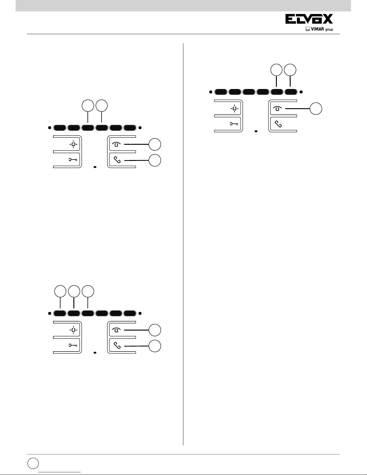
1) Premere il tasto Be mantenere premuto.
2) Premere anche il tasto Ae mantenere premuti i due tasti.
3) Quando il led rosso lampeggia rilasciare i tasti.
4) Premere il tasto C e tenerlo premuto no al suono di una
“nota” da parte del citofono che si sta programmando e l’ac-
censione del led rosso con luce ssa.
5) Rilasciare il tasto C.
Attenzione: sono disponibili 5s per premere il tasto C(come
indicato al punto 4). Se trascorrono i 5s senza premere il tasto
C, deve essere ripetuta la procedura dei punti 1,2,3.
6) A questo punto, si attiva la comunicazione tra citofono e
targa e sono a disposizione 25s per effettuare l’associazi-
one del codice ID dalla targa esterna:
- nel caso di targa alfanumerica, digitare il codice ID prima-
rio e confermare con il tasto “campanella”.
- nel caso di targa a pulsanti, premere il pulsante dal quale
si desidera effettuare la chiamata al citofono.
Attenzione: Se trascorrono i 25s senza aver portato a termine
la procedura descritta, deve essere ripetuta la procedura dal
punto 1.
Attenzione: Se nell’impianto esiste già un citofono/videoci-
tofono con lo stesso codice identicativo associato, la targa
emette un segnale sonoro basso ed è necessario ripetere l’op-
erazione dall’inizio per assegnare un codice diverso.
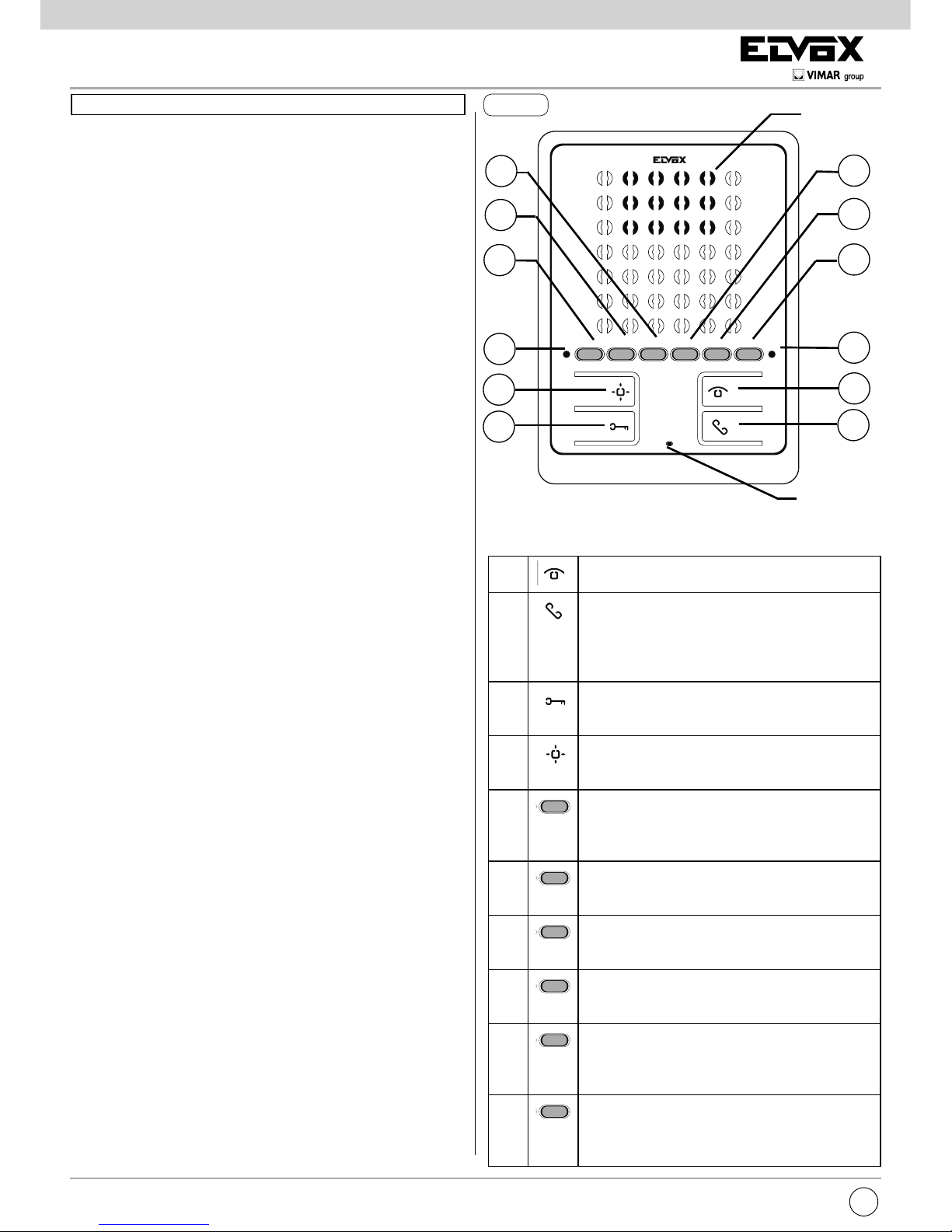
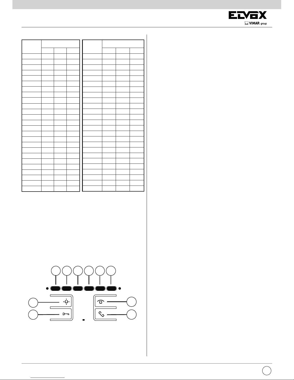
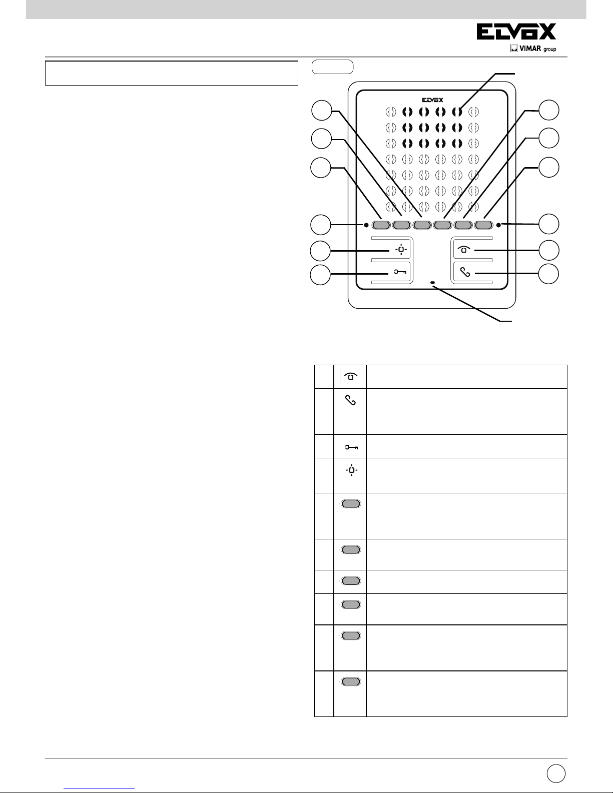
A
B
C
Programmazionedell’identicativoIDSecondario
Per programmare l’identicativo ID secondario procedere
come segue:
1) Premere il tasto Be mantenere premuto.
2) Premere anche il tasto Ae mantenere premuti i due tasti.
3) Quando il led ROSSO lampeggia rilasciare i tasti.