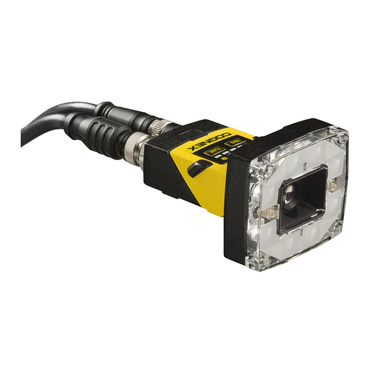
EM Motorsport ADR4 User manual

EM Motorsport Ltd
Unit A4 TelfordRoad
Bicester
Oxon,OX264LD
U.K.
Tel: +44 (0) 1869241977
EM Motorsport Ltd®
All rights reserved. No reproductionof this document,use and communication of its contents may be made without written authorisation.
Specificationsubjectto changewithout notice
ADR4 InstallationManual
Revision
Reason
Author
Date
Checkby
2.0
ADR4 version, added channel list
V. Dariol
21/08/2019
2.1
Added serial terminal commands lists.
V. Dariol
22/08/2019
2.2
Added Test in the command list description at
paragraph 2.3
V. Dariol
02/10/2019
2.3
General Revision + Removed CAN Protocol
I. Gamboa
28/01/2020
2.4
Clarification on connector pin 6 and 13 both
galvanically connected to internal ground.
V. Dariol
06/11/2020
2.5
Added External LED Response
I. Gamboa
21/01/2021
2.6
Added reference to FIA
I Gamboa
13/03/2021
V. Dariol
2.7
Added CAN Protocol + Download links
I. Gamboa
01/04/2021
2.8
General Revision
I. Gamboa
12/04/2021
G. Cooper

ADR4
Installation Manual
EMM_871_4956
Rev 2.8
EM Motorsport Ltd.CONFIDENTIAL PROPRIETARY. All right reserved 2/20
CONTENTS
1INTRODUCTION .................................................................................................................. 3
2SYSTEM COMPONENTS AND ARCHITECTURE.................................................................. 4
2.1 LED INFORMATION.........................................................................................................................................................4
2.2 INTERNAL CHANNELS......................................................................................................................................................5
2.3 SYSTEM SET UP...............................................................................................................................................................6
2.3.1 Connection set up...........................................................................................................................................6
2.3.2 List of available commands: .........................................................................................................................6
3INSTALLATION GUIDE........................................................................................................ 8
3.1 ADR4 EQUIPMENT..............................................................................................................................................8
4CAR LOOMS ......................................................................................................................... 11
4.1 CHASSIS LOOM............................................................................................................................................................ 11
4.2 GPS ANTENNA LOOM (OPTIONAL)............................................................................................................................... 11
5TECHNICAL DESCRIPTION............................................................................................... 12
5.1 ADR4 TECHNICAL INFORMATION.................................................................................................................. 12
5.2 ADR4 SYSTEM LOOM TECHNICAL DATA.................................................................................................... 14
5.2.1 ADR4 terminal........................................................................................................................................... 14
6CAN PROTOCOL............................................................................................................... 15
6.1 INPUT PACKETS............................................................................................................................................................ 15
6.1.1 ECU to ADR4 (CAN ID 0x200)..................................................................................................................... 15
6.1.2 ECU to ADR4 (CAN ID 0x204)..................................................................................................................... 15
6.1.3 ECU to ADR4 (CAN ID 0x680)..................................................................................................................... 15
6.1.4 ECU to ADR4 (CAN ID 0x681)..................................................................................................................... 16
6.2 OUTPUT PACKETS........................................................................................................................................................ 17
6.2.1 ADR4 to ECU (CAN ID 0x7B)....................................................................................................................... 17
6.2.2 ADR4 to ECU (CA N ID 0x81)....................................................................................................................... 17
6.2.3 ADR4 to ECU (CA N ID 0x82)....................................................................................................................... 18
6.2.4 ADR4 to ECU (CAN ID 0x220)..................................................................................................................... 18
7USEFUL LINKS ................................................................................................................. 19
8CONTACT DETAILS .......................................................................................................... 20

ADR4
Installation Manual
EMM_871_4956
Rev 2.8
EM Motorsport Ltd.CONFIDENTIAL PROPRIETARY. All right reserved 3/20
1 Introduction
The EM Motorsport ADR4system is designedto log data in the event of an accident
at a rate of up to 1KHz and uses inbuilt 3-axis +/-500g accelerometer and 3-axis
gyroscope. The unit also consists of a 10Hz GPS receiver (L1 +SBAS), a battery
backed RTC (Real Time Clock), an internal Flash memoryand a rechargeableenergy
storage that ensuresup to 45 seconds of normal operation in case of power failure.
Built into the front face of the unit is a RGB LED which can be used to recognize
differentsystemsituations,suchasunitcharging,potentialincidentrecordedandother
statuses.
To ensure that your ADR installation complies with all FIA requirements, you are
requested to follow “8872-2018 ADR - Installation specification” available in the FIA
website.
This document serves as an expansion of the aforementioneddocument,ensuringa
correct installation ofthe ADR4to ensurethebest performance.
Figure 1 –ADR 4

ADR4
Installation Manual
EMM_871_4956
Rev 2.8
EM Motorsport Ltd.CONFIDENTIAL PROPRIETARY. All right reserved 4/20
2 System ComponentsandArchitecture
The ADR4system consists of followingitems, arranged as shown in Figure 2 - Device
Architecture:
•ADR4
•GPS Antenna (optional)
•Car Looms
oGPS AntennaLoom
oChassisLoom
Figure 2 - Device Architecture
2.1 LED information
The Unit has a builtin LED to show the unitstatus. The built-in LED provides
relevantdiagnosticsto theuser with the followingdescription:
LED colour
Meaning
4Hz 5% green
logging
solid green
logging + CAN OK
4Hz 5% cyan
logging + unitcharging
4Hz 5% Red
accidentstored + logging
4Hz 5% Purple
accidentstored + unitcharging
4Hz 5% yellow
unitcharging
4Hz 5% Blue
USB active
4Hz 5% Blue
start up
solid blue
shuttingdown
Table 1 –ADR 4 Operation modes
GPS Cable
ADR4
LED
GPS Antenna (optional)
Chassis
Connector

ADR4
Installation Manual
EMM_871_4956
Rev 2.8
EM Motorsport Ltd.CONFIDENTIAL PROPRIETARY. All right reserved 5/20
2.2 Internal channels.
The followingtabdefinesthe available internal channels.
Tags
Description
sampling
frequency
gain
unit
gADRX,
gADRY,
gADRZ
Axis acceleration before8
samples average
1KHz
0.07
not ISO
G=9.81m/s2
.
nADRX,
nADRY,
nADRZ
Axis rotation rate
100Hz
0.00875
Degrees.
ORangeX,
ORangeY,
ORangeZ
Accelerometers Over Range
(>500G) time
1KHz
0.2
ms
Temp
Internal temperature
1KHz
0.5
degrees C.
Vbus
USB Voltage
1KHz
0.1
V.
Vbatt
Main supplyVoltage
1KHz
0.1
V.
AntI
GPS antennacurrent
1KHz
1
mA
Lat
GPS Latitude
5Hz
1E-07
Degrees
Lon
GPS Longitude
5Hz
1E-07
Degrees
GPSStat
GPS Status
5Hz
VGPS
GPS Speed
5Hz
0.01
m/s
HGPS
GPS heading
5Hz
0.01
Degrees
GPSTime
GPS Time
5Hz
0.01
ms
msIntos
analoguechannelssampling
epoch
1KHz
1
ms.
ASI
AccidentSeverity Index of the
last accident
1KHz
1
not ISO
G=9.81m/s2
D1Freq
Digital input1 signal frequency
1KHz
1
Hz
D2Freq
Digital input2 signal frequency
1KHz
1
Hz
D1Count
Digital input1 pulsecount
1KHz
1
--
D2Count
Digital input2 pulsecount
1KHz
1
--
gRawX,
gRawY,
gRawZ
Axis acceleration before
samplingfilter
5KHz
0.305
Not ISO
G=9.81m/s2
NAD
numberof ADsamples in the
last second
1Hz
1
--.
NoAD
numberof missed AD samples
in the last second
1Hz
1
--
NACC
numberof accelerometer
samples in the last second
1Hz
1
--
NoACC
numberof missed
accelerometer samples in the
last second
1Hz
1
--
ReEnter
numberre-entered 20KHz
interrupts
1Hz
1
--
CErrors
numberaccelerometer
conversion errors
1Hz
1
--

ADR4
Installation Manual
EMM_871_4956
Rev 2.8
EM Motorsport Ltd.CONFIDENTIAL PROPRIETARY. All right reserved 6/20
Tags
Description
sampling
frequency
gain
unit
Timer
Supercapholdtimer at power
removal
10Hz
0.1
s
PowerUp
numberof unitpowerups
0 Hz
1
--
Table 2 –ADR 4 internal channels
2.3 System set up
It is possible to connect to the serial port of the unit to setup some parameters such as time
or orientation. There are 2 different methods to connect to the unit:
-ADR4 Display: EM Motorsport GUI tool that allows the user to visualize and edit ADR
parameters. This tool can be downloaded in our portal, listed in Chapter 7 - Useful
Links.
-External Serial Console: Any external serial console (i.e: PuTTy), also allows the user to
edit ADR parameters by using the commands listed in 2.3.2.
2.3.1 Connection set up
The serial port has the following parameters:
Protocol: RS232
Speed: 115200
Bits: 8
Parity: N
Start bits: 1
2.3.2 List of available commands:
2.3.2.1 FIA reserved:
Password: command to unlock following commands otherwise not actuated.
AccidentTmeThd: sets the accident detection duration threshold, default value 5ms.
AccidentThdX: sets the accident detection acceleration threshold for X axis, default
value 15G.
AccidentThdY: sets the accident detection acceleration threshold for Y axis, default
value 15G.
AccidentThdZ sets the accident detection acceleration threshold for Z axis, default
value 25G.
AccidentPostTD: sets the minimum accident post trigger time.
2.3.2.2 Setting RTC:
The following commands are used to set the battery back-up RTC
SetRTC: enter the date and time in the following format
Format: dd/mm/yyyy,hh:mm:ss
SetDate: enter the date in the following format
Format: dd/mm/yyyy
SetTime: enter the time in the following format
Format: hh:mm:ss
SetTimeGPS: Command will only work when VBatt is applied, would set the unit time
to GPS time.

ADR4
Installation Manual
EMM_871_4956
Rev 2.8
EM Motorsport Ltd.CONFIDENTIAL PROPRIETARY. All right reserved 7/20
2.3.2.3 Installation setting
Circuit: sets the 3 characters tag for circuit.
Driver: sets the 3 characters tag for driver.
Cal-cal: calibrate the unit in the position it is. Automatic calibration is performed at
power up.
Orientation: sets the orientation of the unit if needs to be installed differently from
this installation manual, possible values: xyz, xzy, yxz, yzx, zxy, zyx. If an invalid configuration
is entered, system keeps previous setting. Default configuration is xyz.
Test: Test Accident generation.
2.3.2.4 Utility commands
D, Display: display configuration parameters.
t: toggles verbose monitor, default on in USB mode and default off in VBatt mode.
reboot: reboot the system.

ADR4
Installation Manual
EMM_871_4956
Rev 2.8
EM Motorsport Ltd.CONFIDENTIAL PROPRIETARY. All right reserved 8/20
3 InstallationGuide
3.1 ADR4Equipment
The ADR4 must be fitted in such a position that it is readily accessible and
possible to change between sessions without the need to remove any major
componentsof thecar. The unitshouldalsobe mountedwherethe LED can be easily
seen by the operator; if this is not possible, a remote LED need to be wired to the
appropriate outputpin. The external LED responseis as follows:
Status
External LED Response
Logging
ON
Accidentstored
2HZ 1-1-0
Download active
2HZ 1-1-1-0
The ADR4must be mounted directly to the chassis in order to give the best
measurement of accident forces; however, the unit must not be mounted close to
sourcesof extreme vibration such asaroundthe engineorgearbox. Aninterfaceplate
may be usedto simplifytheinstallationandstrengthenthemountingsurfacetoisolate
the device from vibrations. In this case, the device must be in sufficientcontact with
the plate,andthe plate must be in sufficientcontactwith the chassis.
The desired mounting and orientation of the ADR4 is one that is in
alignment with the axis shown below and inside the driver “safety cell”. It is
important that care is taken to ensure that the ADR4 does not create an
additional hazard to the driver during an accident.

ADR4
Installation Manual
EMM_871_4956
Rev 2.8
EM Motorsport Ltd.CONFIDENTIAL PROPRIETARY. All right reserved 9/20
Figure 4 - Real placement of ADR using an interface plate. System is located within the
monocoque, under the drivers seat.
Figure 3 - Car & Device Coordinate Conventions
Z+
Y+
X+

ADR4
Installation Manual
EMM_871_4956
Rev 2.8
EM Motorsport Ltd.CONFIDENTIAL PROPRIETARY. All right reserved 10/20
It is recommended that the RS232and USBconnectorsare taken to an easily
accessible “Download connector” so that accident data can be easily
downloaded.
The ADR4 case is IP66 rated provided the correct connectors are used and
proper sealingof the connectersare achievedand maintained.Special care must be
taken to avoid the possibilitythat anyfluidor object will cover the unitcontinuously.
The ADR4 internal temperature utilization range is -15°C - +85°C, every care
shouldbetaken to maintaina temperature withintheoperatingtemperature rangeand
so the ADR4 shouldbe mounted away from areas of extreme heat, such as around
the engine,gearbox,exhaust,brakingcomponentsor radiators.
It is expressly prohibited to affixor mount anyitem to the ADR4or modify the
ADR4 equipmentin any way. All the operations on the device haveto be performed
by the manufacturer.
The use of Velcro, double or single sided tape, rivets or anti-vibration
mounts is prohibited in any of the interfaces between the device, chassis and
interface plate. The ADR must be screwed directly to the chassis or to an
interface plate, using 4 x M3 bolts, with the ADR placed perfectly horizontally.
(AV mountsare permitted).
Figure 5 - Example of wrong installation

ADR4
Installation Manual
EMM_871_4956
Rev 2.8
EM Motorsport Ltd.CONFIDENTIAL PROPRIETARY. All right reserved 11/20
4 Car Looms
4.1 Chassis Loom
The ADR4 needs to be powered from the car power supply, with power
consumption averaging less than 2.5W. During super capacitor charging phase,
currents will temporarily be higherso car wiring shouldbe designedto supply up to
500mA.
4.2 GPS Antenna Loom (optional)
•The connection atthe ADR4 is a SMA female Jack (cable connectoris a SMA
male plug).
•Do notexceed minimumdynamicbendingradiusof thecablesspecifiedon the
manufacturer’s data sheet.
NB: If the ADR4 is being connected to a GPS antenna that is shared with a
system already on the car, then a power isolating splitter should be used to
ensure that the two antenna powersuppliesarenotconnectedtogether.

ADR4
Installation Manual
EMM_871_4956
Rev 2.8
EM Motorsport Ltd.CONFIDENTIAL PROPRIETARY. All right reserved 12/20
5 TechnicalDescription
5.1 ADR4TechnicalInformation
Power Supply
oVoltage +8 - +19 V
oNominal Current @13v 150 mA
oPeak Current @13v 500 mA (during charging phase)
Environmental
oOperating Temperature Ranges
oInternal -10 - +60°c
oGuaranteed ADR functionalities (GPS off) -15 - +85°c
oProtection Class IP66
oMax impact survival >1000G
Mechanical
oHeight (max incl. connector) 28 mm
oWidth (max) 72mm
oLength (max) 85mm
oWeight <175g
oMain Connector Deutsch (AS2-10-35 PN)
oGPS Antenna Connector SMA Female

ADR4
Installation Manual
EMM_871_4956
Rev 2.8
EM Motorsport Ltd.CONFIDENTIAL PROPRIETARY. All right reserved 13/20
Figure 6 - ADR 4 Drawing

ADR4
Installation Manual
EMM_871_4956
Rev 2.8
EM Motorsport Ltd.CONFIDENTIAL PROPRIETARY. All right reserved 14/20
5.2 ADR4System LoomTechnicalData
5.2.1 ADR4 terminal
ADR4Connector AS 2 10-35 PN
Harnessconnector AS 6 10-35 SN
Pin
Function
Note.
1
RS232-RXSerial
2
Digital Input2
3
CAN-P
4
CAN-N
5
Output 100mA LS
6
GND, USB_VBUS-N
Download
7
USB_VBUS-P
Download
8
USB_D-P
Download
9
USB_D-N
Download
10
RS232-TX Serial
11
Digital Input1
12
VBATT +
13
GND, USB_VBUS-N
Download
Table 3 –ADR 4 Pin out
Figure 7 –Master keyway orientation
Master Keyway

ADR4
Installation Manual
EMM_871_4956
Rev 2.8
EM Motorsport Ltd.CONFIDENTIAL PROPRIETARY. All right reserved 15/20
6 CAN Protocol
The ADR4 uses the CAN bus to:
- receive data to be logged from the ECU
- send/receive the GPS/inertial sensor information
- send the logger/accident status
The CAN protocol used in ADR4 has been defined by the FIA in the 8872-2018 Standard, and
further modifications or amendments to the CAN protocol are not possible without FIA
permission.
6.1 Input packets
6.1.1 ECU to ADR4 (CAN ID 0x200)
Message ID: 0x200
Message rate: f = 100Hz
Format: Big Endian
Byte
Description
Scaling
Type
0-1
Engine Rotational Speed
rpm/bit
16-bit unsigned
2
Front Brake Pressure
bar/bit
8-bit unsigned
3
Rear Brake Pressure
bar/bit
8-bit unsigned
4-5
Lap Distance
1 m/bit
16-bit unsigned
6-7
Throttle actuator position
0.1 %/bit
16-bit signed
Message 1: ID 0x200, rate 100Hz
6.1.2 ECU to ADR4 (CAN ID 0x204)
Message ID: 0x204
Message rate: f = 100Hz
Format: Big Endian
Byte
Description
Scaling
Type
0-1
Vehicle speed
0.1 km/h/bit
16-bit unsigned
2-3
Steer angle
°/bit
16-bit signed
4-5
Throttle pedal position
0.1 %/bit
16-bit signed
Message 2: ID 0x204, rate 100Hz
6.1.3 ECU to ADR4 (CAN ID 0x680)
Message ID: 0x680
Message rate: f = 10Hz
Format: Big Endian
Byte
Description
Scaling
Type
0-3
GPS Latitude
1e7 degrees
32-bit signed
4-7
GPS Longitude
1e7 degrees
32-bit signed
Message 3: ID 0x680, rate 10Hz

ADR4
Installation Manual
EMM_871_4956
Rev 2.8
EM Motorsport Ltd.CONFIDENTIAL PROPRIETARY. All right reserved 16/20
6.1.4 ECU to ADR4 (CAN ID 0x681)
Message ID: 0x681
Message rate: f=10Hz
Format: Big Endian
Byte
Description
Scaling
Type
4-5
GPS Speed
0.1 km/h/bit
16-bit unsigned
Message 4: ID 0x681, rate 10Hz

ADR4
Installation Manual
EMM_871_4956
Rev 2.8
EM Motorsport Ltd.CONFIDENTIAL PROPRIETARY. All right reserved 17/20
6.2 Output packets
6.2.1 ADR4 to ECU (CAN ID 0x7B)
Message ID: 0x7B
Message rate: f = 10Hz
Format: Big Endian
Byte
Description
Scaling
Type
0
Accident Severity Index
0 = no accident
1-255 = severity of last accident
detected since power on
8-bit unsigned
1
ADR software version
10 (0x25=37d=>3.7)
8-bit unsigned
2-3
ADR Status
See Table 4
bitmapped
4-5
ADR serial number
-
16-bit unsigned
Message 6: ID 0x7B, rate 10Hz
Bit
Description
Note
0
Logging in progress
1 if logger is in LOGGING state, else 0.
1
Logging config OK
1 if configuration table is OK, else 0.
2
CAN Team OK
1 if ADR is receiving CAN messages from ECU, else 0.
3
Accident stored
1 if an accident is stored in memory, else 0.
4
Accident active
1 if an accident is being detected
5
Download Mode
1 when USB is connected for data download
6-15
0
Always zero
Table 4: ADR Status
6.2.2 ADR4 to ECU (CAN ID 0x81)
Message ID: 0x81
Message rate: f = 100Hz
Format: Big Endian
Byte
Description
Scaling
Type
0-1
Yaw rate
8.75 mdps/bit
16-bit signed
2-3
Acc Y (G-Lateral)
0.006125 g/bit
16-bit signed
4-5
Acc X (G-Longitudinal)
0.006125 g/bit
16-bit signed
6-7
Acc Z (G-Vertical)
0.006125 g/bit
16-bit signed
Message 7: ID 0x81, rate 100Hz

ADR4
Installation Manual
EMM_871_4956
Rev 2.8
EM Motorsport Ltd.CONFIDENTIAL PROPRIETARY. All right reserved 18/20
6.2.3 ADR4 to ECU (CAN ID 0x82)
Message ID: 0x82
Message rate: f = 100Hz
Format: Big Endian
Byte
Description
Scaling
Type
0-1
ADR Car Speed
0.1 kph/bit
16-bit unsigned
2-3
ADR Status Flags
See Table 2
16-bit unsigned
4-7
ADR Lap Distance
1 mm/bit
32-bit unsigned
Message 8: ID 0x82, rate 100Hz
Bit
Description
Note
0
Car in Motion
1 if car is in motion, else 0.
1
ADR Logging
1 if ADR is logging, else 0.
2
Reserved
3
Reserved
4
Reserved
5
Reserved
6
Team CAN
1 if ADR is receiving CAN messages from ECU, else 0.
Table 2: ADR Status Flags
6.2.4 ADR4 to ECU (CAN ID 0x220)
Message ID: 0x220
Message rate: f = 100Hz
Format: Big Endian
Byte
Description
Scaling
Type
0-1
ADR Status
See Table 4
bitmapped
2-3
Unfiltered X-acceleration
0.01 g/bit
16-bit signed
4-5
Unfiltered Y-acceleration
0.01 g/bit
16-bit signed
6-7
Unfiltered gyro
0.1 degree/s/bit
16-bit signed
Message 9: ID 0x220, rate 100Hz

ADR4
Installation Manual
EMM_871_4956
Rev 2.8
EM Motorsport Ltd.CONFIDENTIAL PROPRIETARY. All right reserved 20/20
8 ContactDetails
For furtherinformation,please contact the following;
EM Motorsport Ltd.
UnitA4 Telford Road
Bicester
Oxfordshire
OX26 4LD
U.K.
Tel: +44 (0)1869 241977
Email : technical@emmotorsport.com
VaifroDariol: Technical Director vdariol@emmotorsport.com
Giles Cooper: BusinessDevelopmentManager gcooper@emmotorsport.com
Table of contents

