manuals.online logo
Brands
  1. Home
  2. •
  3. Brands
  4. •
  5. emaux
  6. •
  7. Control Unit
  8. •
  9. emaux WTD-CB User manual

emaux WTD-CB User manual

1
4
PART LIST WATER DESCENT CONTROL BOX
Model: WTD-CB
Keep this manual safe for future reference
APPLICABLE FOR EMAUX WATER DESCENTS:
PB300-25(L)/PB600-25(L)/PB900-25(L)/PB1200-25(L)
PB300-150(L)/PB600-150(L)/PB900-150(L)/PB1200-150(L)
PB300-230(L)/PB600-230(L)/PB900-230(L)/PB1200-230(L)
Warning:
This electrical control box must be installed by a licensed or certified electrician or a
qualified serviceman in accordance to the requirements of your government
standard or local authorities. Improper installation will create electric hazards which
could result in serious injury, death as well as damage to the property.
CUT THE POWER BEFORE SERVICE AND MAINTAINANCE!
INSTALLATION EXPLAIN
1) Remove the Panel from the Control Box, position the box to the desired fitting
place and mark on the wall with the location of the drilled holes, then drill 4 holes
of ø8mm on the marked position and insert a plastic fitting, secure the box by
fastening 4 screws of M5x35 to the plastic fittings(See diagram below).
2) Feed the LED lights Cable through the cable gland(s) and connect the cable as
shown in the Control Box Wiring Diagram. Reassemble the panel cover and
secure the Panel by fastening 4 screws of M4x12.
3) If multiple Water Descents are being installed, the pre-set holes on the side of the
Control Box can be used.
CONTROL BOX INSTALLATION DIAGRAM
SPECIFICATIONS
Working Temperature
Input
Output
-20~+40?
AC 100-240V; 50/60Hz
DC 12V, 60W
Frequency RF 433MHz
M5×35 Self-
Tapping Screw
M5×35
Control Box Plastic Fitting
Wall
1
2
3
4
5
6
7
8
9
10
11
12
13
EMCB15112505
Item No.
Part No.
Product Description
QTY
1
03011007
M4×12 Screws
8
2
04014054
Lighted Switch
1
3
01360015
Panel Board
1
4
03011196
M3×6 Screws
5
5
03011023
M5×35 Screws
4
6
04014013
Cable Gland
4
7
87013019
Plastic Fitting
4
8
89480103
Remote control with Battery
1
9
04014094
Control Panel Cover
1
10
04014095
Control Panel
1
11
04012082
Transformer with Wiring Cap
1
12
89480101
Control Box
1
13
89480102
Cable with Wiring Cap
1
3
2
PATTERN TABLE
CONTROL BOX WIRING DIAGRAM
Warning: load of the control box should not exceed 60W.
!
OUT IN
VCC+
GND VCC+
RED
GREEN
BLUE
JP4
JP3
Control Panel Cover
VCC+:Connect Brown Cable from
the transformer
GND:Connect Blue Cable from the
transformer
Control Panel
Connection the Blue Cable of the
Transformer
Connection the Brown Cable of the
Transformer
Light Switch
Power Supply-Positive Charge
Power Supply-Negative Charge
JP4:Control Panel Connection
RED: Connect to Red / Brown load line
GREEN: Connect to Green / White load line
VCC+: Connect to Black load line
CONNECTION CABLE TO WATER DESCENT
BLUE: Connect to Blue load line
POWER SUPPLY
Transformer
Earth Connection
CONTROLS INDEX
SWITCH TO PREVIOUS PATTERNSWITCH TO NEXT PATTERN
START/PAUSE
POWER ON/OFF
Sync button
Frequency Setting
Each control box is associated with a remote control. To use a single remote to
control a multiple number of control boxes, you would need to configure the
Frequency at the back of the remote control. The Frequency of the Remote would
then need to be synced with all the control boxes.
!Slide open the back of Remote Control
!Set the Frequency
!Turn on Control Box(es)
!Sync the Remote to the Control Box(es)
!Press the Sync Button until the lights on the Control Boxes turn on
If you have multiple control boxes and you want to use a remote control for a
specific control box, you must set the Frequency on the remote control to a unique
combination.
!Slide open the back of Remote Control
!Set a unique Frequency on the Remote Control
!Turn on the Control Box associated with that particular Remote Control
!Sync the Remote to the Control Box
!Press the Sync Button until the lights on the Control Box turn on
!Once synced, turn off the control box and move to the next set of Control Box
and Remote. Repeat above steps.
Setting of the Remote Control
Operation distance for the remote control is 25m.
WATER
DESCENT
M+
M-
25m
Control box
No.
PATTERNS
REMARKS
1
Static white
2
Static blue
3
Static green
4
Static cyan
5
Static purple
6
Static yellow
7
Three-color change
Red, Green, Blue
8
Seven-color change
White, Red, Yellow, Blue, Green, Cyan, Purple
9
Seven-color gradual change(Fast)
White, Red, Yellow, Blue, Green, Cyan, Purple
10
Seven-color gradual change(Slow)
White, Red, Yellow, Blue, Green, Cyan, Purple

Other emaux Control Unit manuals

emaux FLEX Series User manual

emaux

emaux FLEX Series User manual

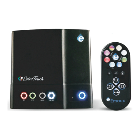
emaux COLOR TOUCH Series User manual

emaux

emaux COLOR TOUCH Series User manual

Popular Control Unit manuals by other brands

Lütze LION microPLC operating instructions

Lütze

Lütze LION microPLC operating instructions

Tech Controllers EU-L-X WiFi user manual

Tech Controllers

Tech Controllers EU-L-X WiFi user manual

RED CONNECT MODULE Operation guide

RED

RED CONNECT MODULE Operation guide

Eliwell EWRC 500 LX quick start guide

Eliwell

Eliwell EWRC 500 LX quick start guide

Becker Centronic SunWindControl SWC245-II Assembly and operating instructions

Becker

Becker Centronic SunWindControl SWC245-II Assembly and operating instructions

Allen-Bradley ControlNet 1786-RPFM installation instructions

Allen-Bradley

Allen-Bradley ControlNet 1786-RPFM installation instructions

Siemens SIPROTEC 4 7XT71 Series manual

Siemens

Siemens SIPROTEC 4 7XT71 Series manual

Pentair AURORA CBV-S/A Installation and operation manual

Pentair

Pentair AURORA CBV-S/A Installation and operation manual

National Instruments NI 9474 Getting started

National Instruments

National Instruments NI 9474 Getting started

Stahl 9482/32 Series operating instructions

Stahl

Stahl 9482/32 Series operating instructions

Comeval UNIFLOW 3P Installation, operating and maintenance manual

Comeval

Comeval UNIFLOW 3P Installation, operating and maintenance manual

KRAL BEM 500 operating instructions

KRAL

KRAL BEM 500 operating instructions

KING MP48 installation manual

KING

KING MP48 installation manual

Yoshitake OB-3 manual

Yoshitake

Yoshitake OB-3 manual

Tyco DV-5A Summary Instructions

Tyco

Tyco DV-5A Summary Instructions

Eaton ZB150 Series Instruction leaflet

Eaton

Eaton ZB150 Series Instruction leaflet

Adesys Octalarm EM-8001 quick start

Adesys

Adesys Octalarm EM-8001 quick start

urmet domus Alpha 1168 Configuration manual

urmet domus

urmet domus Alpha 1168 Configuration manual

manuals.online logo
manuals.online logoBrands
  • About & Mission
  • Contact us
  • Privacy Policy
  • Terms and Conditions

Copyright 2025 Manuals.Online. All Rights Reserved.