A) The electrician must complete preparatory steps before light fixture is installed;
see Figure 1.
I) Installing light fixture during new pool construction.
Figure 1.
1) Ensure that the pool meets the requirements of the current National Electrical Code and all local codes and
ordinances. A licensed or certified electrician must install the electrical system to meet or exceed those
requirements before the underwater light is installed. Some of the requirements of the National Electrical
Code which the Pool's electrical system must meet are as follows.
a) The lighting circuit must have a Ground Fault Circuit Interrupter (GFCI), and must have an appropriately
rated circuit breaker.
b) The Junction Box (or, for 12 volt models, the low voltage transformer) must be located at least 20CM above
water level, at least 10CM above ground level, and at least 120CM from the edge of the pool; see Figure 1.
c) The light fixture and all metal items within 152CM of the pool must be properly electrically bonded.
d) The wet niche must be properly installed so that the top edge of the underwater light's lens is at least 45.5
below the surface of the water in the pool; see Figure 1.
e) The wet niche must be properly electrically bonded and grounded via the No.8 AWG ground connector
located at the rear of the niche; see Figure 1.
NOTE: The pool or spa electrical system can be verified with a pool and Spa Electrical Qualification Test kit. The
electrical system inspection using this kit must be performed by trained and certified personnel.
2) To be certain that pool's electrical system meets all applicable requirements, the electrician should also
consult the local building department.
1) Feed cord through conduit to Junction Box, leaving at least 120CM of cord at the light fixture to coil around
the light; see Figure 1. This 120CM of cord around the light allows the light to be serviced after the pool is filled
with water.
B) Steps to perform after the electrical system requirements are met.
2-4
120CMMIN.
2.5CM RIGIDCONDUIT
#8AWGGROUND CONNECTORBONDED TOREBAR.
TOGFCI.CIRCUIT
BREAKERAND
POWERSOURCE
CONCRETEMUST BECUT BACK
AROUNDNICHE TOALLOWFOR
ACOMPACTEDPLASTER SEAL.
45.5CMMIN. FROMWATERLINE
TOTOPOF LENS
10CMMIN. 20CM MIN.JUNCTION BOXOR
LOWVOLTAGE TRANSFORMER
2) Cut the cord at the Junction BOX, leaving at least 15CM of cord to make connections.
3) Strip 15CM of the outer cord jacket to expose the three insulated wires. Be careful not to damage the
insulation on the three (3) inner wires.
4) Connect all three (3) wires to the corresponding circuit wires in the Junction Box, and secure the Junction
Box cover in place.
5) Replace the light assembly into niche and tighten special pilot screw.
6) Fill the pool until the underwater light is completely submerged in water before operating the light for more
than 10 seconds. Turn on main switch or circuit breaker, as well as the switch which operates the underwater
light itself, to check for proper operation.
Never operate this Underwater Light for more than 10 seconds unless it is totally submerged in water. Without
total submersion, the light assembly will get extremely hot, which may result in serious injury to pool users,
installers, or bystanders, or in damage to property.
Use only the special stainless steel pilot screw provided with Underwater Light. Failure to use the screw provided
could create an electrical hazard which could result in death or serious injury to pool users, installers or others
due to electrical shock.
Always disconnect power to the pool light at the circuit breaker before servicing the light. Failure to
do so could result in death or serious injury to installer, servicemen, pool users, or others due to
electrical shock.
A)Turn off main electrical switch or circuit breaker, as well as the switch which operates the underwater light
itself.
B) You will need the following items:
1) A new lens gasket.
2) A lamp, refer to Table 1 for the correct type and wattage.
Replace lamp with a similar type and wattage. Failure to replace lamp with the same type of lamp will damage the
light assembly and may cause an electrical hazard resulting in death or serious injury to pool users, installers, or others
due to electrical shock, and may also cause damage to property.
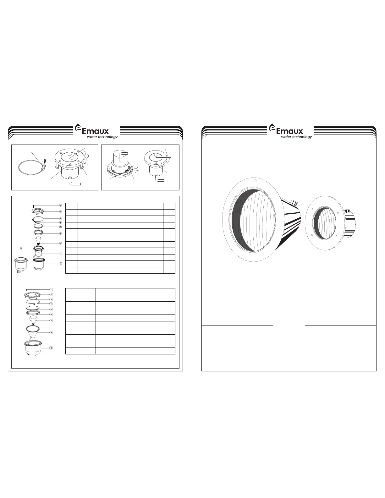
C) To remove light assembly, remove the special pilot screw at top of face ring, remove light assembly from niche,
and place assembly on deck.
D) Disassemble light fixture and remove bulb. Remove and discard old gasket.
E ) Secure the face ring to the light fixture. Sealing screws must be tightened in the following manner to ensure a
proper seal.
1) For lights with stainless face ring:
a) Partly tighten the screw at the 3 o'clock position, and then partly tighten the screw at the 9 o'clock position. Partly
tighten the screw at another 'opposite' position, and then partly tighten the screw directly across from it.
b) Continue partly tightening all screws in the above sequence until all screws are evenly and securely tightened.
Recommended 50CM pounds torque.
2) For lights with stainless steel face ring:
a) With the bent ends of the circular unitension clamp pointing down spread the clamp and place it in the "U"
recesses of the locking levers. Ensure that the bent ends of the clamp are located between the pair of locking
levers as shown in Figure 2, location A Check to see that the clamp is properly engaged with all of the levers; see
Figurer 2.
WARNING
WARNING
WARNING
3-4
II) Replacing a lamp only:
DANGER
b) Hold the ends of the unitension clamp together. Insert the bolt through one end of the bend end and then insert
the other end through the other bent end and thread the bolt into the nut. Using a #3 Phillips head screwdriver
tighten the screw and nut until the distance between the ends of the clamp equals 0.6cm or less; see Figurer 3.
G) Fill pool until the underwater light is completely submerged in water before operating the light for more than
10 seconds. Turn on main switch or circuit breaker, as well as the switch which specifically operates the
underwater light, to check for proper operation.
Use only the special pilot screw provided with this underwater light. This screw mounts and electrically grounds
the housing securely to the mounting ring and wet niche. Failure to use the screw provided could create an
electrical hazard which could result in death or serious injury to pool users, installers or others due to electrical
shock.
F) Replace the light assembly into the niche and tighten the special pilot screw.