IMPORTANT SAFETY AND INSTALLATION INSTRUCTIONS P3
1. IMPORTANT SAFETY AND INSTALLATION INSTRUCTIONS
Please read the manual carefully before commencing installation. This manual
contains important information about the correct installation and operation of TOPAZ
lights.
1. Only qualified electrician is allowed to carry out the installation of this product.
2. Avoid direct contact with electrical power.
3. Respect all regulations in effect for preventing accidents.
4. All units are required to be disconnected from the main electricity before any operation
of maintenance.
5. For safe and proper installation, ensure that those parts supplied with the produce are
used.
6. Never handle with wet hands and feet.
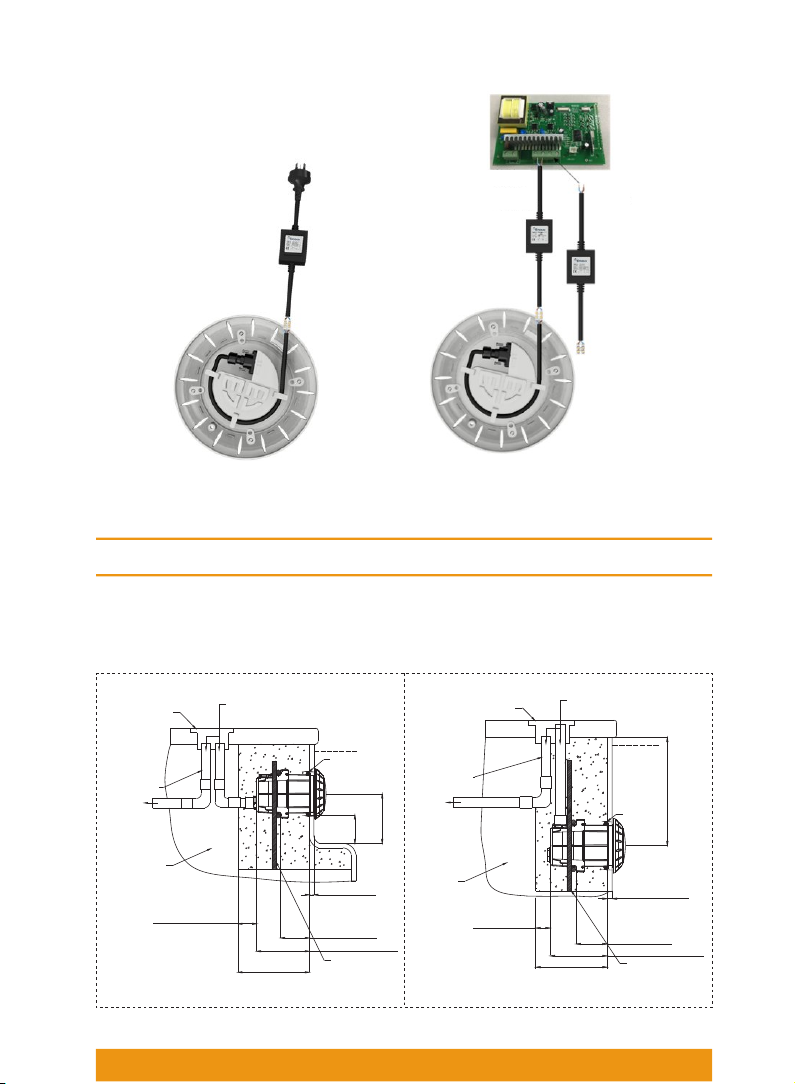
7. This unit is design for use only when fully submerged in fresh water, connecting with a
safety transformer
8. This product should be installed according to your local electrical installation ordinances
and regulations.
9. Due to the corrosive nature of unbalanced pool chemicals, please keep you pool water is
acid-base balanced prior to installation, and ensure the longevity of these lights.
10. If the external flexible cable or cord of this luminaire is damaged, it shall be exclusively
replaced by the manufacturer or his service agent or a similar qualified person in order
to avoid a hazard.
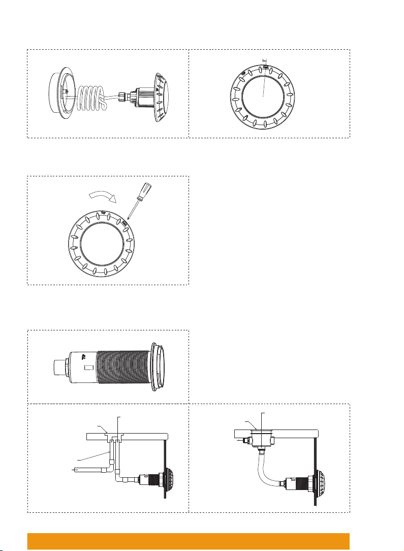
11. Check that there is enough cable behind light to allow for servicing above water,
preferably at ground-level pool-side.
12. Never operate this Underwater Light for more than 1 minute unless it is totally
submerged in water.
13. You lights require cleaning at any time, be sure to a mild detergent or other ways that
don't damage to the lights.
14. Be sure power is off before installing or removing LED plate. Allow LED plate to cool
before replacing.
15. Maximum Depth for Light installation at 1.2 meter.
16. Maximum Water Temperature Range for light operation 0-25°C
For non replacable lightsources: ”The light source of this luminaire is not replaceable; when
the light source reaches its end of life the whole luminaire shall be replaced”.
For operation only with safety isolating transformer conforming with AS/NZS 61558 series.
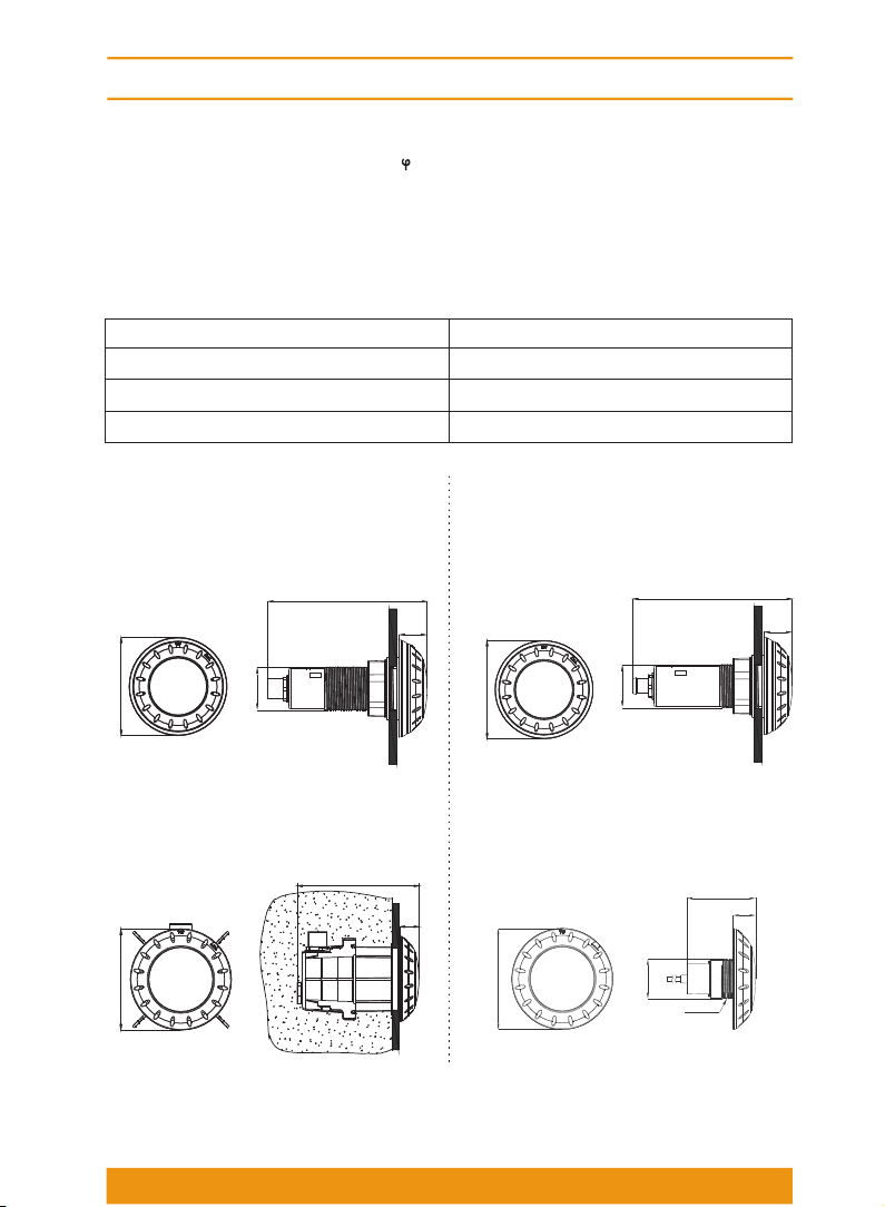
2. PRODUCT INTRODUCTION
The wall mount retrofit swimming pool underwater light is designed to latest LED lighting
technology. There are two 30 second self-determine operating mode which is fully
compatible to 50Hz or 60Hz input voltage frequency. When the lights use the same power
source, they will be self-synchronize during color change mode without color alignment
reset. The light include RGB color LED, individual warm and cool white, 5 different LED
color in total. The two mode can't be applied at the same time.