Aqua Quip AQUA-STAR User manual

1
AQUA-STAR HALOGEN LIGHTS FOR CONCRETE POOLS – INSTALLATION INSTRUCTIONS & OWNERS MANUAL
LIGHTS FOR
CONCRETE POOLS
AQUA-STAR HALOGEN
INSTALLATION INSTRUCTIONS
Included in the package are the following items:
INSTALLER – READ ENTIRE INSTRUCTION SHEET BEFORE
PROCEEDING TO INSTALL.
POOL OWNER – PLEASE KEEP THESE INSTRUCTIONS FOR
FUTURE REFERENCE.
PLEASE NOTE
THESE INSTALLATION INSTRUCTIONS APPLY TO
AQUA-STAR HALOGEN LIGHTS FOR CONCRETE POOLS ONLY.
Housing
Red
Concrete Cap Adjustable
Dress Ring
Screw
Kit
CODE DIMENSIONS (mm)
A171
B169
C120 max
D79
E63
F143
G120
H135
K Accepts 20mm conduit or
25mm socket
LAccepts 20mm socket
Aqua-Star Flush Mounted Pool Light – Concrete
Dimensions for the major components are obtained by cross-referencing the relevant code against the table.
Evo2 LED
Light
Optional Stainless Steel
Dress Ring
(not included as standard)
H
F
K
L
C
B
A
DEG
Blue and Green Lenses

AQUA-STAR HALOGEN LIGHTS FOR CONCRETE POOLS – INSTALLATION INSTRUCTIONS & OWNERS MANUAL
AQUA-STAR HALOGEN
LIGHTS FOR
CONCRETE POOLS
2
HOUSING INSTALLATION
Housing Installation – see Diagram 1
1 Aqua-Star Housing should be tied to the steel reinforcing,
before concreting the pool. A red Concrete Cap is supplied
to fit inside the front of the Housing prior to concreting.
2The Housing has two conduit connection points to
accept rigid PVC conduit, do not use flexible conduit.
Choose the appropriate provision for the situation and run
conduit above water level to form an anti-siphon loop. Top
provision accepts 20mm conduit or 25mm conduit fitting.
Rear provision accepts 20mm coupling. If using the Rear
Provision, be sure to plug the Top Provision using a 25mm
conduit cap.
3Use tie wire or cable ties through the holes on the outer
perimeter of the Housing to securely fasten it to the steel
reinforcing bars. Position the Housing so that the front will
finish level with the concrete.
4It is very important to locate Housing at a suitable location
and depth to allow for future servicing of the pool light.
Excavate sufficiently around the rear of the Housing to allow
approximately 100mm of concrete to encase it. If pool is out
of ground and fully formed, ensure the formwork allows for
concrete to encase the Housing.
5During pouring/spraying, concrete should be undercut
around the front perimeter of the Housing to allow for a
construction adhesive to be applied prior to the application
of the internal pool surface.
6Concrete should be applied to reduce the likelihood of
a void occurring on the underside of the Housing. Once
concrete has cured, construction adhesive must be applied
around the Housing to seal it to the concrete.
Diagram 1 – After Concreting
Concrete
Undercut
Alternative
Conduit
Provision
100mm
Concrete
Encasement
TECHNICAL SPECIFICATIONS AQUA-STAR HALOGEN FLUSH MOUNTED POOL LIGHTS
Nominal Supply Voltage: 12V AC 50/60 Hz
Voltage Tolerance: +2%, -10%
Protection Rating: IPX8 (to 2.0m depth)
Temperature Range: -10°C ~ +40°C water temperature
Power Consumption: 50 VA
Lamp Life: 2,000 hours
Light Output (typical): 900 Lumens
Aqua-Star Halogen Lights must only be operated underwater as they are water-cooled.
Install in an accessible location, ensure that sufficient cable is wound up inside the housing to allow the light to be
floated to the deck level. If being installed facing up, ensure that there is minimum 100mm of water cover and change
globe to max 30 watts.
Aqua-Star Halogen Pool Lights can be installed on a vertical or horizontal pool surface. Up to 1.6m of cable can be
wound up inside the Concrete Housing.

AQUA-STAR HALOGEN LIGHTS FOR CONCRETE POOLS – INSTALLATION INSTRUCTIONS & OWNERS MANUAL
AQUA-STAR HALOGEN
LIGHTS FOR
CONCRETE POOLS
AQUA-STAR HALOGEN POOL LIGHTS SPARE PARTS
CODE ITEM DESCRIPTION
ASL 050 18 HOUSING – CONCRETE
ASL 116 2 PROTECTIVE CAP FOR HOUSING (RED)
ASL 051 3 ADJUSTABLE DRESS RING
ASL 054 19 NUT O-RING
ASL 102 20 GLOBE, 12V 50W
ASL 101 21 AQUA-STAR GLOBE HOLDER KIT INCLUDES GLOBE, LAMP-
HOLDER AND O-RING
ASL 052 22 BODY, DIFFUSER & LOCK RING
ASL 070 23 BLUE LENS
ASL 071 23 GREEN LENS
ASL 074 23 CLEAR LENS
ASL 065 10 SCREW KIT (5/8” CSK)
ASL 076 26 EXTENDED DRESS RING
ASL 056 24 STAINLESS STEEL TRIM RING KIT, AQUA-STAR CONCRETE
INCLUDES BLUE AND GREEN LENSES AND 7/8” CSK SCREW KIT
HOUSING INSTALLATION
Diagram 2 – Sealing
Diagram 3 – Parts
3
DRESS RING INSTALLATION
Adjustable Dress Ring Installation –
After Concreting and Sealing (Diagram 2)
7Remove red-coloured Concrete Cap. Use pvc glue or
construction adhesive to secure the Adjustable Dress
Ring inside the Housing to your required depth and
alignment. If Housing protrudes out from the concrete,
a maximum of 20mm can be cut off from the front. If
the housing has been set back too far in the wall, then
a special extension ring (P/N ASL 076) is available. The
eyeball feature on the Adjustable Dress Ring allows
adjustment so that the Adjustable Dress Ring face can
be aligned flush with the anticipated pool interior finish
even if the Housing is out of alignment. When gluing or
securing the Adjustable Dress Ring, ensure that 2 of the
screw holes are located horizontally.
8The Cable can be drawn through, excess cable must be
coiled up and stored inside Housing.
Important: Allow enough cable to enable pool light to
be floated to pool deck.
9The Adjustable Dress Ring is now in position ready for
the pool interior to be applied. Pool interior should finish
flush with the front face of the Adjustable Dress Ring.
Adjustable
Dress Ring
Installed
and
Sealed
Interior
Pool Wall
Finish
Construction
Adhesive Seal
Concrete
AQUA-STAR HALOGEN POOL LIGHTS – PARTS
21
18
2 3 23 24
19
20 22
Nut is not sold separately
10
Extended Dress Ring (Item 26)
is required (in place of Item 3)
when front of housing is set
back more than 65mm from
intended interior pool finish.
26

AQUA-STAR HALOGEN LIGHTS FOR CONCRETE POOLS – INSTALLATION INSTRUCTIONS & OWNERS MANUAL
AQUA-STAR HALOGEN
LIGHTS FOR
CONCRETE POOLS
ELECTRICAL
CONNECTION AND
OPERATION
s
Install Light(s) and Transformer(s)
in accordance with AS/NZS
3000:2007 as amended.
s!QUA1UIPSEXTRALOWVOLTAGE
Transformers have either 2 or 4
secondary outputs, each being
12v 50VA, refer to Diagram 4.
4
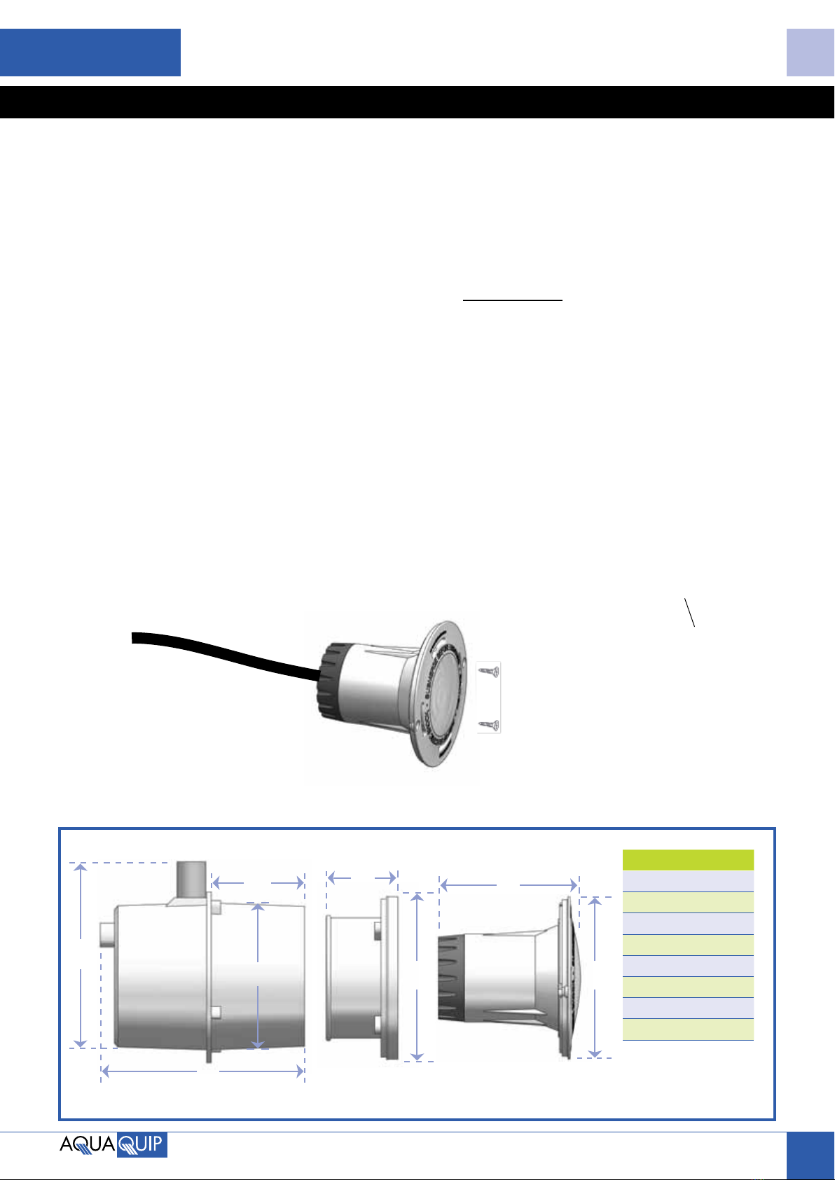
POOL LIGHT INSTALLATION
Pool Light Installation
10 Clean any debris that may have entered the
Housing and Adjustable Dress Ring during pool
construction. Insert and coil up excess cable into
the Housing. Aqua-Star Halogen self-locates onto
the Adjustable Dress Ring, use two 5/8" CSK
stainless steel screws provided to attach pool light
to Adjustable Dress Ring, do not overtighten.
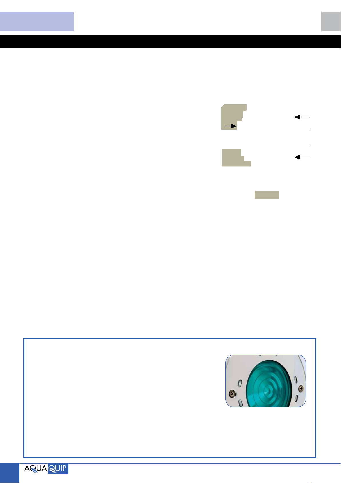
Blue and green lens covers are included, fit either
onto the light before securing light to the Adjustable
Dress Ring.
11 Fit optional Polished Stainless Steel Trim Ring if
required, using the 7/8” CSK stainless steel screws
provided in the Stainless Steel Trim Ring Kit.
12 Only turn pool light on when completely submerged
under water.
Automatic Pool Cleaners (Australia) Pty Ltd
40 Percy Street, Auburn NSW 2144
Ph: 02 9643 8338 Fax: 02 9643 8448
www.aquaquip.com.au
COPYRIGHT AUTOMATIC POOL CLEANERS (AUSTRALIA) PTY LTD ASCM4p_0112
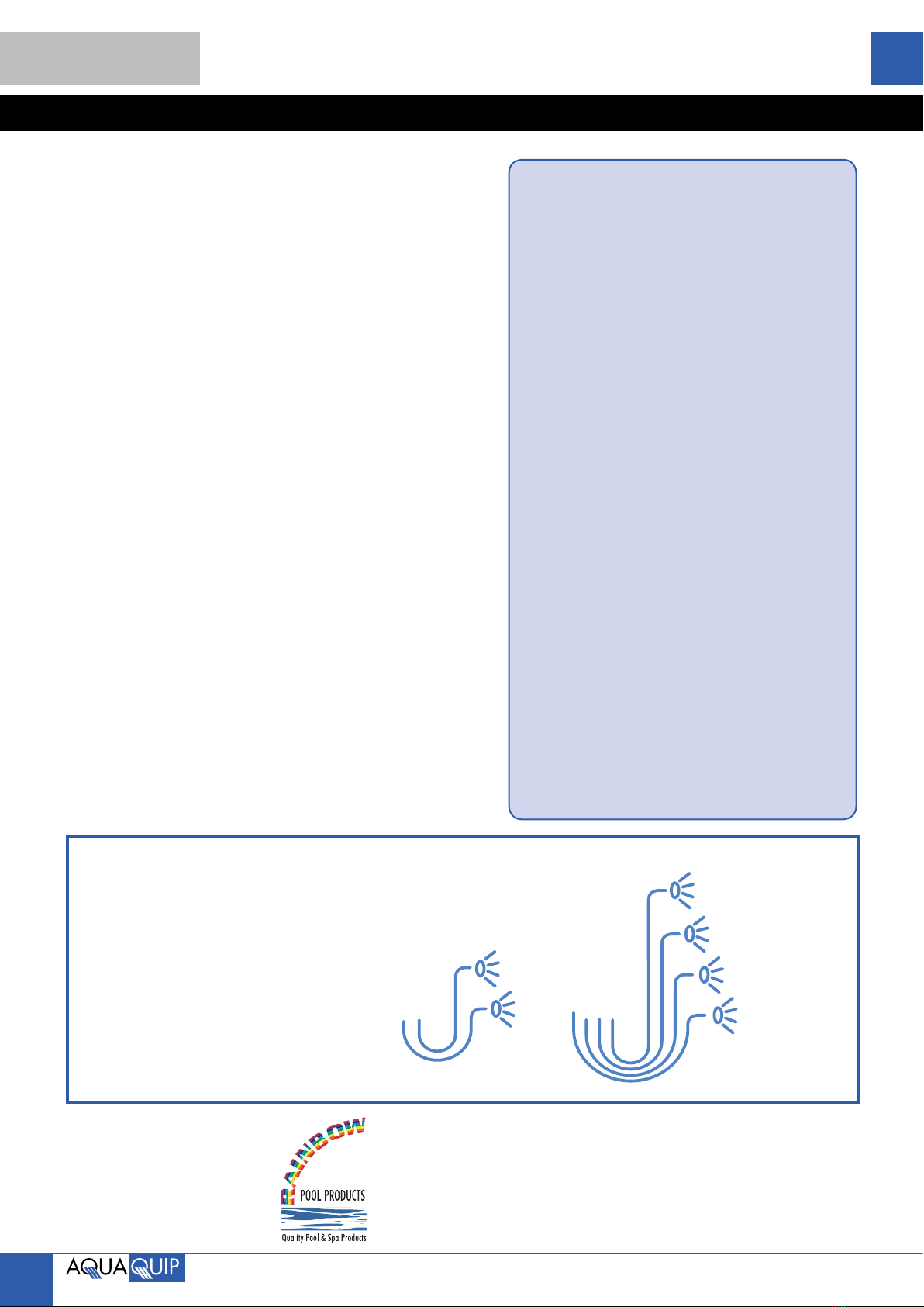
APL502 and
APL 512 run up to
2 x 50VA lights.
APL504 and APL514 run
up to 4 x 50VA lights.
Diagram 4 – Transformers
Ensure sufficient
cable length is
wound up inside the
Housing.
Diagram 3
TRANSFORMERS
AQUA-STAR GLOBE CHANGING
INSTRUCTIONS
1) Unscrew the 2 stainless steel screws, remove stainless
steel trim ring and/or coloured lens if fitted.
2) Float the light to the surface and place on deck.
3) Grip the rear black nut with multi grips or use a
screwdriver through the two holes in the black nut and
¼ turn anticlockwise whilst holding the white body of the
light. This will remove the nut from the body, exposing
the globe.
4) Remove existing globe by gently pulling the top of the
reflector, do not pull on the glass. Replace the globe
using a 12v 50w MR16 Globe, 55-60 degree beam.
Never touch the glass when replacing the globe.
5) Replace and lubricate the nut o-ring. The replacement
and lubrication of this o-ring is necessary any time the
Aqua-Star light is disassembled. Only use silicone based
lubricants.
6) If ceramic lamp holder is damaged or corroded, then it
should be removed using long nosed pliers. The male
spades of the new ceramic lamp holder will push into
the female spades. Replacement ceramic lamp holders
are available in kit form.
7) To re-insert nut into body. Place light body onto folded
towel on ground with clear diffuser facing down. Align
the mark on the nut with the alignment mark on the
body, firmly push nut into body and ¼ turn clockwise.
8) Excess cable can be loosely wrapped around the body
and/or inserted into the rear of the housing.
9) Remount the light (and coloured lens and stainless steel
trim ring if fitted) to the dress ring using the 2 stainless
screws. Fully submerge before operating.
Rainbow Pool Products
PO Box 2388, Mansfield Qld 4122
Telephone STD 61-7-3849 5385
Facsimile STD 61-7-3849 5384
Email: [email protected]
Web: www.rainbowpoolproducts.com.au
Other Aqua Quip Swimming Pool Lighting manuals
Popular Swimming Pool Lighting manuals by other brands

Astral Pool
Astral Pool LumiPlus MINI 2.0 manual

AFO
AFO Pool Starry Skies Installation details

lumz
lumz MARINO A installation manual

BEGA
BEGA 88 913 Instructions for use

Astral Pool
Astral Pool DMX Installation, operation and maintenance manual

Pentair
Pentair MAGICSTREAM LAMINAR Installation and user guide

ACIS
ACIS weltico 65035LB15 manual

Pentair Pool Products
Pentair Pool Products Pool and Spa MagicStream Laminar installation guide

Wibre
Wibre 4.0282 installation manual

Spa Electrics
Spa Electrics RETRO Series Installation & owner's manual

Intex
Intex WL3220 owner's manual

J&J Electronics
J&J Electronics PureWhite Installation and operation guide