Jandy Jandy Pro Series User manual

H0621300 Rev C
ENGLISH |FRANÇAIS | ESPAÑOL
INSTALLATION AND
OPERATION MANUAL
WARNING
FOR YOUR SAFETY - This product must be installed and serviced by a contractor who is licensed and
qualified in pool equipment by the jurisdiction in which the product will be installed where such state or
local requirements exist. The maintainer must be a professional with sufficient experience in pool equipment
installation and maintenance so that all of the instructions in this manual can be followed exactly. Before
installing this product, read and follow all warning notices and instructions that accompany this product.
Failure to follow warning notices and instructions may result in property damage, personal injury, or death.
Improper installation and/or operation will void the warranty.
Improper installation and/or operation can create unwanted electrical hazard which can
cause serious injury, property damage, or death.
ATTENTION INSTALLER - This manual contains important information about the installation,
operation and safe use of this product. This information should be given to the owner/
operator of this equipment.
Jandy Pro Series
White LED Lights
Underwater Large and Small Light

Page 2 ENGLISH Jandy®Pro Series, White LED Lights |Installation Manual
Section 1. Safety Information.......................... 3
Section 2. Product Description and Model
Numbers.......................................... 4
Section 3. Installing Jandy Light Fixture during
New Construction........................... 5
3.1 Preparing the Light Fixture for Installation.......... 5
3.2 Installing the Light Fixture ................................. 6
Section 4. Replacing Jandy Light Fixture in an
Existing Pool or Spa....................... 6
4.1 Preparing the Light Fixture for Replacement...... 6
4.2 Replacing the Light Fixture ................................ 7
Section 5. Wiring Options for Controlling Jandy
White LED Lights............................ 8
5.1 Wiring to an AquaLink®RS Control System ....... 8
5.2 Wiring to a Time Clock ....................................... 8
5.3 Wiring to a Switch............................................... 8
Table of Contents
Section 7. Replacing Light Engine (PCB)..... 10
7.1 Pool Clamp Removal........................................ 10
7.2 12V Small Light Driver (PCB) Replacement..... 10
7.3 120V Small LED Board Replacement ...............11
7.4 120V Small Light Driver (PCB) Replacement....11
7.5 Large Light Driver (PCB) Replacement
(120V and 12V) .................................................11
7.6 Reassemble the Fixture ....................................11
7.7 Reinstall the Jandy Pro Series Light into
Niche Fixture .................................................... 13
Section 8. Twelve (12) Volt Installation......... 13
Section 9. Exploded View and Replacement
Parts............................................... 14
9.1 Jandy Large White LED Light........................... 14
9.2 Jandy Small White LED Light........................... 15

Page 3
ENGLISH
Jandy®Pro Series, White LED Lights |Installation Manual
Section 1. Safety Information
IMPORTANT SAFETY INSTRUCTIONS PERTAINING TO A RISK OF FIRE,
ELECTRIC SHOCK, OR INJURY TO PERSONS
READ AND FOLLOW ALL INSTRUCTIONS
When installing and using this electrical equipment, basic safety precautions should always be followed, including the
following:
SAVE THESE INSTRUCTIONS
CAUTION
Except when the Jandy Pro Series White LED Lights are installed in an area of the swimming pool that is not used
for swimming and the lens is adequately guarded to keep any person from contacting it, the light shall be installed
in or on a wall of the pool, with the top of the lens opening not less than 18 inches (457 mm) below the normal
water level of the pool
NOTICE
The Jandy Pro Series White LED Lights are intended for installation in fresh water and salt water swimming pools.
It is important to ensure that the wet niches in which the lights are installed are intended for their appropriate
application, either fresh water or salt water pools.
WARNING
RISK OF ELECTRICAL SHOCK OR ELECTROCUTION. This underwater light must be installed by a
licensed or certified electrician in accordance with the National Electrical Code and applicable local codes and
ordinances. Improper installation will create an electrical hazard, which could result in death or serious injury to pool
or spa users, installers, or others due to electrical shock, and may also cause damage to property. Read and follow
the specific instructions below.
WARNING
Before installing this underwater light, read and follow all warning notices and instructions accompanying this light.
Failure to follow safety warnings and instructions can result in severe injury, death, or property damage. To obtain
additional copies of this manual, contact Zodiac Pool Systems, Inc at 1.800.822.7933 or visit
www.zodiacpoolsystems.com
ATTENTION INSTALLER
This manual contains important information about the installation, operation and safe use of this
product. This information should be given to the owner/operator of this equipment.

Page 4 ENGLISH Jandy®Pro Series, White LED Lights |Installation Manual
Section 2. Product Description and Model Numbers
Model # Size Color Temp. Voltage Watts Cord Length Face Ring Material
WWPLV3LS150 Large 2700 12 Volt AC 42W 150 feet Stainless Steel
WPLV3LS100 Large 5000 12 Volt AC 42W 100 feet Stainless Steel
WPLV3LS150 Large 5000 12 Volt AC 42W 150 feet Stainless Steel
WPLV3LS50 Large 5000 12 Volt AC 42W 50 feet Stainless Steel
WWPLV5LS150 Large 2700 12 Volt AC 65W 150 feet Stainless Steel
WPLV5LS100 Large 5000 12 Volt AC 65W 100 feet Stainless Steel
WPLV5LS150 Large 5000 12 Volt AC 65W 150 feet Stainless Steel
WPLV5LS50 Large 5000 12 Volt AC 65W 50 feet Stainless Steel
WWPHV3LS150 Large 2700 120 Volt AC 42W 150 feet Stainless Steel
WPHV3LS100 Large 5000 120 Volt AC 42W 100 feet Stainless Steel
WPHV3LS150 Large 5000 120 Volt AC 42W 150 feet Stainless Steel
WPHV3LS50 Large 5000 120 Volt AC 42W 50 feet Stainless Steel
WPHV5LS150 Large 5000 120 Volt AC 65W 150 feet Stainless Steel
WPHV5LS100 Large 5000 120 Volt AC 65W 100 feet Stainless Steel
WWPHV5LS150 Large 2700 120 Volt AC 65W 150 feet Stainless Steel
WPHV5LS50 Large 5000 120 Volt AC 65W 50 feet Stainless Steel
WPHV5LS250 Large 5000 120 Volt AC 65W 250 feet Stainless Steel
WWSLV1LS150 Small 2700 12 Volt AC 18W 150 feet Stainless Steel
WSLV1LS150 Small 5000 12 Volt AC 18W 150 feet Stainless Steel
WSLV1LS100 Small 5000 12 Volt AC 18W 100 feet Stainless Steel
WSLV1LS50 Small 5000 12 Volt AC 18W 50 feet Stainless Steel
WWSHV1LS150 Small 2700 120 Volt AC 18W 150 feet Stainless Steel
WSHV1LS100 Small 5000 120 Volt AC 18W 100 feet Stainless Steel
WSHV1LS150 Small 5000 120 Volt AC 18W 150 feet Stainless Steel
WSHV1LS50 Small 5000 120 Volt AC 18W 50 feet Stainless Steel
WSHV1LS250 Small 5000 120 Volt AC 18W 250 feet Stainless Steel

Page 5
ENGLISH
Jandy®Pro Series, White LED Lights |Installation Manual
Section 3. Installing Jandy
Pro Series Light
Fixture during New
Construction
WARNING
Risk of Electrical Shock or Electrocution. This
underwater light must be installed by a licensed or
certified electrician or a qualified pool serviceman in
accordance with the National Electrical Code and all
applicable local codes and ordinances
in the US, the
Canadian Electrical Code (“CEC” or C22.1) in Canada
.
Improper installation will create an electrical hazard,
which could result in death or serious injury to pool or
spa users, installers or others due to electrical shock,
and may also cause damage to property.
Always disconnect the power to the light at the
circuit breaker before installing or servicing the light.
Failure to do so could result in death or serious injury
to serviceman, pool or spa users or others due to
electrical shock.
3.1 Preparing the Light Fixture for
Installation
NOTE The electrician must complete preparatory steps
before light fixture is installed. See Figure 1.
Ensure that the pool meets the requirements of the
current National Electrical Code®and all local codes
in
the US, the Canadian Electrical Code (“CEC” or C22.1) in
Canada
. A licensed or certied electrician must install the
electrical system to meet or exceed those requirements
before the underwater light is installed. Some of the
requirements of the National Electrical Code, which the
pool electrical systems must meet, are as follows:
WARNING
To minimize risk of Electrical shock or electrocution,
which could result in injury or death, for supply
connection of low-voltage lights use only an isolating
low voltage power supply, evaluated and listed by a
Nationally Recognized Testing Laboratory (NRTL) for
swimming pool use.
1. The lighting circuit must have a Ground Fault
Circuit Interrupter (GFCI) for 120 volt models,
and must have an appropriately rated circuit
breaker.
2. The junction box (or, for 12 volt models, the low
voltage transformer) must be located at least eight
(8) inches above water level, at least four (4)
inches above ground level, and at least four (4)
feet from the edge of the pool. See Figure 1.
3. The light xture and all metal items within ve
(5) feet of the pool must be properly electrically
bonded to a reliable point of grounding.
4. The wet niche must be properly installed so that
the top edge of the underwater light’s lens is at
least 18 inches below the surface of the water in
the pool. See Figure 1.
5. The wet niche must be properly electrically
bonded and grounded via the No. 8 AWG ground
connector located at the rear of the niche. See
Figure 1.
NOTE To be certain that the pool’s electrical system meets
all applicable requirements, the electrician should also
consult the local building department.
Use only approved wet niches (see following note) to
ensure a safe and proper installation.
NOTE Jandy Pro Series lights are ETL listed (ETL report/
file 3141154CHI) for installation with only the following
manufacturer’s wet niche fixtures:
Large Niche Model Numbers:
Jandy Pro Series: PLNICLRG, PLNICVFLRG,
WT000002, SSNICLRG1R, SSNICLRG1S
Pentair: 620004, 78210200 thru 700,
78210401, 79206700
Hayward DuraNiche: SP0600U
Sta-Rite: 05161-2352 thru 2369, 05163-2395
thru 2396
Small Niche Model Numbers:
Jandy Pro Series: PLNICSM, SSNICSM,
Pentair: 78241100, 78242200, 78242300
78243100 thru 300, 78244100 thru 300,
79206600
Hayward DuraNiche: SP0601U
Sta-Rite: 05166-1017 thru 1034, 05167-1035
thru 1037
Pentair®and Sta-Rite®are registered trademarks of Pentair, Inc.
Hayward®is a registered trademark and DuraNiche™is a trademark of
Hayward Pool Products, Inc.
4" min.
48"
min.
8" min. Junction Box or Low
Voltage Transformer, to the
max water level of the pool.
18" min. to top of Lens.
11.50"
Concrete must be cut
back around Niche to
allow for a compacted
plaster seal.
Coil 4 ft. of light cable
around Fixture.
#8 AWG Ground
Connector bonding
is located at rear
of niche.
Rigid
Conduit
To GFCI, Circuit
Breaker and
Power Source.
16”
Figure 1. Jandy Pro Series LED Light Installation

Page 6 ENGLISH Jandy®Pro Series, White LED Lights |Installation Manual
3.2 Installing the Light Fixture
NOTE Perform these steps only after the electrical system
requirements are met.
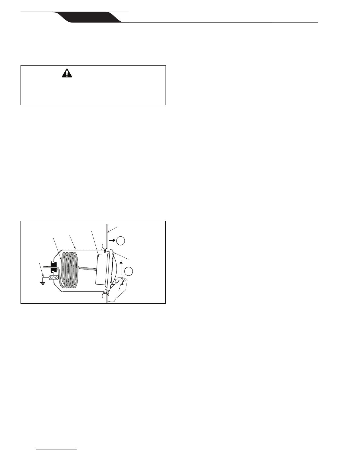
1. Feed cord through conduit to junction box,
leaving at least four (4) feet of cord at the light
xture to coil into the base of the light niche, see
Figure 1. The four (4) feet of cord allows the light
to be serviced after the pool is lled with water.
2. Cut the cord at the junction box, leaving at least
six (6) inches of cord to make connections.
3. Strip six (6) inches of the outer cord jacket to
expose the three insulated wires.
Be careful not to
damage the insulation on the three (3) inner wires.
4. Install strain relief over cord jacket and connect
all three (3) wires to the corresponding circuit
wires in the junction box. Install the junction box
cover.
5. Coil the 4-foot length of cord around the xture
or into the base of the pool niche, and place the
light assembly into the niche.
6. Engage the retainer tab on the bottom of the face
ring, then pivot the top of the xture inward and
tighten the special pilot screw.
WARNING
Use only the special pilot screw provided with this
underwater light. This screw mounts and electrically
grounds the housing securely to the mounting ring
and wet niche. Failure to use the screw provided could
create an electrical hazard, which could result in death
or serious injury to pool or spa users, installers or
others due to electrical shock.
7. Fill the pool until the underwater light is
completely submerged in water before operating
the light for more than 2 minutes. The light will
heat up quickly when operated outside of water.
Turn on main switch or circuit breaker, and the
switch, which operates the underwater light, to
check for proper operation. Refer to Section 6,
Operating Instructions.
WARNING
Never operate this underwater light for more than
10 seconds unless it is totally submerged in water.
Without total submersion, the light assembly will get
extremely hot, which may result in serious burns or in
breakage of the bulb or lens. This may result in serious
injury to pool or spa users, installers, or bystanders or
damage to property.
Section 4. Replacing Jandy Pro
Series Light Fixture in
an Existing Pool or Spa
WARNING
Risk of Electrical Shock or Electrocution. This
underwater light must be installed by a licensed or
certified electrician or a qualified pool serviceman in
accordance with the National Electrical Code and all
applicable local codes and ordinances
in the US, the
Canadian Electrical Code (“CEC” or C22.1) in Canada
.
Improper installation will create an electrical hazard,
which could result in death or serious injury to pool or
spa users, installers or others due to electrical shock,
and may also cause damage to property.
Always disconnect the power to the light at the
circuit breaker before installing or servicing the light.
Failure to do so could result in death or serious injury
to serviceman, pool or spa users or others due to
electrical shock.
4.1 Preparing the Light Fixture for
Replacement
Verify that the pool meets the requirements of the current
National Electrical Code®(NEC) and all local codes and
ordinances
in the US, the Canadian Electrical Code (“CEC”
or C22.1) in Canada
. A licensed or certied electrician
must install the electrical system to meet or exceed those
requirements before the underwater light is installed.
Some of the requirements of the National Electrical
Code, which the pool’s electrical system must meet, are
as follows:
1. The lighting circuit must have a Ground Fault
Circuit Interrupter (GFCI) for 120 volt models,
and must have an appropriately rated circuit
breaker.
2. The junction box (or, for 12 volt models, the low
voltage transformer) must be located at least eight
(8) inches above water level, at least four (4)
inches above ground level or pool deck level, and
at least 48 inches from the edge of the pool or spa.
See Figure 1.
3. The light xture and all metal items within ve
(5) feet of the pool must be properly electrically
bonded to a reliable point of grounding.
4. The wet niche must be properly installed so that
the top edge of the underwater light’s lens is at
least 18 inches below the surface of the water in
the pool. See Figure 1.

Page 7
ENGLISH
Jandy®Pro Series, White LED Lights |Installation Manual
5. The wet niche must be properly electrically
bonded and grounded via the No. 8 AWG ground
connector located at the rear of the niche. See
Figure 1.
To be certain that the pool’s electrical system meets
all applicable requirements, the electrician should also
consult the local building department.
4.2 Replacing the Light Fixture
NOTE Perform these steps only after the electrical system
requirements are met.
WARNING
Failure to bring the pool’s electrical system up to code
requirements before installing the underwater light
will create an electrical hazard which could result in
death or serious injury to pool or spa users, installers,
or others due to electrical shock, and may also cause
damage to property.
NOTE The light fixture may be replaced without removing
water from the pool.
1. Turn off the main electrical switch or circuit
breaker, as well as the switch, which operates the
underwater light.
2. Unscrew the special pilot screw at top of the
face ring and remove the light assembly from the
niche, and place the assembly on the deck.
WARNING
Be sure to keep the special pilot screw provided
with this underwater light. This screw mounts and
electrically grounds the housing securely to the
mounting ring and wet niche. Failure to use the screw
provided could create an electrical hazard, which could
result in death or serious injury to pool or spa users,
installers or others due to electrical shock.
3. Remove Junction Box cover, disconnect the light
xture wires and strain relief, and then pull the
cord out of the conduit from the niche.
4. Feed the new light xture cord through the
conduit from the niche to the Junction Box.
NOTE Depending on the length of the conduit, special tools
may be required to pull the cord through the conduit.
5. Leave at least four (4) feet of cord to coil around
the light xture or coiled into the base of the light
niche, see Figure 1. This allows the light to be
serviced after the pool is lled with water.
6. Cut the cord at the Junction Box, leaving at least
six (6) inches of cord to make connections.
7. Strip six (6) inches of the outer cord jacket from
the cord to expose the three insulated wires. Be
careful not to damage the insulation on the three
(3) inner wires.
8. Install the strain relief over the cord jacket and
connect all three wires to the corresponding
circuit wires in the junction box. Install the
junction box cover.
9. Reinstall the light assembly into the niche and
tighten the special pilot screw.
WARNING
Use only the special pilot screw provided with this
underwater light. This screw mounts and electrically
grounds the housing securely to the mounting ring
and wet niche. Failure to use the screw provided could
create an electrical hazard, which could result in death
or serious injury to pool or spa users, installers or
others due to electrical shock.
10. Fill the pool until the underwater light is
completely submerged in water before operating
the light for more than 10 seconds. Turn on main
switch or circuit breaker, as well as the switch,
which operates the underwater light, to check for
proper operation. Refer to Section 6, Operating
Instructions.
WARNING
Never operate this underwater light for more than
10 seconds unless it is totally submerged in water.
Without total submersion, the light assembly will get
extremely hot, which may result in serious burns or in
breakage of the bulb or lens. This may result in serious
injury to pool or spa users, installers, or bystanders or
in damage to property.
Section 5. Wiring Options for
Controlling Jandy
Pro Series White LED
Lights
NOTE The Jandy Pro Series White LED Lights will not
operate properly with light dimmers. Do not wire the
Jandy Pro Series Lights to any dimming circuitry.

Page 8 ENGLISH Jandy®Pro Series, White LED Lights |Installation Manual
5.1 Wiring to an AquaLink®RS Control
System
The Jandy Pro Series White LED Lights can be wired
into the Jandy Pro Series AquaLink®RS control system
to provide simplied operation of the lights. Connect the
lights to one of the auxiliary relays in the Power Center.
NOTE It is recommended to connect one light per relay so
each light can be controlled separately. However, up to
four lights can be connected on a single relay. If there
are more than four lights installed on one AquaLink RS
system, ensure there is more than one auxiliary relay
available in the Power Center.
Refer to Figures 2 and 3 to connect the Jandy Pro Series
White Lights to the Power Center.
WARNING
RISK OF ELECTRICAL SHOCK OR
ELECTROCUTION, which could result in serious
injury or death. A Ground Fault Circuit Interrupter
(GFCI) must be provided for 120 volt models. A
Ground Fault Circuit Interrupter (GFCI) for 120
Volt transformers should be used if required by the
transformer manufacturer or if required by the local
applicable code and/or Authority Having Jurisdiction
(AHJ). When a GFCI is used, the conductors on the
load side of the GFCI circuit shall not occupy conduit,
boxes, or enclosures containing other conductors
unless the additional conductors are also protected by
a GFCI. Refer to local codes for complete details.
NOTE The Jandy Pro Series White Lights are available in
120-volt and 12-volt versions. If installing a 12-volt
light, a NRTL certified 120-volt/12-volt step-down (AC)
transformer must be used. For more information about
12-volt installations, refer to Section 8 of this manual.
5.2 Wiring to a Time Clock
The Jandy Pro Series White LED Lights can be wired
into a basic time clock to automatically turn on the lights
at a predesignated time. Refer to Figure 4 to connect the
lights into the time clock.
5.3 Wiring to a Switch
The Jandy Pro Series White LED Lights can be wired
into a switch to manually turn on/off the lights. Refer to
Figure 5 to connect the lights into the switch.
GFCI
Black
White
Green
Ground
Ground
Neutral
120 VAC
Power Supply
Black
White
Green
JUNCTION
BOX
120V
LED
Light
Figure 2. 120-Volt Jandy Pro Series White LED
Light Wiring Diagram
Black
White
Green
Ground
Neutral
120 VAC
Power Supply
Black
White
Green
JUNCTION
BOX
12V
LED
Light
120V/12V
Transformer
Black
White
Green
Figure 3. 12-Volt Jandy Pro Series White LED Light
Wiring Diagram

Page 9
ENGLISH
Jandy®Pro Series, White LED Lights |Installation Manual
Clock
Motor
Ground
Ground
Neutral
Line
A12
GFCI
Black
White
Green
Black
White
Green
JUNCTION
BOX
120V
LED
Light
120 V
SUPPLY
Figure 4. Wiring the Jandy Pro Series White LED
Light to a Time Clock
Ground
Ground
Neutral
Line
120 V
Supply
GFCI
Black
White
Green
JUNCTION
BOX
Black
White
SWITCH
Black
White
Green
120V
LED
Light
Figure 5. Wiring the Jandy Pro Series White LED
Light to a Switch
Section 7. Replacing LED Board
and Driver (PCB)
WARNING
Always disconnect power to the light at the circuit
breaker before servicing the light. Failure to do so
could result in death or serious injury to installer,
serviceman, pool or spa users or others due to
electrical shock.
1. Turn off the main electrical switch or circuit
breaker, as well as the switch, which operates the
underwater light.
2. Be sure to have the following items:
• A new lens gasket.
• A light driver board. See Table 2 for specication.
WARNING
Replace light driver with the same type. Failure to
replace the light driver with the same type will damage
the light assembly and may cause an electrical hazard
resulting in death or serious injury to pool or spa users,
installers, or others due to electrical shock, and may
also cause damage to property. Be sure the power is
switched OFF before removing or installing PCB. Allow
PCB to cool before replacing.
3. To remove the light assembly, unscrew the special
pilot screw at the top of the face ring, remove
light assembly from niche and gently place
assembly on the deck. It is not necessary to drain
down the pool. See Figure 6.
Table 2. Light Specications
Jandy Pro
Series Model
Fixture
Voltage
Watts Light Driver (PCB)
Part Number
White LED
Large Light 12 VAC 65W R0802600
White LED
Large Light 120 VAC 65W R0802700
White LED
Large Light 12 VAC 42W R0802800
White LED
Large Light 120 VAC 42W R0802900
White LED
Small Light 120 VAC R0803200
White LED
Small Light 12 VAC R0803300
WARNING
Be sure to keep the special pilot screw from this
underwater light. This screw mounts and electrically
grounds the housing securely to the mounting ring
and wet niche. Failure to use the screw provided could
create an electrical hazard, which could result in death
or serious injury to pool or spa users, installers or
others due to electrical shock.
7.1 Pool Clamp Removal.
1. Loosen the Phillips head screws (six (6) for small
light, eight (8) for large light) to allow the bottom
clamp to be removed from the face ring assembly.
Do not remove the screws or the retaining rings.
The retaining rings prevent the screws from
falling free from the bottom clamp and also aid in
ease of assembly.

Page 10 ENGLISH Jandy®Pro Series, White LED Lights |Installation Manual
5. Apply thermal grease to the back of the new LED
board.
6. Place new LED board into the heat sink with the
orientation shown in Figure 7.
7. Secure the LED board with two (2) screws and
two (2) washers.
8. Plug in the board connector.
7.4 120V Small Light Driver (PCB)
Replacement
1. Disconnect power and wait 5 minutes.
2. Remove LED board as instructed in step 7.3
3. Remove 2 screws from the heat sink and remove
the heat sink.
4. Remove both quick disconnect wires from the
PCB. Note that the black wire is connected to
ACN and the White wire is connected to ACL.
5. Remove 2 metal posts from the driver board
6. Remove driver board and place new light driver
board into the xture with the orientation shown
in Figure 7.
7. Insert metal posts back on to the screw studs.
8. Plug in both quick disconnect wires, white onto
the terminal ACL of the light driver and black
onto the ACN.
9. Align heat sink to the metal posts
10. Secure the heat sink with 2 screws
11. Apply thermal grease to the back of the new LED
board.
12. Place new LED board into the heat sink with the
orientation shown in Figure 7.
13. Secure the LED board with two (2) screws and
six (6) washers.
14. Plug in the board connector.
7.5 Large Light Driver (PCB) Replacement
(120V and 12V)
1. Disconnect power and wait 5 minutes.
2. Unplug the quick disconnect terminals and the
grounding wire (green) from the light driver.
3. Remove three (3) nuts and washers.
4. Remove the LED board, light driver board and
board connector from the light xture.
5. Apply thermal grease to the back of the new LED
board.
6. Place new LED board and light driver board into
the xture with the orientation shown in Figure 8.
7. Secure the new boards with 3 washers, spilt
washers and nuts. Torque to 12 in-lbs.
8. Plug in the white quick disconnect wire onto the
terminal AC1 (TP-L) of the light driver board.
9. Plug in black quick disconnect wire onto terminal
AC2 (TP-N) of the light driver. Ensure board
connectors are connected to both boards.
2 Remove the bottom clamp, the face ring
assembly, the glass lens, and the gasket from
the xture. Remove the silicone gasket from
the lens. Refer to Section 9, Exploded View and
Replacement Parts.
WARNING
To minimize risk of damage to the light and risk of
serious injury, including loss of life, ALWAYS install a
new silicone gasket whenever disassembling the light.
7.2 12V Small Light Driver (PCB)
Replacement
1. Remove both quick disconnect wires from the
PCB. Note that the black wire is connected to
ACN (TP-2) and the White wire is connected to
ACL (TP-1).
2. Remove two (2) nuts and two (2) washers.
3. Remove the light driver from the light xture.
4. Apply thermal grease to the back of the new light
driver board.
5. Place new light driver into the xture with the
orientation shown in Figure 7.
6. Secure the light driver with one (1) washer and
one (1) nut on the right side of the light driver.
Torque to 12 in-lbs.
1
POOL WALL
Power
Cord Niche
POOL LIGHT
ASSEMBLY
PILOT SCREW
Push up on
bottom of
light assembly
2
Power
Cord Niche
SPA LIGHT
ASSEMBLY SPA WALL
1
PILOT SCREW
Push up on
bottom of
light assembly
2
Unscrew pilot screw
and pull top of light
assembly away from
spa wall
Bonding
cable
Unscrew pilot screw
and pull top of light
assembly away from
pool wall
Bonding
cable
Figure 6. Removing the Jandy Pro Series White
LED Light Assembly for Light Driver
Replacement
7. Place a washer on the other stud and place the
green ground wire terminal on the washer and
secure both with the nut. Torque to 12 in-lbs.
8. Plug in the quick disconnect wire (white) onto the
terminal ACL (TP-1) of the light engine.
9. Plug in the quick disconnect wire (black) onto
terminal ACN (TP-2) of the light engine.
7.3 120V Small LED Board Replacement
1. Disconnect power and wait 5 minutes.
2. Remove two (2) screws and six (6) washers.
3. Unplug the board connector from the light engine.
4. Remove the LED board from the heat sink. If
you are also replacing the driver board, you can
proceed now to step 7.4

Page 11
ENGLISH
Jandy®Pro Series, White LED Lights |Installation Manual
10. To secure the ground wire, place the at washer,
followed by the ground wire, followed by the split
washer, securing in place with the nut. Torque to
12 in-lbs.
7.6 Reassemble the Fixture.
1. If not already done, remove the gasket from the
glass lens and install a new gasket on the lens. On
the small light, remove the diverger from the lens.
NOTE A new lens gasket must be used each time the light is
reassembled.
WARNING
Risk of Electrical Shock or Electrocution. Always
install a new lens gasket whenever disassembling the
light. Failure to do so may permit water to leak into the
assembly, which could cause:
(a) An electrical hazard resulting in death or serious
injury to pool or spa users, installers, or others due to
electrical shock, or
(b) A malfunction of the Jandy White LED Light,
which likewise could result in serious injury to pool or
spa users, installers, or bystanders, or in damage to
property.
2. While holding the xture upright, place the glass
lens with the gasket on top of the xture. Please
note that the lens gasket is not symmetrical.
Therefore, it must be installed correctly so that
the lens can seal to the xture housing. Place the
gasket on the lens with the orientation shown in
Figure 10. On the small light, replace the diverger
by tucking the tabs between the lens and gasket.
NOTE Be sure to face the dull side of the diverger down
towards the PCB.
3. Position the lens and gasket on the xture. Place
the face ring assembly over the lens and align the
pilot screw with the small arrow mark on the face
of the lens. Note that the small arrow mark on
the face of the lens and the pilot screw of the face
ring must be aligned with the arrow located on
xture label that reads, “Arrow on this label must
line up with the pilot screw on the Face Ring”.
See Figure 9.
4. While holding the aligned face ring assembly and
xture together, turn the assembly upside down
and set it on the old gasket, using the old gasket
as an assembly xture. This will keep the lens
and gasket assembly from being pushed out of the
face ring while you secure it to the light xture.
5. Spread the bottom clamp over the electrical cord
and slide it onto the back of xture to the top
clamp.
6. Tighten the Phillips head screws (eight (8) for
large light and six (6) for small light) on the light
in alternating cross-pattern. Torque screws to
approximately 25 in-lbs.
7. Discard the old gasket.
7.7 Reinstall the Jandy Pro Series Light
Into Niche Fixture.
1. Coil the extra four (4) feet of cord around the
xture or into the base of the niche and place the
light assembly into the niche.
2. Engage the retainer tab on the bottom of the face
ring, then pivot the top of the xture inward and
tighten the special pilot screw.
WARNING
Use only the special pilot screw provided with this
underwater light. This screw mounts and electrically
grounds the housing securely to the mounting ring
and wet niche. Failure to use the screw provided could
create an electrical hazard, which could result in death
or serious injury to pool or spa users, installers or
others due to electrical shock.
3. If pool is empty, Fill the pool until the underwater
light is completely submerged in water before
operating the light for more than 2 minutes. The
light will heat up quickly when operated outside
of water. Turn on main switch or circuit breaker,
and the switch, which operates the underwater
light, to check for proper operation.
WARNING
Never operate this underwater light for more than
10 seconds unless it is totally submerged in water.
Without total submersion, the light assembly will get
extremely hot, which may result in serious burns or in
damage to the light. This may result in serious injury
to pool or spa users, installers, or bystanders or in
damage to property.
Fixture Lens
Thick molded
side of the
gasket must
mate with
the body of
the housing
Figure 10. Cross Section of Jandy Pro Series White
LED Light

Page 12 ENGLISH Jandy®Pro Series, White LED Lights |Installation Manual
Section 8. Twelve (12) Volt
Installation
A separate 12-Volt AC Transformer is required on all
12-Volt Models. For Jandy Pro Series White LED Light
use a 150-watt multi-tap 12-volt system per light.
WARNING
RISK OF ELECTRICAL SHOCK OR
ELECTROCUTION, which could result in serious
injury or death. for supply connection of low-voltage
lights use only an isolating low voltage power supply
with ungrounded output, evaluated and listed by a
NRTL for swimming pool use.
NOTE For optimum performance Jandy Pro Series
recommends to use one transformer per 12-volt light.
To ensure maximum safety, it is strongly recommended
that a transformer that has been listed or recognized by
a Nationally Recognized Testing Laboratory (NRTL) for
the application be used.
Green
ACN (Black)
ACL (White)
LED Board
Connector
LED Board
Connector
Serrated
Washer
Split
Washer
Nut
White (12V)
White (120V)
TP-1 (White)
TP-1
AC1
White
Black (12V)
Black (120V)
TP-2 (Black)
TP-2
AC2
Black
120V Wiring LED Board 120V Wiring Driver Board
12V Wiring LED Board
Green
Nut
White (12V)
TP-1 (White)
TP-1
AC1
White
Black (12V)
TP-2 (Black)
TP-2
AC2
Black
12V/120V Wiring
Serrated
Washer
Split
Washer
Figure 8. Large Light Engine (PCB) Replacement
and Wiring
Figure 9. Alignment of the Lens, Face Ring, Housing
and Clamps for White LED Lights
Figure 7. Small Light Engine (PCB) Replacement and Wiring
Align arrow of the
lens with the pilot
screw
Align pilot screw with
the arrow located on
the xture label

Page 13
ENGLISH
Jandy®Pro Series, White LED Lights |Installation Manual
Section 9. Exploded View and Replacement Parts
9.1 Jandy Pro Series Large White LED Light
1
8
5
2
35 467 7
1
8
5
2
35 467 7
Figure 11. Jandy Pro Series Large White LED Light Exploded View
DWG # Part # Description Field Replaceable
1 N/A White LED Light Housing NO - Purchase New Light
2 R0802600 Light Engine PCB, 12V, 5K, 65W Large LED YES
2 R0802601 Light Engine PCB, 12V, 2.7K 65W Large LED YES
2 R0802700 Light Engine PCB, 120V, 5K, 65W Large LED YES
2 R0802701 Light Engine PCB, 120V, 2.7K, 65W Large LED YES
2 R0802800 Light Engine PCB, 12V, 5K, 42W Large LED YES
2 R0802801 Light Engine PCB, 12V, 2.7K, 42W Large LED YES
2 R0802900 Light Engine PCB, 120V, 5K, 42W Large LED YES
2 R0802901 Light Engine PCB, 120V, 2.7K, 42W Large LED YES
3 R0790500 Silicone Gasket YES
4 R0790600 Glass Lens YES
5 R0790700 Clamp Assembly YES
6 R0790801 Face Ring, Stainless Steel (SS) YES
6 R0790802 Face Ring, Plastic, White YES
6 R0790803 Face Ring, Plastic, Black YES
6 R0790804 Face Ring, Plastic, Gray YES
6 R0790805 Face Ring, Plastic Set YES
7 R0790900 Pilot Screw, with Retainer YES
8 R0791000 Clamp Screws (8 Screws and 8 Retainers) YES

Page 14 ENGLISH Jandy®Pro Series, White LED Lights |Installation Manual
9.2 Jandy Pro Series Small White LED 12V Light
1 2
3
5
467
9
1
4 2
3
6
7
7
9
7
5
8
8
8
8
1
4 2
3
6
79
7
5
8 8
Figure 12. Jandy Pro Series Small White 12V LED Light Exploded View
DWG # Part # Description Field Replaceable
1 N/A White LED Light Housing NO - Purchase New Light
2 R0803300 Light Engine, Small LED Light, 12V YES
3 R0739700 Diverger, Light Shaping, Small LED Light YES
4 R0791100 Silicone Gasket YES
5 R0791200 Glass Lens YES
6 R0791300 Clamp Assembly YES
7 R0791401 Face Ring, Stainless Steel (SS) YES
7 R0791402 Face Ring, Plastic, White YES
7 R0791403 Face Ring, Plastic, Black YES
7 R0791404 Face Ring, Plastic, Gray YES
7 R0791405 Face Ring, Plastic Set YES
8 R0790900 Pilot Screw, with Retainer YES
9 R0791600 Clamp Screws (6 Screws and 6 Retainers) YES

Page 15
ENGLISH
Jandy®Pro Series, White LED Lights |Installation Manual
9.3 Jandy Pro Series Small White 120V LED Light
1 2
3
5
467
9
1
4 2
3
6
7
7
9
7
5
8
8
8
8
1
4 2
3
6
79
7
5
8 8
Figure 13. Jandy Pro Series Small White 120V LED Light Exploded View
DWG # Part # Description Field Replaceable
1 N/A White LED Light Housing NO - Purchase New Light
2 R0803200 Light Engine, Small LED Light, 120V YES
3 R0739700 Diverger, Light Shaping, Small LED Light YES
4 R0791100 Silicone Gasket YES
5 R0791200 Glass Lens YES
6 R0791300 Clamp Assembly YES
7 R0791401 Face Ring, Stainless Steel (SS) YES
7 R0791402 Face Ring, Plastic, White YES
7 R0791403 Face Ring, Plastic, Black YES
7 R0791404 Face Ring, Plastic, Gray YES
7 R0791405 Face Ring, Plastic Set YES
8 R0790900 Pilot Screw, with Retainer YES
9 R0791600 Clamp Screws (6 Screws and 6 Retainers) YES

Zodiac Pool Systems LLC
2620 Commerce Way, Vista, CA 92081
1.800.822.7933 | www.ZodiacPoolSystems.com
Zodiac Pool Systems Canada, Inc.
2-3365 Mainway, Burlington, ON L7M 1A6
1-888-647-4004 | www.ZodiacPoolSystems.ca
ZODIAC®is a registered trademark of Zodiac International, S.A.S.U., used under license.
All trademarks referenced herein are the property of their respective owners.
©2018 Zodiac Pool Systems, Inc. H0621300 Rev C

H0621300 Rév C
FRANÇAIS
MANUEL D'INSTALLATION
ET DE FONCTIONNEMENT
AVERTISSEMENT
POUR VOTRE SÉCURITÉ, ce produit doit être installé et entretenu par un entrepreneur disposant d'une
licence et qui est qualifié en équipements de piscine par la juridiction dans laquelle le produit est installé
lorsque de telles exigences étatiques ou locales existent. L'agent d'entretien doit être un professionnel
disposant de suffisamment d'expérience dans l'installation et l'entretien des équipements de piscine afin de
s'assurer que toutes les directives du présent manuel sont scrupuleusement respectées. Avant d'installer
ce produit, lire et suivre tous les avertissements et toutes les directives qui accompagnent ce produit. Dans
le cas contraire, des dommages matériels ou des blessures, possiblement mortelles, peuvent survenir. Une
mauvaise installation et/ou un mauvais fonctionnement annulent la garantie.
Une mauvaise installation et/ou un mauvais fonctionnement peuvent engendrer un danger
électrique pouvant entraîner des dommages matériels ou des blessures graves, voire
mortelles.
À L'ATTENTION DE L'INSTALLATEUR - Ce manuel contient des informations importantes sur
l'installation, le fonctionnement et l'utilisation sécuritaire de ce produit. Ces informations
doivent être communiquées au propriétaire ou à l'exploitant de cet équipement.
Série Jandy Pro
Éclairage DEL blanche
Grand et petit éclairage subaquatique

Page 18 FRANÇAIS Série Jandy®Pro, éclairage DEL blanches |Manuel d'installation
Section 1.
Informations relatives à la sécurité
... 3
Section 2. Description du produit et
numéros de modèle........................ 4
Section 3. Installation du luminaire série Pro
de Jandy dans une construction
neuve ............................................... 5
3.1 Préparation du luminaire pour l'installation......... 5
3.2 Installation du luminaire ..................................... 6
Section 4. Remplacement du luminaire série
Pro de Jandy dans une piscine ou
un spa existant ............................... 6
4.1 Préparation du luminaire pour le remplacement.... 6
4.2 Remplacement du luminaire .............................. 7
Section 5. Options de câblage pour contrôler
l'éclairage à DEL blanches de la
série Pro de Jandy.......................... 7
5.1 Câblage à un système de contrôle
AquaLink®RS..................................................... 8
5.2 Branchement à une horloge ............................... 8
5.3 Câblage à un commutateur ................................ 8
Table des matières
Section 7. Remplacement du tableau DEL et
pilote (carte de circuit imprimé).... 9
7.1 Dépose crampon de piscine............................... 9
7.2 Remplacement de la carte de circuit imprimé
du petit luminaire 12 V...................................... 10
7.3 Remplacement de la carte du petit luminaire
120 V ................................................................ 10
7.4 Remplacement de la carte de circuit imprimé
du petit luminaire 120 V.................................... 10
7.5 Remplacement de la carte de circuit imprimé
du grand luminaire (120 V et 12 V) .................. 10
7.6 Remontage du luminaire. .................................11
7.7 Réinstaller le luminaire série Pro de Jandy
dans la niche. ....................................................11
Section 8. Installation douze (12) volts ........ 12
Section 9.
Vue éclatée et pièces de rechange
... 13
9.1 Grand luminaire à DEL blanche série
Pro de Jandy .................................................... 13
9.2 Petit luminaire à DEL 12 V blanc série
Pro de Jandy .................................................... 14
9.3 Petit luminaire à DEL blanches 120 V série
Pro de Jandy .................................................... 15

Page 19
FRANÇAIS
Série Jandy®Pro, éclairage DEL blanches |Manuel d'installation
Section 1. Informations relatives à la sécurité
IMPORTANTES CONSIGNES DE SÉCURITÉ RELATIVES AUX RISQUES
D'INCENDIE, D'ÉLECTROCHOCS OU BLESSURES CORPORELLES
LIRE ET SUIVRE TOUTES LES DIRECTIVES
Lors de l'installation et de l'utilisation de cet équipement électrique, les précautions de sécurité élémentaire doivent
toujours être respectées, notamment :
CONSERVER CES DIRECTIVES
ATTENTION
Sauf lorsque le luminaire à DEL blanches série Pro de Jandy est installé dans une zone de piscine qui n'est pas
utilisée pour nager, et que la lentille est bien protégée de manière à ne pas pouvoir être touchée, le luminaire
sera installé dans ou sur une paroi de la piscine avec le dessus de l'ouverture de la lentille à au moins 457 mm
(18 pouces) sous le niveau d'eau normal de la piscine
AVIS
Les luminaires à DEL blanches de la série Pro de Jandy sont destinés à une installation dans les piscine à eau
douce et salée. Il est important de s'assurer que les niches humides dans lesquelles sont installés les luminaires
sont destinées à une telle application, soit des piscines avec eau douce ou salée.
AVERTISSEMENT
RISQUE DE CHOC ÉLECTRIQUE OU D'ÉLECTROCUTION. Le luminaire subaquatique doit être installé par
un électricien licencié ou agréé conformément aux code national de l'électricité ainsi que les codes et ordonnances
locales en vigueur. Une mauvaise installation va créer un risque électrique, pouvant entraîner la mort ou des
blessures graves aux usagers de la piscine ou du spa, aux installateurs ou autres en raison d'un choc électrique, et
peut aussi causer un dommage matériel. Lire et suivre les directives spécifiques ci-dessous.
AVERTISSEMENT
Avant d'installer ce luminaire subaquatique, lire et suivre tous les avertissements et toutes les directives qui
l'accompagnent. Le défaut de suivre les avertissements et les directives peut entraîner de blessures graves, la mort
ou des dommages matériaux. Pour obtenir des exemplaires de ce manuel, veuillez contacter Zodiac Pool Systems,
Inc au 1.800.822.7933 ou visitez www.zodiacpoolsystems.com
À L'ATTENTION DE L'INSTALLATEUR
Ce manuel contient d'importantes informations sur l'installation, le fonctionnement et l'utilisation
sécuritaires de ce produit. Ces informations doivent être communiquées au propriétaire ou
à l'exploitant de cet équipement.

Page 20 FRANÇAIS Série Jandy®Pro, éclairage DEL blanches |Manuel d'installation
Section 2. Description du produit et numéros de modèle
N° de modèle Dimension Couleur Temp. Tension Watts Longueur de
cordon
Matériel bague de
garniture
WWPLV3LS150 Grand 2 700 12 volts c.a. 42 W 150 pieds Acier inoxydable
WPLV3LS100 Grand 5 000 12 volts c.a. 42 W 100 pieds Acier inoxydable
WPLV3LS150 Grand 5 000 12 volts c.a. 42 W 150 pieds Acier inoxydable
WPLV3LS50 Grand 5 000 12 volts c.a. 42 W 50 pieds Acier inoxydable
WWPLV5LS150 Grand 2 700 12 volts c.a. 65 W 150 pieds Acier inoxydable
WPLV5LS100 Grand 5 000 12 volts c.a. 65 W 100 pieds Acier inoxydable
WPLV5LS150 Grand 5 000 12 volts c.a. 65 W 150 pieds Acier inoxydable
WPLV5LS50 Grand 5 000 12 volts c.a. 65 W 50 pieds Acier inoxydable
WWPHV3LS150 Grand 2 700 120 volts c.a. 42 W 150 pieds Acier inoxydable
WPHV3LS100 Grand 5 000 120 volts c.a. 42 W 100 pieds Acier inoxydable
WPHV3LS150 Grand 5 000 120 volts c.a. 42 W 150 pieds Acier inoxydable
WPHV3LS50 Grand 5 000 120 volts c.a. 42 W 50 pieds Acier inoxydable
WPHV5LS150 Grand 5 000 120 volts c.a. 65 W 150 pieds Acier inoxydable
WPHV5LS100 Grand 5 000 120 volts c.a. 65 W 100 pieds Acier inoxydable
WWPHV5LS150 Grand 2 700 120 volts c.a. 65 W 150 pieds Acier inoxydable
WPHV5LS50 Grand 5 000 120 volts c.a. 65 W 50 pieds Acier inoxydable
WPHV5LS250 Grand 5 000 120 volts c.a. 65 W 250 pieds Acier inoxydable
WWSLV1LS150 Petit 2 700 12 volts c.a. 18 W 150 pieds Acier inoxydable
WSLV1LS150 Petit 5 000 12 volts c.a. 18 W 150 pieds Acier inoxydable
WSLV1LS100 Petit 5 000 12 volts c.a. 18 W 100 pieds Acier inoxydable
WSLV1LS50 Petit 5 000 12 volts c.a. 18 W 50 pieds Acier inoxydable
WWSHV1LS150 Petit 2 700 120 volts c.a. 18 W 150 pieds Acier inoxydable
WSHV1LS100 Petit 5 000 120 volts c.a. 18 W 100 pieds Acier inoxydable
WSHV1LS150 Petit 5 000 120 volts c.a. 18 W 150 pieds Acier inoxydable
WSHV1LS50 Petit 5 000 120 volts c.a. 18 W 50 pieds Acier inoxydable
WSHV1LS250 Petit 5 000 120 volts c.a. 18 W 250 pieds Acier inoxydable
Other manuals for Jandy Pro Series
8
This manual suits for next models
26
Table of contents
Languages:
Other Jandy Swimming Pool Lighting manuals
Popular Swimming Pool Lighting manuals by other brands

Astral Pool
Astral Pool 21626 Installation and maintenance manual

Pentair Pool Products
Pentair Pool Products SpaBrite Installation procedures

Aqua Quip
Aqua Quip QC Series Installation instructions & owner's manual

Spectravision
Spectravision Adagio Pro Series owner's manual

Seamaid
Seamaid LEDINPOOL 502877 Usage & Maintenance Manual