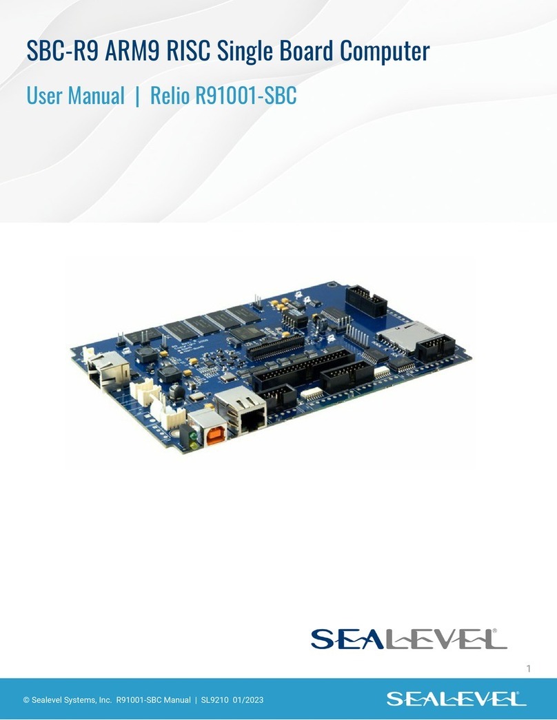
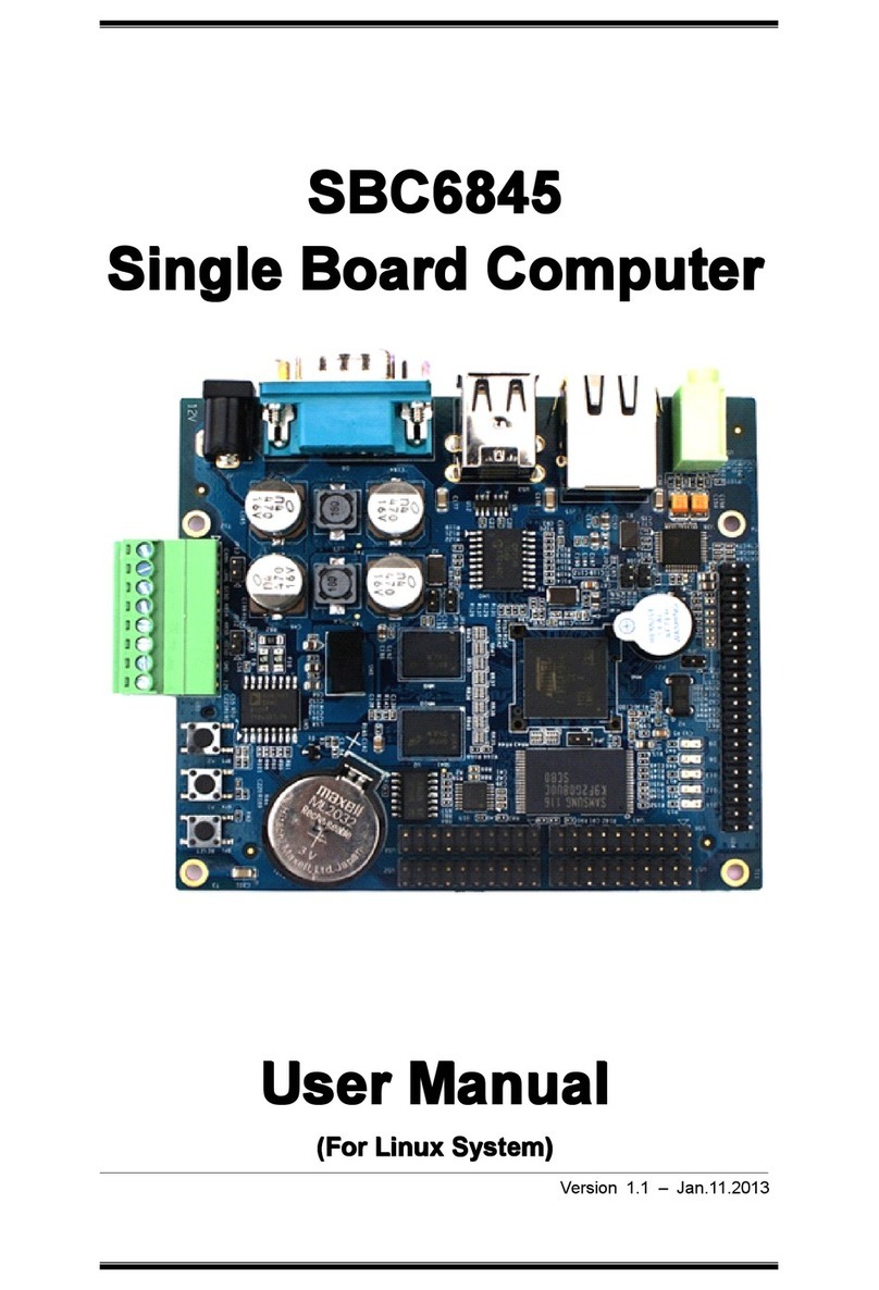
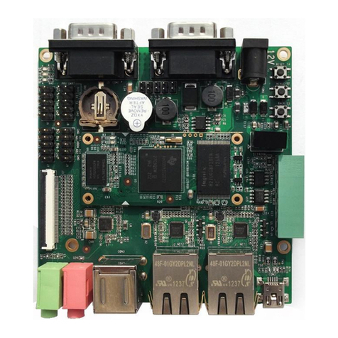
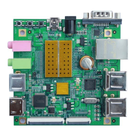
Embest SBC6045 User manual

SBC6
SBC6
SBC6
SBC6 0
0
0
0 45
45
45
45 User
User
User
User Manual
Manual
Manual
Manual
SBC6045
User
User
User
User Manual
Manual
Manual
Manual Rev.
Rev.
Rev.
Rev. 1.
1.
1.
1. 2
2
2
2
1
1
1
1 of
of
of
of 92
92
92
92
SBC6045
SBC6045
SBC6045
SBC6045 User
User
User
User Manual
Manual
Manual
Manual
Rev. 1. 2
Release: 201 3 -0 2 - 26

SBC6
SBC6
SBC6
SBC6 0
0
0
0 45
45
45
45 User
User
User
User Manual
Manual
Manual
Manual
SBC6045
User
User
User
User Manual
Manual
Manual
Manual Rev.
Rev.
Rev.
Rev. 1.
1.
1.
1. 2
2
2
2
2
2
2
2 of
of
of
of 92
92
92
92
Thank you for purchasing our products, we will do
better because of you.
Embest
Embest
Embest
Embest Info&Tech
Info&Tech
Info&Tech
Info&Tech Co.,
Co.,
Co.,
Co., LTD.
LTD.
LTD.
LTD.
Room 509 , Luohu Science&Technology Building,
#85 Taining Rd., Shenzhen, Guangdong, China 518020
Tel: +86-755-256356 56/2563 6285
Fax: + 86-755-25616057
Email: [email protected]
http://www.embedinfo.com /english
http://www.armkits.com

SBC6
SBC6
SBC6
SBC6 0
0
0
0 45
45
45
45 User
User
User
User Manual
Manual
Manual
Manual
SBC6045
User
User
User
User Manual
Manual
Manual
Manual Rev.
Rev.
Rev.
Rev. 1.
1.
1.
1. 2
2
2
2
3
3
3
3 of
of
of
of 92
92
92
92
Re
Re
Re
Re vision
vision
vision
vision record
record
record
record
Date
Date
Date
Date Revision
Revision
Revision
Revision Version
Version
Version
Version CR
CR
CR
CR ID/Defect
ID/Defect
ID/Defect
ID/Defect ID
ID
ID
ID Section
Section
Section
Section
Number
Number
Number
Number
Change
Change
Change
Change
Description
Description
Description
Description
Author
Author
Author
Author
201 1 - 05 - 27 1.0
201 1 - 08 - 02 1.1
Copyright: Embest Info&Tech Co., Ltd..Reserves the right to interpret
Non-written permission by the Company, any units and personality will be allowed to extract and
copy all or part of this document does not in any form of communication.
Attention
As the product version upgrades or other reasons, the contents of this document will be updated
from time to time. Unless otherwise agreed, the use of this document only as a guide, all
statements in this document, information and suggestions do not constitute any express or
implied.

SBC6
SBC6
SBC6
SBC6 0
0
0
0 45
45
45
45 User
User
User
User Manual
Manual
Manual
Manual
SBC6045
User
User
User
User Manual
Manual
Manual
Manual Rev.
Rev.
Rev.
Rev. 1.
1.
1.
1. 2
2
2
2
4
4
4
4
of
of
of
of
92
92
92
92
T able of C ontents
SBC6045
SBC6045
SBC6045
SBC6045 USER
USER
USER
USER MANUAL
MANUAL
MANUAL
MANUAL ...........................................................................................................
...........................................................................................................
...........................................................................................................
........................................................................................................... 1
1
1
1
PART
PART
PART
PART 1
1
1
1 OVERVIEW
OVERVIEW
OVERVIEW
OVERVIEW ...............................................................................................................
...............................................................................................................
...............................................................................................................
............................................................................................................... 6
6
6
6
CHAPTER 1 S YSTEM OVERVIEW ................................................................................................................... 6
PART
PART
PART
PART 2
2
2
2 HARDWARE
HARDWARE
HARDWARE
HARDWARE SYSTEM
SYSTEM
SYSTEM
SYSTEM .............................................................................................
.............................................................................................
.............................................................................................
............................................................................................. 7
7
7
7
CHAPTER 2 S PECIFICA TIONS OF HARDW ARE ................................................................................................. 7
2.1 CPU ......................................................................................................................................................... 7
2.2 Core board functions ............................................................................................................................... 8
2.3 Functional interfaces of main board ....................................................................................................... 8
CHAPTER 3 D ESCRIPTION OF INTERFACES ................................................................................................... 11
3.1 LAYOUT ................................................................................................................................................
11
3.2 POWER (J1 )...................................................................................................................................... 12
3.3 SDHC (SD/MMC )............................................................................................................................. 12
3.4 NET (J15) .............................................................................................................................................. 13
3.5 UART ..................................................................................................................................................... 13
3.6 BUZZER (BUZZ ).............................................................................................................................. 16
3.7 USB OTG (J11 )................................................................................................................................. 16
3.8 USB HOST (CN1 )............................................................................................................................. 16
3.9 TWI (J15 ).......................................................................................................................................... 16
3.10 AUDIO OUT (J9 )............................................................................................................................ 17
3.11 JTAG (J10 )...................................................................................................................................... 17
3.12 LCD (J20 )....................................................................................................................................... 17
3.13 KEY (B1 )......................................................................................................................................... 19
3.14 TOUCH (J20 ).................................................................................................................................. 19
3.15 LVDS (J3 )........................................................................................................................................ 19
3.16 LED (D20 )...................................................................................................................................... 21
3.17 CAN (J26 )....................................................................................................................................... 21
3.18 SPI (J31 )......................................................................................................................................... 21
3.19 POWER OUT (J28) ............................................................................................................................. 22
3.20 RTC ..................................................................................................................................................... 22
CHAPTER 4 S YSTEM ELECTRICAL DESCRIPTION ......................................................................................... 22
PART
PART
PART
PART 3
3
3
3 LINUX
LINUX
LINUX
LINUX SYSTEM
SYSTEM
SYSTEM
SYSTEM ......................................................................................................
......................................................................................................
......................................................................................................
...................................................................................................... 25
25
25
25
CHAPTER 5 O VERVIEW OF LINUX SYSTEM .................................................................................................. 25
CHAPTER 6 G ETTING S
TART
WITH SBC6045 .............................................................................................. 26
6.1 Getting Start from Nandflash ................................................................................................................ 26
6.2 Setting the type of LCD Screen .............................................................................................................. 26
CHAPTER 7 T EST TUTORIALS OF THE SBC6045 ......................................................................................... 26
7.1 Touch Screen Test .................................................................................................................................. 26
7.2 Net Test .................................................................................................................................................. 27
7.3 UART Test .............................................................................................................................................. 27
7.4 CAN Bus Test ......................................................................................................................................... 27

SBC6
SBC6
SBC6
SBC6 0
0
0
0 45
45
45
45 User
User
User
User Manual
Manual
Manual
Manual
SBC6045
User
User
User
User Manual
Manual
Manual
Manual Rev.
Rev.
Rev.
Rev. 1.
1.
1.
1. 2
2
2
2
5
5
5
5
of
of
of
of
92
92
92
92
7.5 RS-485 Test ............................................................................................................................................ 28
7.6 USB Host Test ........................................................................................................................................ 28
7.7 RTC Test ................................................................................................................................................ 29
7.8 EEPROM Test ........................................................................................................................................ 29
7.9 SD Card Test .......................................................................................................................................... 29
7.10 LED Test .............................................................................................................................................. 30
7.11 Beep Test .............................................................................................................................................. 30
CHAPTER 8 S ETTING THE DEVELOPMENT ENVIRONMENT .......................................................................... 30
8.1 Install the Cross Compiler ..................................................................................................................... 30
8.2 Setting the Cross-compiler Environment ............................................................................................... 31
8.3 Compiler the System of the SBC6045 .................................................................................................... 31
8.4 System Customization ............................................................................................................................ 32
CHAPTER 9 U PDA TE THE SYSTEM IMAGE ................................................................................................... 33
9.1 System Image Map ................................................................................................................................ 33
9.2 Setting the Environment of Burning Image ........................................................................................... 34
9.3 Burning System Image ........................................................................................................................... 34
CHAPTER 10 QT D EMO ............................................................................................................................... 47
PART
PART
PART
PART 4
4
4
4 WINCE6.0
WINCE6.0
WINCE6.0
WINCE6.0 SYSTEM
SYSTEM
SYSTEM
SYSTEM ................................................................................................
................................................................................................
................................................................................................
................................................................................................ 49
49
49
49
CHAPTER 11 I NTRODUCTION OF WIN CE6.0 S YSTEM ................................................................................. 49
11.1 Image files related to SBC6045 WinCE 6.0 system ............................................................................. 49
11.2 SBC6045 WinCE 6.0 Software List ...................................................................................................... 49
11.3 Principle of SBC6045 WinCE 6.0 ........................................................................................................ 50
11.4 Principles on the booting of SBC6045 WinCE 6.0 system ................................................................... 50
CHAPTER 12 B URNING OF WIN CE SYSTEM ................................................................................................ 52
12.1 Introduction of burning Image of SBC6045 WinCE 6.0 ...................................................................... 52
12.2 Burn SBC6045 WinCE 6.0 image through SAM-BA ........................................................................... 52
12.3 Burn WinCE 6.0 NK image files through TFTP server software CEDownload.exe ............................ 61
CHAPTER 13 C USTOMIZATION OF WIN CE SYSTEM BASED ON SBC6045 W IN CE 6.0 BSP ........................ 66
13.1 Installation of SBC6045 WinCE 6.0 BSP ............................................................................................ 66
13.2 Modules of SBC6045 WinCE 6.0 BSP ................................................................................................. 66
13.3 Compilation of WinCE system based on SBC6045 WinCE 6.0 BSP .................................................... 68
13.4 Compilation of WinCE system based on SBC6045 WinCE 6.0 BSP .................................................... 68
13.5 Modules of SBC6045 WinCE 6.0 BSP driver ...................................................................................... 78
13.6 How to enter EBOOT menu ................................................................................................................. 81
13.7 EBOOT menu commands .................................................................................................................... 83
TECHNICAL
TECHNICAL
TECHNICAL
TECHNICAL SUPPORT
SUPPORT
SUPPORT
SUPPORT AND
AND
AND
AND WARRANTY
WARRANTY
WARRANTY
WARRANTY SERVICE
SERVICE
SERVICE
SERVICE .......................................................
.......................................................
.......................................................
....................................................... 90
90
90
90
TECHNICAL SUPPORT SERVICE : ......................................................................................................................... 90
MAINTENANCE SERVICE CLAUSE : .................................................................................................................... 90
BASE NOTICE TO PROTECT AND MAINTENANCE LCD: ..................................................................................... 91
V
ALUE ADDED SERVICES : ................................................................................................................................ 91

SBC6
SBC6
SBC6
SBC6 0
0
0
0 45
45
45
45 User
User
User
User Manual
Manual
Manual
Manual
SBC6045
User
User
User
User Manual
Manual
Manual
Manual Rev.
Rev.
Rev.
Rev. 1.
1.
1.
1. 2
2
2
2
6
6
6
6
of
of
of
of
92
92
92
92
Part
Part
Part
Part 1
1
1
1 Overview
Overview
Overview
Overview
C
C
C
C hapter
hapter
hapter
hapter 1
1
1
1 System
System
System
System Overview
Overview
Overview
Overview
Embest SBC6045 is a high-performance ARM embedded single board computer (SBC) provided
versatile communication interfaces to meet a wide variety of applications such as industrial control,
automation, equipment monitoring, data logging, medical equipment, embedded web server etc. It is
based on the 400MHz Atmel AT91SAM9G45 microprocessor and features wide input range from 12V
to 36V with isolated power.
The SBC6045 board uses Mini6045 processor card as the CPU core board which has 256MB
(2*128MByte) DDR2 SDRAM, 256MB Nand Flash, 4MB Data Flash, 2Kbit EEPROM and integrates
UART, Ethernet, USB OTG, LCD, Touch screen, RTC and TF card slot on board. It connects to the
expansion board through two 2.0mm pitch 80-pin connectors which enables the expansion board to
access to all the core board's I/O through on-board connectors. The SBC6045 also has expansion
blocks such as CAN and SD card slot as well as a Mini-PCI slot and SIM card slot which has
integrated UART and USB signals. Customer can attach 3G module, GPRS module and other
Mini-PCI devices to this interface.
The board is capable of supporting Linux 2.6.30 open source operating system. Embest provides BSP package,
user manual and some other tools and documents to help customer with their development. It would be a ideal
platform for your evaluation and fast your development work. It can be also directly used for your design

SBC6
SBC6
SBC6
SBC6 0
0
0
0 45
45
45
45 User
User
User
User Manual
Manual
Manual
Manual
SBC6045
User
User
User
User Manual
Manual
Manual
Manual Rev.
Rev.
Rev.
Rev. 1.
1.
1.
1. 2
2
2
2
7
7
7
7
of
of
of
of
92
92
92
92
P
P
P
P art
art
art
art 2
2
2
2 Hardware
Hardware
Hardware
Hardware system
system
system
system
C
C
C
C hapter
hapter
hapter
hapter 2
2
2
2 Specifications
Specifications
Specifications
Specifications of
of
of
of hardware
hardware
hardware
hardware
POWER OUT LED&RUN
ISO
POWER
JTAG
Reset
Mini - PCI Slot
CAN1
DC 12V
USB Host
LVDS
Debug USB
Ethernet 0
SIM Card Slot
TWI SPI
Buzzer
COM1
COM2
COM0
COM3
CAN2
TOUCH
AUDIO
SDCARD
KEY
Core board
Connector
SBC6045 consists of three parts :
Main board
core board
LCD module 4.3inch 480*272 ( optional )
LCD module 7.0inch 800*480 ( optional )
2
2
2
2 .1
.1
.1
.1 CPU
CPU
CPU
CPU
P ocessor : T91SAM9G45 ,ARM926EJ-STM ARM
AT91SAM9G45 chip applies an ARM926EJ-S core with MMU function, which comprises a 64KB
internal SRAM and a 64KB internal ROM,2 external bus interfaces. It can coordinate 4 Pieces
DDR2/LPDDR,or 4 Pieces SDRAM/LPSDR ,otherwise 4 S tatic M emory,or in the term of the same

SBC6
SBC6
SBC6
SBC6 0
0
0
0 45
45
45
45 User
User
User
User Manual
Manual
Manual
Manual
SBC6045
User
User
User
User Manual
Manual
Manual
Manual Rev.
Rev.
Rev.
Rev. 1.
1.
1.
1. 2
2
2
2
8
8
8
8
of
of
of
of
92
92
92
92
number of CF F lash M emories, SLC NAND Flash with ECC checking ability .
AT91SAM9G45 combinates the function of U ser I nterface and H igh S peed D ata C onnection together,
such as LCD controller, R esistance
T
ouch S creen, C amera input, A udio input, 10/100M Ethernet ,High
speed USB, SDIO and so on. AT91SAM9G45 provides user with outstanding experience through
outstanding Internet and local memory media,operating at 400MHz and a number of external devices
working at more than 100Mbps.
AT91SAM9G45 play the latest DDR2 and NAND flash memory interface for program and data
storage. With a 133M internal multilayer bus interface of 37 DMA channels relative, a dual external
bus interface,and a 64K byte
distributed EMS memory which can deploy TCM, the necessary bandwidth
for maintaining the communication between Processor and High spped external device is achievable.
AT91SAM9G45 efficient power management controller clock gating and battery backup part,
AT91SAM9G45 power management controller in the power and standby mode reduces the power
consumption to a minimum.
2
2
2
2 .2
.2
.2
.2 Core
Core
Core
Core board
board
board
board functions
functions
functions
functions
CLASS
CLASS
CLASS
CLASS FUNCTION
FUNCTION
FUNCTION
FUNCTION PARAMETER
PARAMETER
PARAMETER
PARAMETER
P ocessor CPU Atmel AT91SAM9G45, ARM9,400MHz
Memory
DDR2 64MB*2*2
NandFlash 256MB
DataFlash 4MB
EEPROM 2Kb
TF CARD
A
TF card interface
LCD
LCD FPC connector leads out 3 output,in a 24-bit LCD interface,touch
screen interface,And the LCD interface,LVDS interface,leads
Other s LED An LED system status indicator, the other is for the POWER
status indicator
Extended RTC Extend ing an accura te RTC via the DS3231
Network System produces a 100M network interface
USB
E xtending a USB 2.0 OTG interfaces through the MINI USB
connector
UART
Output RS232 voltage , leads out DEBUG interface
Other IOs Other interfaces come out through 160PIN 2.0mm double
straight pin
Core board size : 67*82mm
The main connector : (80PIN double Straight pin) * 2 2.0mm interval
T he specific pin definition p lease refer to :System Electrical Description
2
2
2
2 .3
.3
.3
.3 Functional
Functional
Functional
Functional interfaces
interfaces
interfaces
interfaces of
of
of
of main
main
main
main board
board
board
board
CLASS
CLASS
CLASS
CLASS FUNCTION
FUNCTION
FUNCTION
FUNCTION PARAMETER
PARAMETER
PARAMETER
PARAMETER
Storage
SD card
High-Speed SD Card interface s upport s hot-swappable
Power Isolated powe Wide voltage range of 12 ~ 30V, 12V power input default ly
Communication
Serial port
DEBUG :RS232 3 wire

SBC6
SBC6
SBC6
SBC6 0
0
0
0 45
45
45
45 User
User
User
User Manual
Manual
Manual
Manual
SBC6045
User
User
User
User Manual
Manual
Manual
Manual Rev.
Rev.
Rev.
Rev. 1.
1.
1.
1. 2
2
2
2
9
9
9
9
of
of
of
of
92
92
92
92
COM0 :RS232/RS485 (Isolated) 3 - lines
COM1 :RS232 5 wire
COM2 :RS232/RS485 (Isolated) 3 - lines
COM3 :RS232/TTL 3 wire
CAN 2 CAN2.0 communication interfaces get power and isolate
signal by two SPI expansion
NET MCU internal built-in controller, 10/100Mbps port with indicator
USB Host 1xUSB2.0 Host controller supports USB keyboard, USB mouse,
etc..
USB 1x USB2.0 OTG controller
TWI1
Maximum 400Kbps, to support master-slave mode, comes out
in the form of wir e connector
SPI1 Wiring connector mode leads out
LCD
LCD Interface CPU supports a maximum resolution of 1280 * 860 pixel , 24/16
bit RGB color mode, the current 4.3,7-inch screen matching
well , supports 24-bit LVDS interface output
Input /Output
TOUCH 4- lines resist ance touch screen interface
Audio Out Support MP3 Play
Panel
Buzzer
A
control ed BUZZER by GPIO
JTAG Standard JTAG Interface 20PIN 2.0mm
KEY
A
GPIO button, a RESET button
Indicator Wiring connector leads to power and system status IO, useful
for indication of system status on shell
LED
Onboard power and IO status indicator
Others
RTC
Onboard rechargeable coin cell power supply for RTC
Special Power
Supply
Wiring connector l eads to 12V power supply output, switch,
backlight and power supply management
Main board picture
:

SBC6
SBC6
SBC6
SBC6 0
0
0
0 45
45
45
45 User
User
User
User Manual
Manual
Manual
Manual
SBC6045
User
User
User
User Manual
Manual
Manual
Manual Rev.
Rev.
Rev.
Rev. 1.
1.
1.
1. 2
2
2
2
10
10
10
10
of
of
of
of
92
92
92
92
POWER OUT LED&RUN
ISO
POWER
JTAG
Reset
Mini - PCI Slot
CAN1
DC 12V
USB Host
LVDS
Debug USB
Ethernet 0
SIM Card Slot
TWI SPI
Buzzer
COM1
COM2
COM0
COM3
CAN2
TOUCH
AUDIO
SDCARD
KEY
Core board
Connector
Dimensions of PCB :185*125mm
C onnector pin definitions from board bottom to the core board, please refer to :System Electrical
Description
2 .4 General system structure diagram

SBC6
SBC6
SBC6
SBC6 0
0
0
0 45
45
45
45 User
User
User
User Manual
Manual
Manual
Manual
SBC6045
User
User
User
User Manual
Manual
Manual
Manual Rev.
Rev.
Rev.
Rev. 1.
1.
1.
1. 2
2
2
2
11
11
11
11
of
of
of
of
92
92
92
92
C
C
C
C hapter
hapter
hapter
hapter 3
3
3
3 Description
Description
Description
Description of
of
of
of interfaces
interfaces
interfaces
interfaces
3
3
3
3 .1
.1
.1
.1 LAYOUT
LAYOUT
LAYOUT
LAYOUT
SYSTEM LAYOUT DIAGRAM:
:

SBC6
SBC6
SBC6
SBC6 0
0
0
0 45
45
45
45 User
User
User
User Manual
Manual
Manual
Manual
SBC6045
User
User
User
User Manual
Manual
Manual
Manual Rev.
Rev.
Rev.
Rev. 1.
1.
1.
1. 2
2
2
2
12
12
12
12
of
of
of
of
92
92
92
92
Table 2-1 Interface Details
3
3
3
3 .2
.2
.2
.2 POWER
POWER
POWER
POWER (J1
J1
J1
J1 )
S tandard 3.81mm Wiring connector can be used to provide the power input +12 V
Input voltage range :12-36V
Isolated maximum power limit : 20W
The power can be protected by fuse , 1.5A limit ed
Interface pins are defined as follows: (FGND for the chassis ground)
VCC
VCC
VCC
VCC 1
1
1
1
GND
GND
GND
GND 2
2
2
2
FGND
FGND
FGND
FGND 3
3
3
3
Power input interface functional definition
3
3
3
3 .3
.3
.3
.3 SDHC
SDHC
SDHC
SDHC (SD/MMC
SD/MMC
SD/MMC
SD/MMC )
High-speed SD card interface
Compatible SD / MMC interface card
8-bit parallel bus data transfer mode
SD / MMC interface reference CPU resources as follows:

SBC6
SBC6
SBC6
SBC6 0
0
0
0 45
45
45
45 User
User
User
User Manual
Manual
Manual
Manual
SBC6045
User
User
User
User Manual
Manual
Manual
Manual Rev.
Rev.
Rev.
Rev. 1.
1.
1.
1. 2
2
2
2
13
13
13
13
of
of
of
of
92
92
92
92
SDHC
PA22 MMC_CDA
PA23 MMC_DA0
PA24 MMC_DA1
PA25 MMC_DA2
PA26 MMC_DA3
PA27 MMC_DA4
PA28 MMC_DA5
PA29 MMC_DA6
PA30 MMC_DA7
PA31 MMC_CK
PB29 CD
PB30 WP
3.4
3.4
3.4
3.4 NET
NET
NET
NET (
(
(
( J15)
J15)
J15)
J15)
the CPU built-in controller
Work speed: 100Mbps
Work mode: RMII
Output interface adopts RJ45 connectors
CPU resources as follows:
NET
PA10 EXT0
PA11 EXT1
PA12 ERX0
PA13 ERX1
PA14 ETXEN
PA15 ERXDV
PA16 ERXER
PA17 E_TXCK
PA18 EMDC
PA19 EMDIO
PD5 MDINT
3
3
3
3 .5
.5
.5
.5 UART
UART
UART
UART
UART (DEBUG, COM0, COM1, COM2, COM3), all comes from the MCU resource controller
3
3
3
3 .5.1
.5.1
.5.1
.5.1 DEBUG
DEBUG
DEBUG
DEBUG serial
serial
serial
serial port
port
port
port (J23)
(J23)
(J23)
(J23)
Serial DEBUG connector leads with 1132R
This interface uses 3-wire
Resources

SBC6
SBC6
SBC6
SBC6 0
0
0
0 45
45
45
45 User
User
User
User Manual
Manual
Manual
Manual
SBC6045
User
User
User
User Manual
Manual
Manual
Manual Rev.
Rev.
Rev.
Rev. 1.
1.
1.
1. 2
2
2
2
14
14
14
14
of
of
of
of
92
92
92
92
DEBUG
P B12 DRXD
P B13 DTXD
DEBUG corresponds to DEBUG serial port from CPU (AT91SAM9G45) .
J23 Pins definition :
PIN
PIN
PIN
PIN Function
Function
Function
Function
1 DRRXD
2 DRTXD
3 GND
4 NC
Signal input/output level: RS232
D ata rate: 115.2kbps
Flow Control: None
3
3
3
3 .5.2
.5.2
.5.2
.5.2 COM
COM
COM
COM 0,
0,
0,
0, 2
2
2
2 (J25,
(J25,
(J25,
(J25, J26
J26
J26
J26 )
)
)
)
�
�
�
�COM 0,2 with DR9 male serial connector leads RS232 & RS485 level
COM 0,2 are 3- lines serial port
This feature provides directly from the CPU pins
Resource s :
UART0
PB19 TXD0
PB18 RXD0
PB17 RTS0
UART2
PB6 TXD2
PB7 RXD2
PC9 RTS2
COM0 、COM2 are a 5-wire universal serial port, it corresponds to USART0 and USART2 from CPU
(AT91SAM9G45) .
Signal input/output level: RS232
D ata rate: 115.2kbps
Flow Control: None
C onnector: DR9 male
At the same time the two ports also are used for RS485 functional interfaces, data from the CPU
is sen t out to two function al outputs simultaneously: meanwhile RS232 and RS485, the data from
RS232 and RS485 interfaces can be sent back to the CPU.
DR9 interface connector (J25,J26) Pin is defined as follow :
COM0
1
COM2
1
2RRXD0 2RRXD2
3RTXD0 3RTXD2
4 4
5
GND
5
GND

SBC6
SBC6
SBC6
SBC6 0
0
0
0 45
45
45
45 User
User
User
User Manual
Manual
Manual
Manual
SBC6045
User
User
User
User Manual
Manual
Manual
Manual Rev.
Rev.
Rev.
Rev. 1.
1.
1.
1. 2
2
2
2
15
15
15
15
of
of
of
of
92
92
92
92
(J25) (J26)6 6
7
485A1
7
485A2
8
485B1
8
485B2
9GND_ISO 9GND_ISO
3
3
3
3 .5.3
.5.3
.5.3
.5.3 COM1
COM1
COM1
COM1
(
J20
J20
J20
J20
)
COM1 adopts DR9 with RS232 level
COM1 is 5- lines serial port
This function provides directly from the CPU pins
resources :
COM1
PB4 TXD1
PB5 RXD1
PD16 RTS1
PD17 CTS1
COM1 is a 5-wire universal serial port, it corresponds to USART1 on MCU .
Signal input/output level: RS232
D ata rate: 115.2kbps
C onnector: DR9 Male
DR9 interface connector (J20) Pin is defined as follow :
COM1
(J20)
1
2RRXD 1
3RTXD 1
4
5
GND
6
7RRTS1
8RCTS1
9
3
3
3
3 .5.4
.5.4
.5.4
.5.4 COM3
COM3
COM3
COM3 (J27
J27
J27
J27 )
COM3 adopts w iring connector with RS232 level
COM3 is 3- lines serial port
The function operates with the J40 connector, if use the GPRS or CDMA modules, exten ding J27
serial function and GPRS functions against J27 can not work at the same time . they just can work
individually u nder the system.
This function provides directly from the CPU pins
resources :
COM3
PB8 TXD3
PB9 RXD3

SBC6
SBC6
SBC6
SBC6 0
0
0
0 45
45
45
45 User
User
User
User Manual
Manual
Manual
Manual
SBC6045
User
User
User
User Manual
Manual
Manual
Manual Rev.
Rev.
Rev.
Rev. 1.
1.
1.
1. 2
2
2
2
16
16
16
16
of
of
of
of
92
92
92
92
COM3 is a 3-wire universal serial port, it corresponds to USART3 on MCU .
Signal input/output level: RS232
Maximum data rate: 115.2kbps
C onnector: Connector (J27/U40 )
Output interface (J27) pin is defined as follow :
COM3 1 RRXD3
2 RTXD3
3 GND
CAN2 4 GND_ISO
5 CAN_L2
6 CAN_H2
CAN1 7 CAN_L1
8 CAN_H1
3
3
3
3 .6
.6
.6
.6 BUZZER
BUZZER
BUZZER
BUZZER (BUZZ
BUZZ
BUZZ
BUZZ )
resources :PB20
Low voltage effective ( Active low )
3
3
3
3 .7
.7
.7
.7 USB
USB
USB
USB OTG
OTG
OTG
OTG (J11
J11
J11
J11 )
M ini USB connector
resources (HDMB,HDPB )
This interface connectors to the bottom board J11 and J19 connectors
program can be written in or deleted from system via the miniUSB connector on core - board
This port with OTG function, can be used to connect the USB device on the MINIPCI backplane (such as
3G module)
3
3
3
3 .8
.8
.8
.8 USB
USB
USB
USB HOST
HOST
HOST
HOST (CN1
CN1
CN1
CN1 )
S tandard T ype A connector
resources (HDMA 、HDPA )
Onboard Item NO :CN1
High-speed USB 2.0 communication interface
3
3
3
3 .9
.9
.9
.9 TWI
TWI
TWI
TWI (J15
J15
J15
J15 )
System provide a TWI interface
R esources :PB10 (TWD1 ) , PB11 (TWCK1 )
Interfaces :J15
Pin s definition :

SBC6
SBC6
SBC6
SBC6 0
0
0
0 45
45
45
45 User
User
User
User Manual
Manual
Manual
Manual
SBC6045
User
User
User
User Manual
Manual
Manual
Manual Rev.
Rev.
Rev.
Rev. 1.
1.
1.
1. 2
2
2
2
17
17
17
17
of
of
of
of
92
92
92
92
TWI
1 TWD
2 TWCK
3 GND
4 WKUP
3.10
3.10
3.10
3.10 AUDIO
AUDIO
AUDIO
AUDIO OUT
OUT
OUT
OUT (J
J
J
J 9
9
9
9)
Standard 3.5mm audio in/out connector
32 Ω Output Load (HP_OUT)
R esources :
AC97
(J9)
PD6 AC97RX
PD7 AC97TK
PD8 AC97FS
PD9 AC97CK
3
3
3
3 .11
.11
.11
.11 JTAG
JTAG
JTAG
JTAG (J10
J10
J10
J10 )
VDD33 1 2 VDD33
NTRST 3 4 GND
TDI 5 6 GND
TMS 7 8 GND
TCK 9 10 GND
RTCK 11 12 GND
TDO 13 14 GND
NRST 15 16 GND
17 18 GND
19 20 GND
3
3
3
3 .12
.12
.12
.12 LCD
LCD
LCD
LCD (J20
J20
J20
J20 )
40PIN FPC connect s to connector interface
support interface mode 24/16bit mode (D efault 16bit mode)
Supports maximum definition of 1280*860
This stand is located in the core board ,Item NO :J5
CPU signal resources Note :
LCD
PE0 LCDPWR PE16 LCDD9
PE1 LCDMOD PE17 LCDD10
PE2 LCDCC PE18 LCDD11
PE3 LCDVSYNC PE19 LCDD12
PE4 LCDHSYNC PE20 LCDD13

SBC6
SBC6
SBC6
SBC6 0
0
0
0 45
45
45
45 User
User
User
User Manual
Manual
Manual
Manual
SBC6045
User
User
User
User Manual
Manual
Manual
Manual Rev.
Rev.
Rev.
Rev. 1.
1.
1.
1. 2
2
2
2
18
18
18
18
of
of
of
of
92
92
92
92
PE5 LCDDOTCK PE21 LCDD14
PE6 LCDDEN PE22 LCDD15
PE7 LCDD0 PE23 LCDD16
PE8 LCDD1 PE24 LCDD17
PE9 LCDD2 PE25 LCDD18
PE10 LCDD3 PE26 LCDD19
PE11 LCDD4 PE27 LCDD20
PE12 LCDD5 PE28 LCDD21
PE13 LCDD6 PE29 LCDD22
PE14 LCDD7 PE30 LCDD23
PE15 LCDD8
The connector of LCD interface located on the core - board, regarding to J5 on core - board,
applies the upper connector, pin pitch of 0.5mm, and also integrate s touch screen function. pin
defin ition as below :
VDD5V 1 2 VDD5V
B0 3 4 B1
B2 5 6 B3
B4 7 8 B5
B6 9 10 B7
GND 11 12 G0
G1 13 14 G2
G3 15 16 G4
G5 17 18 G6
G7 19 20 GND
R0 21 22 R1
R2 23 24 R3
R4 25 26 R5
R6 27 28 R7
GND 29 30 PWREN
LCDMOD 31 32 LCDCC
LCDDEN 33 34 VSYNC
HSYNC 35 36 DCLK
X- 37 38 X+
Y-
39 40 Y+
LCD interface signal functional definition

SBC6
SBC6
SBC6
SBC6 0
0
0
0 45
45
45
45 User
User
User
User Manual
Manual
Manual
Manual
SBC6045
User
User
User
User Manual
Manual
Manual
Manual Rev.
Rev.
Rev.
Rev. 1.
1.
1.
1. 2
2
2
2
19
19
19
19
of
of
of
of
92
92
92
92
3
3
3
3 .13
.13
.13
.13 KEY
KEY
KEY
KEY (B1
B1
B1
B1 )
2 keys :IO 、TESET
Item NO :B1:PB31 ,B4:RESET
3
3
3
3 .14
.14
.14
.14 TOUCH
TOUCH
TOUCH
TOUCH (J20
J20
J20
J20 )
Touch interface comes from 4pin FPC connector
S ignal name :X+ 、X- 、Y+ 、
Y-
resource :It comes from CPU
functional resources :
TOUCH
PD20 X+
PD21 X-
PD22 Y+
PD23
Y-
T he definition of interface J7 on B ackplane pins are as below ( the serial order of the two middle
wire can be changed by wire jumper ) :
Pin
Pin
Pin
Pin Function
Function
Function
Function
1
Y-
2 X- (Y+)
3 Y+ (X-)
4 X+
3
3
3
3 .15
.15
.15
.15 LVDS
LVDS
LVDS
LVDS (J3
J3
J3
J3 )
C onnector:20PIN (10*2 )pin headers,2.0mm
This interface via LCD interface TTL level transferred by the chip
Support 24-bit mode
This group of signal s is convert ed into 24-bit LVDS interface signals by the chip of
SN75LVDS83, which is located on the core board. the definition of J3 ports linked to back
board by connector between core board and the backplane as below :
VDD33V 1 2 VDD33V
GND 3 4 GND
TA- 5 6 TA+
GND 7 8 TB-
TB+ 9 10 GND
TC-
11
12 TC+
GND 13 14 TCLK-
TCLK+ 15 16 TD-

SBC6
SBC6
SBC6
SBC6 0
0
0
0 45
45
45
45 User
User
User
User Manual
Manual
Manual
Manual
SBC6045
User
User
User
User Manual
Manual
Manual
Manual Rev.
Rev.
Rev.
Rev. 1.
1.
1.
1. 2
2
2
2
20
20
20
20
of
of
of
of
92
92
92
92
TD+ 17 18
19 20 VDD33V
Table of contents
Other Embest Single Board Computer manuals
Popular Single Board Computer manuals by other brands

Variscite
Variscite VAR-OM35CustomBoard v2.3 DIAGRAMS

Motorola
Motorola MVME177 Installation and use manual

VIA Technologies
VIA Technologies VAB-800 user manual

SBS Technologies
SBS Technologies V5C Technical manual

SMART Embedded Computing
SMART Embedded Computing MVME3100 quick start guide

Lanner electronics
Lanner electronics PC/104 Single Board Computer with STPC Atlas CPU, and VGA, LCD, LAN, SSD, on-board RAM, 4xCOM,... user manual