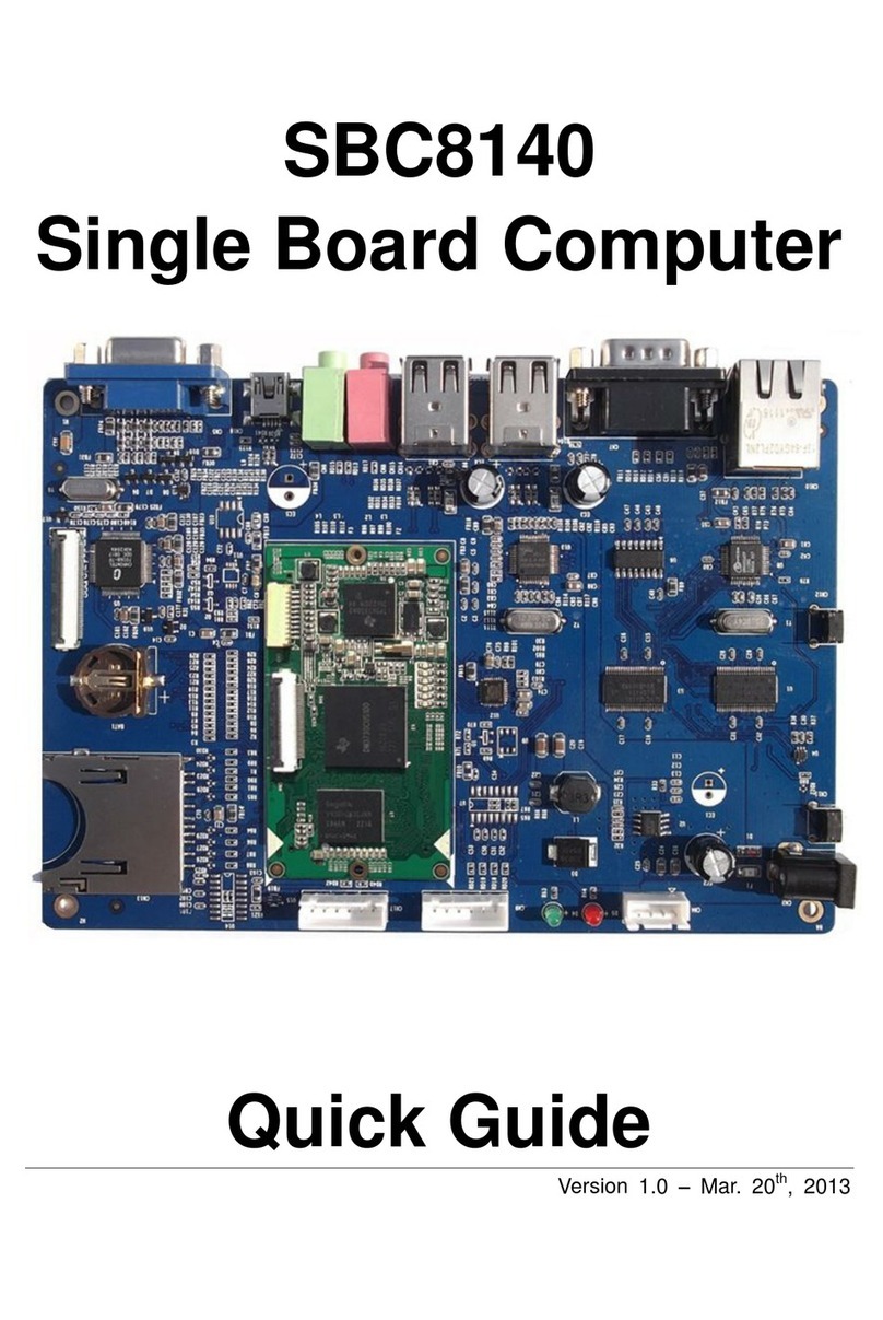
Embest SBC8140 User manual

SBC8140
Single Board Computer
User Manual
Version 1.1
22nd Jan 2014

Copyright Statement:
SBC8140 and its related intellectual property are owned by
Shenzhen Embest Technology Co., Ltd.
Shenzhen Embest Technology has the copyright of this document
and reserves all rights. Any part of the document should not be
modified, distributed or duplicated in any approach and form
without prior written permission issued by Embest Technology Co.,
Ltd.
Revision History:
Version
Date
Description
1.0
20/03/2013
Original Version
1.1
22/01/2014
Localisation

Table of Contents
1 Product Overview ............................................................ 1
1.1 Introduction ................................................................. 1
1.2 Kit Contents ................................................................. 1
1.3 Product Features........................................................... 2
1.3.1 Mini8510 Core Board ............................................................... 2
1.3.2 Expansion Board ..................................................................... 4
1.4 Interfaces on the SBC8140 ............................................. 6
1.5 System Block Diagram ................................................... 7
1.6 Hardware Dimensions .................................................... 8
1.6.1 MINI8510 Core Board .............................................................. 8
1.6.2 Expansion Board ..................................................................... 9
1.7 Modules Supported by SBC8140 .....................................10
2 Introduction to Hardware .............................................. 11
2.1 CPU Introduction..........................................................11
2.1.1 Clock ................................................................................... 11
2.1.2 Reset ...................................................................................11
2.1.3 General Interfaces .................................................................11
2.1.4 Display Subsystem.................................................................12
2.1.5 3D Graphics Acceleration System .............................................12
2.2 Peripheral ICs around CPU.............................................13
2.2.1 TPS65930 Power Management IC .............................................13
2.2.2 H9DA4GH2GJAMCR Memory .................................................... 14
2.2.3 DM9000 Ethernet Controller..................................................... 14
2.2.4 FE1.1 USB Hub ...................................................................... 14
2.2.5 TFP410 Flat Panel Display IC.................................................... 14
2.2.6 MAX3232 Transceiver ............................................................. 15
2.3 Hardware Interfaces and LEDs on Mini8510 ......................16
2.3.1 CN1 90pin DIP Interface (right row) ..........................................16

2.3.2 CN2 90pin DIP Interface (left row) ............................................21
2.3.3 CN3 JTAG Interface ................................................................ 25
2.3.4 CN4 Camera Interface ............................................................ 25
2.3.5 LED Indicators.......................................................................27
2.4 Interfaces on Expansion Board .......................................27
2.4.1 Power Jack ........................................................................... 28
2.4.2 TFT_LCD Interface .................................................................28
2.4.3 Audio Output Interface ........................................................... 31
2.4.4 Audio Input Interface.............................................................. 31
2.4.5 Serial Interface...................................................................... 31
2.4.6 Ethernet Interface..................................................................32
2.4.7 USB OTG Interface ................................................................. 32
2.4.8 USB HOST Interface ............................................................... 33
2.4.9 SD Card Interface .................................................................. 33
2.4.10 LED Indicators .....................................................................34
2.4.11 Buttons ..............................................................................34
3 Linux Operating System ................................................. 35
3.1 Structure of the Embedded Linux System.........................35
3.2 Software Features ........................................................36
3.3 System Development Process ........................................37
3.3.1 Building Development Environment...........................................37
3.3.2 System Compilation ............................................................... 38
3.3.3 Customizing the System.......................................................... 41
3.4 Introduction to Drivers..................................................42
3.4.1 NAND Flash Driver ................................................................. 45
3.4.2 SD/MMC Driver......................................................................46
3.4.3 Display Subsystem Driver........................................................ 47
3.4.4 Video Capture Driver .............................................................. 48
3.4.5 Audio Input/Output Driver .......................................................50
3.5 Driver Development .....................................................51
3.5.1 GPIO_Keys Driver ..................................................................51
3.5.2 GPIO_LEDs Driver .................................................................. 56
3.6 System Update ............................................................61
3.6.1 Updating System in an SD Card................................................61
3.6.2 Updating System in NAND Flash ...............................................70
3.7 Display Mode Configuration ...........................................72
3.8 Tests and Demonstrations .............................................74
3.8.1 Testing LEDs ......................................................................... 74
3.8.2 Testing a Touch-Screen........................................................... 75
3.8.3 Testing the RTC ..................................................................... 75
3.8.4 Testing an SD Card ................................................................ 76
3.8.5 Testing a USB Device.............................................................. 77
3.8.6 Testing USB HOST ................................................................. 79
3.8.7 Testing the Audio Function ...................................................... 80
3.8.8 Testing the Network Connection ...............................................81
3.8.9 Testing the Camera ................................................................ 82
3.8.10 Testing the CDMA8000-U Module ............................................ 83
3.8.11 Testing the WCDMA8000-U Module .........................................83
3.8.12 Demonstration of the Android System......................................84
3.8.13 Demonstration of the DVSDK System ......................................86
3.9 Development of Applications ..........................................88
4 WinCE Operating System................................................ 90
4.1 Software Resources ......................................................90
4.2 BSP Package Contents ..................................................91
4.3 Process of System Development.....................................93
4.3.1 Installing the IDE...................................................................93
4.3.2 Uncompressing/Copying the BSP and Example Projects ................93
4.3.3 Compiling Sysgen and the BSP .................................................94
4.4 Introduction to Drivers..................................................95
4.5 System Update ............................................................98
4.5.1 Updating the System in an SD Card .......................................... 98
4.5.2 Updating the System in NAND Flash ........................................ 102
4.6 Other Operations ....................................................... 103

4.6.1 OpenGL ES demo ................................................................. 103
4.6.2 CAM8000-A Module .............................................................. 104
4.6.3 CAM8000-D Module.............................................................. 105
4.7 GPIO API and Example Applications .............................. 107
Appendix 1: Installing an Ubuntu Linux System............... 111
1.1 Installing VirtualBox ................................................... 111
1.2 Installing the Ubuntu Linux System............................... 116
Appendix 2: Driver Installation Of Linux USB
Ethernet/RNDIS Gadget.................................................. 123
Appendix 3: Making a Linux Boot Disk ............................. 126
Appendix 4: TFTP Server Setup ....................................... 131
Appendix 5: FAQ ............................................................. 133
Appendix 1: ESD Precautions & Handling Procedures....... 134
Appendix 2: Technical support & Warranty...................... 135
2.1 Technical support service ............................................ 135
2.2 Maintenance service clause.......................................... 136
2.3 Basic guidelines for protection and maintenance of LCDs .. 137
2.4 Value Added Services ................................................. 138

Page | 1
1Product Overview
1.1 Introduction
The SBC8140 is a Single Board Computer designed by Embest using the
MINI8510 processor card as the CPU core board. The MINI8510 is built
around the DM3730 microcontroller featuring 256MByte DDR SDRAM,
512MByte NAND Flash, RTC, LEDs, Camera interface and a 10-pin JTAG
interface on board. It is connected with the SBC8140 expansion board
through two 1.27mm space 2x45-pin dip connectors. The SBC8140
expansion board utilises many of other features of the DM3730 through
headers and connectors including serial ports, USB Host, OTG, Ethernet,
Audio In/Out, Keyboard, LCD/Touch Screen interface, VGA, SD card, etc.
The board targets those applications requiring high definition video or
large-scale data processing such as:
2D/3D game console products,
Portable media devices,
High-end industrial equipment,
Medical devices,
Intelligent home systems.
1.2 Kit Contents
SBC8140
Cross-over serial cable (DB9 to DB9)
10-pin JTAG cable
JTAG8000 module
5V/2A power adapter
DVD-ROM
Optional LCD screen (available in 4.3”480x272 or 7”800x480)

Page | 2
1.3 Product Features
1.3.1 Mini8510 Core Board
Figure 1: Back of MINI8510 Figure 2: Top of MINI8510
Operational Parameters:
Dimensions: 67x37mm
Operation Temperature: 0 ~ 70°C
Operating Humidity: 20% ~ 90% (Non-condensing)
Power Supply: 3.3V/0.17A
Processor:
TI DM3730 integrating a 1GHz ARM Cortex™-A8 core
800-MHz TMS320C64x+™ DSP
NEON™ SIMD co-processor
POWERVR SGX™ graphic accelerator
32KB instruction buffer, 32KB data buffer, 256KB L2 cache, 64KB
RAM and 32KB ROM

Page | 3
On-Board Memories:
256MB 32bit DDR SDRAM
512MB 16bit NAND Flash
Interfaces and Signals:
Camera interface (supports external CCD or CMOS camera)
JTAG interface
Two 1.27mm-pitch 90-pin DIP connectors
Six LED indicators (two power indicators and four custom user
indicators)
Two SPIs: SPI1 and SPI2
GPMC bus (16-bit data, 10-bit address, four CS and some control
signals)
Three UARTs (5-wire, support hardware flow control)
ULPI (USB1 HS)
Audio input and output
IIC bus (IIC3)
Two McBSPs: McBSP1 and McBSP3 (McBSP3 is multiplexed on
UART2)
Two MMCs/SDs:MMC1 (8-wire) and MMC2 (4-wire)
24-bit DSS interface

Page | 4
1.3.2 Expansion Board
Figure 3: SBC8140 Expansion Board
Operational Parameters:
Dimensions: 165x115mm
Operation temperature: 0 ~ 70°C
Operating Humidity: 20% ~ 90% (Non-condensing)
Power Supply: 5V/2A
Audio/Video Interfaces:
LCD/touch-screen interface (24-bit RGB full-colour output; 50-pin
FPC connector)
Standard VGA interface, supports 1024x768 resolution by default
Audio input interface (3.5mm audio jack)
Dual-channel audio output interface (3.5mm audio jack)
Data transfer interface:

Page | 5
10/100Mbps Ethernet interface (RJ45 connector)
High-speed USB 2.0 OTG interface with PHY (480Mbps mini-USB
interface)
Four high-speed USB 2.0 HOST interfaces with PHY (480Mbps
USB-A interface)
SD card slot (compatible with SD/MMC communication)
Serial Interfaces:
Interfaces
Descriptions
UART1
5-wire, RS232 voltage level, DB9 debugging serial interface
UART2
3-wire, TTL voltage level, 6-pin connector
UART3
5-wire, TTL voltage level, 6-pin connector
Input Interfaces:
BOOT button
Reset button
LED indicators:
Power indicator
Two custom user indicators

Page | 6
1.4 Interfaces on the SBC8140
Figure 4: SBC8140 Interfaces

Page | 7
1.5 System Block Diagram
Figure 5: SBC8140 system block diagram

Page | 8
1.6 Hardware Dimensions
1.6.1 MINI8510 Core Board
Figure 6: MINI8510 dimensions (top side)
Figure 7: MINI8510 dimensions (back side)

Page | 9
1.6.2 Expansion Board
Figure 8: Expansion board dimensions

Page | 10
1.7 Modules Supported by SBC8140
Modules
Linux
Android
WinCE
Materials
WF8000-U
Yes*
NO
Yes#
Provided with CD-ROM
Separately
CAM8000-A
Yes*
Yes*
Yes*
Available in CD
CAM8000-D
Yes
NO
Yes*
Click to download
CAM8100-U
Yes*
Yes*
Yes
Provided with CD-ROM
Separately
CDMA8000-U
Yes*
No
Yes
Click to download
WCDMA8000-U
Yes*
No
Yes
Click to download
LVDS8000
Yes*
Yes*
Yes*
Available on CD and website
*=Source code provided

Page | 11
2Introduction to Hardware
This chapter will help you learn about the hardware composition of the
MINI8510 core board by briefly introducing CPU, peripheral ICs and pin
definitions of various interfaces on the product (MINI8510+Expansion
board).
2.1 CPU Introduction
The MINI8510 core board uses the DM3730 –TI’s 45-nm
high-performance processor with low power and enhanced digital media
processing capability. The CPU has a 1GHz Cortex-A8 core and an 800MHz
TMS320C64+ DSP core, and also integrates a 3D graphics processing unit,
an imaging and video accelerator and USB 2.0, making it capable of 720p
video coding and decoding.
2.1.1 Clock
The clock signals of the DM3730 include sys_32k, sys_altclk, sys_clkout1,
sys_clkout2, sys_xtalout, sys_xtalin and sys_clkreq, among which:
sys_32k: the frequency is 32 KHz, generated by the TPS65930
power management chip and used for low-frequency calculation;
low-power mode is enabled through sys_32k pin.
sys_xtalou and sys_xtalin: are system input clocks with a
frequency of 26MHz and are used to provide primary clocks for
DPLLs and other modules.
2.1.2 Reset
Reset signal is determined by SYS_NRESPWRON of the CPU; a low level
validates resetting.
2.1.3 General Interfaces
General interfaces include 6 sets of GPIOs, each of which provides 32
dedicated GPIO pins, and therefore the total pin number of GPIOs can be
up to 192 (6×32). These pins can be configured for different applications
such as data input/output (driver), keypad interface and terminal control.

Page | 12
2.1.4 Display Subsystem
The display subsystem is used to provide an LCD or TV interface with logic
images which are stored in the frame buffer (SDRAM or SRAM); it is made
up of:
Display control (DISPC) module
Remote frame buffering interface (RFBI) module
I/O module and DSI protocol engine of the display serial interface
(DSI)
DSI PLLcontroller driver (DSI PLL and high-speed frequency divider
NTSC/PAL video codec
The display controller and DSI protocol engine are connected to the
internal bus of L3 and L4, while the RFBI and TV output codec module are
connected to the internal bus of L.
2.1.5 3D Graphics Acceleration System
The 2D/3D graphics acceleration system (SGX) can speed up 2D/3D
graphic applications. The SGX system is built on the POWERVR® SGX core
from Imagination Technologies. It is a new-generation of programmable
POWERVR graphics core. POWERVR SGX530 v1.2.5 has an adaptable
architecture which makes it suited for a wide range of applications from
main-stream mobile devices to high-end desk-top graphics processing. Its
target applications are mainly feature phones, PDAs and some portable
game consoles.

Page | 13
Figure 9: SGX Graphics Acceleration System
The architecture of the SGX graphics acceleration system allows for
switching among multiple threads by adopting two-level scheduling and
data partitioning, so that it is capable of processing pixels, vertexes, videos
and general data.
2.2 Peripheral ICs around CPU
2.2.1 TPS65930 Power Management IC
The TPS65930 is a power-management IC for OMAP families. The device
includes power-management, a USB high-speed transceiver, LED drivers,
an analogue-to-digital converter (ADC), a real-time clock (RTC), and
embedded power control (EPC). In addition, the TPS65930 includes a full
audio codec with two digital-to-analogue converters (DACs) and two ADCs
to implement dual voice channels, and a stereo downlink channel that can
play all standard audio sample rates through a multiple format
inter-integrated sound (I2S™)/time division multiplexing (TDM) interface.

Page | 14
The TPS65930 communicates with the CPU through the I2C protocol. It
supplies 1.2V and 1.8V to keep CPU working properly. Additionally, the
TPS65930 features Audio in, Audio out, OTG PHY, Keyboard, ADC and
GPIO functions.
2.2.2 H9DA4GH2GJAMCR Memory
The H9DA4GH2GJAMCR is a two-in-one memory which combines 512MB of
NAND Flash and 256MB of SDRAM DDR. The NAND Flash is accessed
through the GPMC bus, while the SDRAM is accessed through the
Controller (SDRC).
2.2.3 DM9000 Ethernet Controller
The DM9000 is a fully integrated fast Ethernet controller with a general
processor interface, a 10/100M PHY and 4K DWORD SRAM. It supports
3.3V with a 5V tolerance.
The SBC8140 uses the 10/100M self-adaptive network interface of the
DM8000 which is a standard RJ45 interface with connection and data
transfer indicators. The 10/100M Ethernet module integrated in the
DM9000 is compliant with the IEEE 802.3 standard.
The SBC8140 can be either connected to a hub with a straight-through
network cable, or to a PC with a cross-over network cable.
2.2.4 FE1.1 USB Hub
FE1.1 is a USB 2.0 high-speed 4-port hub solution. It uses the USB3320 to
provide 4 extended USB interfaces with support for high-speed (480MHz),
full-speed (2MHz) and low-speed (1.5MHz) modes.
2.2.5 TFP410 Flat Panel Display IC
The TFP410 is a Texas Instruments PanelBus flat panel display product,
part of a comprehensive family of end-to-end DVI 1.0-compliant solutions,
targeted at the PC and consumer electronics industry.
The TFP410 provides a universal interface to allow glue-less connection to
most commonly available graphics controllers. Some of the advantages of
this universal interface include selectable bus widths, adjustable signal
levels, and differential and single-ended clocking. The adjustable 1.1V to
1.8V digital interface provides a low-EMI, high-speed bus that connects
Other manuals for SBC8140
1
Table of contents
Other Embest Single Board Computer manuals
Popular Single Board Computer manuals by other brands

Variscite
Variscite VAR-OM35CustomBoard v2.3 DIAGRAMS

Motorola
Motorola MVME177 Installation and use manual

VIA Technologies
VIA Technologies VAB-800 user manual

SBS Technologies
SBS Technologies V5C Technical manual

SMART Embedded Computing
SMART Embedded Computing MVME3100 quick start guide

Lanner electronics
Lanner electronics PC/104 Single Board Computer with STPC Atlas CPU, and VGA, LCD, LAN, SSD, on-board RAM, 4xCOM,... user manual