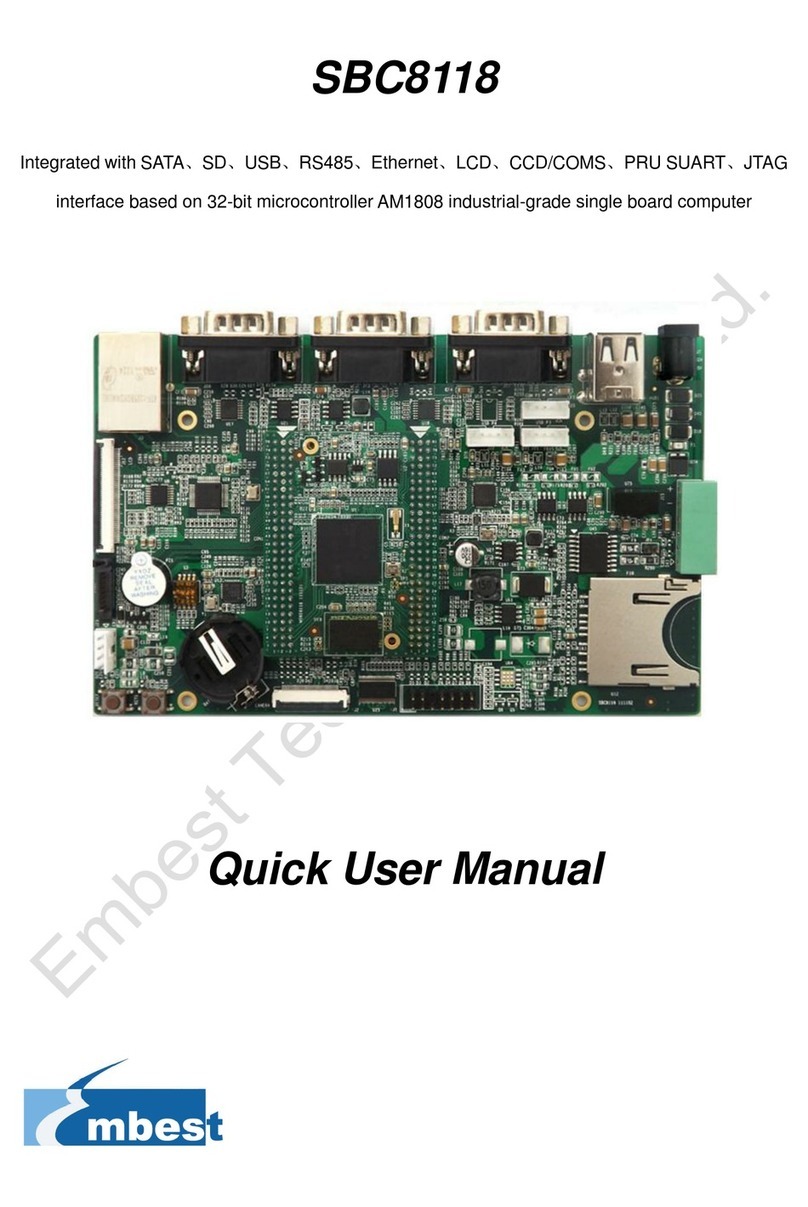
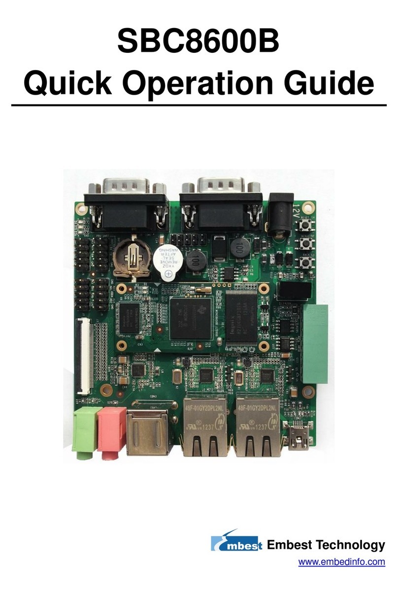
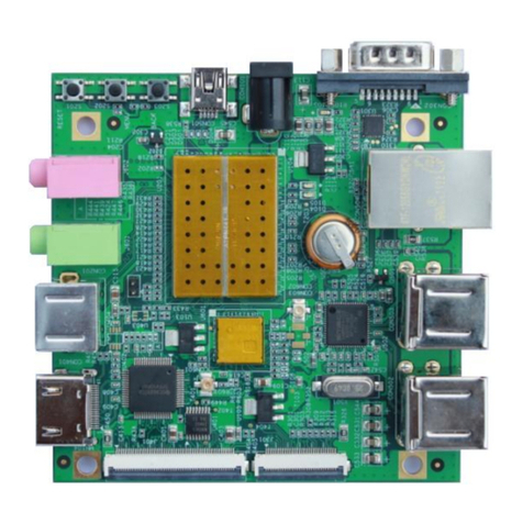
Embest SBC8600B User manual

SBC8600B
Single Board Computer
Quick Start Guide
Version 1.1
23rd Jan 2014

Copyright Statement:
SBC8600B and its related intellectual property are owned by
Shenzhen Embest Technology Co., Ltd.
Shenzhen Embest Technology has the copyright of this document and
reserves all rights. Any part of the document should not be modified,
distributed or duplicated in any approach and form without prior
written permission issued by Embest Technology Co., Ltd.
Revision History:
Version
Date
Description
1.0
21/12/2012
Original Version
1.1
23/01/2014
Localisation

Table of Contents
1 Product Overview .............................................................. 1
1.1 Introduction....................................................................1
1.2 Kit Contents....................................................................1
1.3 Board Interfaces..............................................................2
1.4 System Block Diagram .....................................................3
1.5 Physical Dimensions.........................................................4
2 Hardware Features ............................................................ 6
2.1 Processor .......................................................................6
2.2 On-Board Memory ...........................................................6
2.3 On-Board Interfaces ........................................................6
2.4 Operational Parameters ....................................................7
3 Hardware Details............................................................... 8
3.1 Introduction to CPU .........................................................8
3.2 CPU Features ..................................................................8
3.2.1 Clock........................................................................................ 8
3.2.2 Reset ....................................................................................... 8
3.2.3 General-Purpose Interfaces......................................................... 9
3.2.4 Programmable Real-Time Unit Subsystem..................................... 9
3.2.5 3D Graphics Engine.................................................................... 9
3.3 Introduction to Peripherals................................................9
3.3.1 NAND Flash H27U4G8F2DTR-BC .................................................. 9
3.3.2 DDR H5TQ2G83CFR-H9C .......................................................... 10
3.3.3 Ethernet AR8035 ..................................................................... 10
3.3.4 MAX3232 ................................................................................ 10
4 Hardware Interfaces ....................................................... 11

4.1 MINI8600B ...................................................................11
4.1.1 CN1 Interface.......................................................................... 11
4.1.2 CN2 Interface.......................................................................... 15
4.2 Extension Board ............................................................19
4.2.1 Power Jack.............................................................................. 19
4.2.2 TFT_LCD Interface ................................................................... 20
4.2.3 Audio Output Interface ............................................................. 22
4.2.4 Audio Input Interface ............................................................... 23
4.2.5 USB HOST Interface ................................................................. 23
4.2.6 USB OTG Interface................................................................... 23
4.2.7 TF Card Interface..................................................................... 24
4.2.8 LAN Interface .......................................................................... 24
4.2.9 Serial Interface........................................................................ 25
4.2.10 CAN&RS485 Interface............................................................. 25
4.2.11 ADC Interface........................................................................ 26
4.2.12 SPI Interface ......................................................................... 26
4.2.13 Extension Interface ................................................................ 27
4.2.14 Buttons................................................................................. 28
4.2.15 LEDs .................................................................................... 28
5 Linux Operating System .................................................. 29
5.1 Introduction.................................................................. 29
5.2 Software Resources .......................................................29
5.3 Software Features .........................................................30
5.4 System Development .....................................................31
5.4.1 Establishment of development environment ................................ 31
5.4.2 Installing Cross Compilation Tools.............................................. 31
5.4.3 Addition of environment variables .............................................. 32
6 Establishment of Android Development Environment ...... 33
6.1 System Compilation .......................................................33
6.1.1 Preparation ............................................................................. 33
6.1.2 Compilation of boot code .......................................................... 34

6.1.3 Kernel compilation ................................................................... 34
6.2 Generation of the file system .......................................... 34
6.2.2 Android system compilation ...................................................... 35
6.3 System Customization....................................................36
6.3.1 Modification of Kernel Configuration ........................................... 36
6.3.2 Compilation............................................................................. 37
6.4 Introduction to Drivers ...................................................38
6.4.1 NAND ..................................................................................... 38
6.4.2 SD/MMC ................................................................................. 39
6.4.3 LCDC...................................................................................... 40
6.4.4 Audio in/out ............................................................................ 41
6.5 Driver Development .......................................................42
6.5.1 Driver for the gpio_keys ........................................................... 42
6.5.2 Driver for the gpio_leds ............................................................ 47
6.6 Updating the System......................................................50
6.6.1 Updating the TF card system image ........................................... 50
6.6.2 Updating NAND Flash ............................................................... 54
6.7 Instructions ..................................................................56
6.7.1 Selecting the Display Mode ....................................................... 56
6.7.2 Using a 4.3” LCD Display .......................................................... 57
6.7.3 Using a 7” LCD Display ............................................................. 58
6.7.4 Using a VGA Display................................................................. 58
6.7.5 Using an LVDS Display ............................................................. 58
6.8 Testing.........................................................................58
6.8.1 LED Testing............................................................................. 58
6.8.2 KEYPAD Testing....................................................................... 58
6.8.3 Touch Screen Testing ............................................................... 60
6.8.4 Backlight Testing ..................................................................... 60
6.8.5 RTC Testing ............................................................................ 61
6.8.6 TF Card Testing ....................................................................... 62
6.8.7 USB DEVICE Testing ................................................................ 63
6.8.8 USB HOST Testing ................................................................... 65
6.8.9 AUDIO Testing......................................................................... 66
6.8.10 Network Testing..................................................................... 68
6.8.11 CAN Testing........................................................................... 69
6.8.12 RS485 Testing ....................................................................... 71
6.8.13 Serial Interface Testing ........................................................... 72
6.8.14 Buzzer Testing....................................................................... 72
6.8.15 CDMA8000-U Module.............................................................. 73
6.9 Demo........................................................................... 73
6.9.1 Android System Demonstration ................................................. 73
6.9.2 TISDK System Demonstration ................................................... 75
6.10 Application Development ..............................................77
6.10.1 Development example: LED application program ....................... 77
7 WinCE Operating System ................................................. 79
7.1 Introduction.................................................................. 79
7.2 Software Resources .......................................................79
7.3 Software Features .........................................................80
7.4 System Development .....................................................81
7.4.1 Installation of Integrated Development Environment .................... 81
7.4.2 Extract BSP and project files to the IDE ...................................... 81
7.4.3 Sysgen & Build BSP.................................................................. 82
7.4.4 Driver Introduction .................................................................. 83
7.5 Updating the System Image............................................84
7.5.1 Update TF Card Image ............................................................. 84
7.5.2 Update NAND Flash image ........................................................ 90
7.6 Instructions for Use ....................................................... 90
7.6.1 How To Use openGL ES Demo ................................................... 90
7.7 Application Development ................................................91
7.7.1 Application Program Interfaces and Examples ............................. 91
7.7.2 GPIO Application Program Interfaces and Examples ..................... 91
Appendix 1: Installing an Ubuntu Linux System ................. 94
1.1 Installing VirtualBox.......................................................94

1.2 Installing the Ubuntu Linux System..................................99
Appendix 2: Driver Installation Of Linux USB Ethernet/RNDIS
Gadget 105
Appendix 3: Making a Linux Boot Disk.............................. 108
Appendix 4: TFTP Server Setup ........................................ 113
Appendix 5: ESD Precautions & Handling Procedures....... 115
Appendix 6: Technical support & Warranty ...................... 116
6.1 Technical support service.............................................. 116
6.2 Maintenance service clause ........................................... 117
6.3 Basic guidelines for protection and maintenance of LCDs .. 118
6.4 Value Added Services................................................... 119

Page | 1
1Product Overview
1.1 Introduction
Measuring only 60mm by 27mm, the MINI8600B processor card is a small
form-factor controller board based on TI’s Sitara AM3359 ARM Cortex-A8
processor. The tiny module integrates 2x256MB of DDR3 SDRAM and 512MB
of NAND Flash and uses two 0.4mm space 2x40-pin board-to-board male
expansion connectors to bring out many hardware peripheral signals and
GPIOs from the CPU.
Embest has designed a single board computer SBC8600B which has an
expansion board to carry the Mini8600B. The flexible design allows the fast
and easy way of realizing and upgrading the controller’s capabilities. In
addition to those features offered by Mini8600B, the SBC8600B features 5
serial ports (including 2 RS232 and 3 TTL), 2 USB Host and 1 USB OTG, 2
Ethernet ports, CAN, RS485, LCD, Touch screen, Audio, ADC and many
other peripherals. The SBC8600B is a ready-to-run platform with support for
Linux 3.2.0, Android 2.3 and WinCE 7 operating systems.
1.2 Kit Contents
SBC8600B Board
12V Power Adapter
Cross Over Serial Cable
Ethernet Cable
DVD
Optional 4.3” or 7” LCD

Page | 2
1.3 Board Interfaces
Figure 1: SBC8600B Interfaces

Page | 3
1.4 System Block Diagram
Figure 2: SBC8600B System Block Diagram

Page | 4
1.5 Physical Dimensions
Figure 3: MINI8600B Physical Dimensions

Page | 5
Figure 4: SBC8600B Physical Dimensions

Page | 6
2Hardware Features
2.1 Processor
720-MHz ARM Cortex™-A8 32-Bit RISC Microprocessor
NEON™ SIMD Coprocessor
32KB/32KB of L1 Instruction/Data Cache with Single-Error Detection
(parity)
256KB of L2 Cache with Error Correcting Code (ECC)
SGX530 Graphics Engine
Programmable Real-Time Unit Subsystem
2.2 On-Board Memory
512MB NAND Flash
Two x 256MB DDR3 SDRAM (512MB total)
2.3 On-Board Interfaces
Two 0.4-pitch 2x40-pin DIP Interfaces
A TFT LCD Interface (Support LCDs with 24-bpp parallel RGB
interface)
Two USB2.0 High-Speed OTG Interfaces
Six UART Interfaces
SPI Interface
Two 10/100 /1000Mb/s Ethernet MAC(EMAC) with Management Data
Input/Output(MDIO) Module
A Multichannel Audio Serial Ports (McASP)
8-Channel 12bit ADC Interface
Three IIC Signals
Two 4-line SD/MMC card interfaces

Page | 7
GPMC Signals
Note:
Some of the pins are multiplexed for UART、IIC、SPI、CAN. Please refer to the
CPU datasheet and schematics on the DVD for details.
2.4 Operational Parameters
Working Temperature: 0 °C~ 70°C
Working Humidity: 20% ~ 90%, Non-Condensing
Dimensions: 60mm x 27mm
Input Voltage: 3.3V

Page | 8
3Hardware Details
3.1 Introduction to CPU
The AM335x microprocessors, based on the ARM Cortex-A8, are enhanced
with image and graphics processing, peripherals, and industrial interface
options such as EtherCAT and PROFIBUS. The device has support for
high-level operating systems such as Linux, WinCE and Android.
The AM335x microprocessor contains these subsystems:
Microprocessor unit (MPU) subsystem based on the ARM Cortex-A8
microprocessor.
POWERVR SGX™ Graphics Accelerator subsystem for 3D graphics
acceleration to support display and gaming effects.
The Programmable Real-Time Unit and Industrial Communication
Subsystem (PRU-ICSS) is separate from the ARM core, allowing
independent operation and clocking for greater efficiency and
flexibility.
3.2 CPU Features
3.2.1 Clock
The AM3359 has two clock inputs, OSC1 and OCC0, and two clock outputs,
LCKOUT1 and LCKOUT2.
OSC1 provides RTC with a 32.768KHz reference clock. And it is used to
connect RTC_XTALIN terminal to RTC_XTALOUT terminal.
OSC0 provides reference clocks such as 19.2-MHz, 24-MHz, 25-MHz or
26-MHz for the clocks without RT function. It is also used to connect the
XTALIN terminal and the XTALOUT terminal.
3.2.2 Reset
Resetting is controlled by PWRONRSTn signals from the CPU. The device is
reset when there is a low level signal.

Page | 9
3.2.3 General-Purpose Interfaces
There are 4 GPIO banks, each of which has 32 I/O pins, giving a total pin
number of 128 (4x32).
3.2.4 Programmable Real-Time Unit Subsystem
The PRUSS of AM3359 consists of 2 programmable real-time units; a 12KB
shared RAM with single-error detection (parity), tree 120B register bank
that can be accessed by each PRU, an interrupt controller module used to
process input events of the system, and the following peripherals:
UART with data flow control and maximum rate of 12Mbps
Two MII Ethernet interfaces with support for industrial Ethernet such
as EtherCAT™
A MDIO interface
An enhanced capture module (eCAP)
3.2.5 3D Graphics Engine
The POWERVR SGX graphics acceleration subsystem is used to improve 3D
image processing, as well as to provide regular display and gaming effects.
The subsystem features:
Tile-Based Architecture Delivering Up to 20 MPloy/sec
Universal Scalable Multi-Threaded Shader Engine Incorporating Pixel
and Vertex Shader Functionality
Advanced Shader Feature Set in Excess of Microsoft VS3.0, PS3.0 and
OGL2.0
Industry Standard API Support of Direct3D Mobile, OGL-ES 1.1 and
2.0, OpenVG 1.0, and OpenMax
3.3 Introduction to Peripherals
3.3.1 NAND Flash H27U4G8F2DTR-BC
The H27U4G8F2DTR-BC is a 512M NAND Flash used on SBC8600B.

Page | 10
If you need more information about the NAND Flash, please refer to
H27U4G8F2DTR-BC.pdf under Disk-SBC8600B\HW design\datasheet\
NAND Flash\
3.3.2 DDR H5TQ2G83CFR-H9C
The H5TQ2G83DFR-H9C is a 256MB DDR3 SDRAM used on SBC8600B.
There are two H5TQ2G83DFR-H9Cs on SBC8600B.
If you need to know more about the SDRAM, please refer to
H5TQ2G83DFR.pdf under Disk-SBC8600B\HW design\datasheet\DDR\.
3.3.3 Ethernet AR8035
AR8035 is a low-power and low-cost Ethernet PHY used on SBC8600B and
integrated with a 10/100/1000Mb transceiver. It is a single-port tri-speed
Ethernet PHY and supports MAC.TM RGMII interfaces.
AR8035 is compliant with the IEEE 802.3az Energy Efficiency Ethernet
Standard and the Atheros’s proprietary SmartEEE standard, which allows
traditional MAC/SoC devices incompatible with 802.3az to function as a
complete 802.3az system.
SBC8600B can be connected to a hub with a straight-though network cable,
or connected to a computer with a crossover cable.
If you need know more about the Ethernet chip, please refer to AR8035.pdf
under Disk-SBC8600B\HW design\datasheet\LAN\.
3.3.4 MAX3232
MAX3232 is used to convert TTL levels into RS232 levels so that the board
can communicate with the RS232 interfaces of PCs.
SBC8600B uses UART0 as a debugging serial interface. The default voltage
of UART0 is 1.8V, which needs to be boosted up to 3.3V for use with RS232.
If you need to know more about this chip, please refer to MAX3232CSE.pdf
under Disk-SBC8600B\HW design\datasheet\ Serial\.

Page | 11
4Hardware Interfaces
4.1 MINI8600B
4.1.1 CN1 Interface
Figure 5: MINI8600B CN1 Interface
CN1
PIN
Signal
Function
1
GND
GND
2
VDDS_RTC
Supply voltage for RTC
3
CLK_OUT1
Clock out1
4
CLK_OUT2
Clock out2
5
MMC0_DAT0
MMC0 data bus
6
MMC0_DAT1
MMC0 data bus
7
MMC0_DAT2
MMC0 data bus
8
GLOBLE_RESETN
SYS_RESET IN/ OUTPUT
9
MMC0_DAT3
MMC0 data bus
10
AM335X_PWRON_RESETN
CPU PWRON Reset
11
GND
GND
12
GND
GND
13
AM355X_PRU_UART0_CTS
PRU UART0 Clear To Send

Page | 12
CN1
PIN
Signal
Function
14
AM355X_PRU_UART0_RX
PRU UART0 receive data
15
AM355X_PRU_UART0_RTS
PRU UART0 request to send
16
AM355X_PRU_UART0_TX
PRU UART0 transmit data
17
AM355X_UART0_RX
UART0 receive data
18
AM355X_UART3_RX
UART3 receive data
19
AM355X_UART0_TX
UART0 transmit data
20
AM355X_UART3_TX
UART3 transmit data
21
AM355X_CAN0_RX
CAN0 receive data
22
AM355X_I2C0_SDA
I2C0 master serial data
23
AM355X_CAN0_TX
CAN0 transmit data
24
AM355X_I2C0_SCL
I2C0 master serial clock
25
AM355X_UART4_RX
UART4 receive data
26
AM355X_UART1_RX
UART1 receive data
27
AM355X_UART4_TX
UART4 transmit data
28
AM355X_UART1_TX
UART1 transmit data
29
GND
GND
30
GND
GND
31
MII1_COL
MII1 collision detect
32
AM355X_USB0_DRVVBUS
USB0 controller VBUS control
output
33
MII1_TX_CLK
MII1 transmit clock
34
AM355X_USB1_DRVVBUS
USB1 controller VBUS control
output
35
MII1_TX_EN
MII1 transmit enable
36
MII1_REF_CLK
MII1 reference clock

Page | 13
CN1
PIN
Signal
Function
37
MII1_TXD3
MII1 transmit data
38
MII1_CRS
MII1 carrier sense
39
MII1_TXD2
MII1 transmit data
40
MII1_RX_ER
MII1 receive data error
41
MII1_TXD1
MII1 transmit data
42
MII1_RX_DV
MII1 receive data valid
43
MII1_TXD0
MII1 transmit data
44
MII1_RX_CLK
MII1 receive clock
45
MII_MDIO
MII MDIO DATA
46
MII1_RXD3
MII1 receive data
47
MII_MDC
MII MDIO CLK
48
MII1_RXD2
MII1 receive data
49
GND
GND
50
MII1_RXD1
MII1 receive data
51
AM355X_USB0_DM
USB0 DM-
52
MII1_RXD0
MII1 receive data
53
AM355X_USB0_DP
USB0 DP
54
MMC0_CMD
MMC0 Command Signal
55
GND
GND
56
USB0_VBUS
USB0 bus voltage
57
AM355X_USB1_DM
USB1 data-
58
AM355X_USB1_ID
USB1 ID
59
AM355X_USB1_DP
USB1 data+
60
AM355X_USB0_ID
USB0 ID
Other manuals for SBC8600B
3
Table of contents
Other Embest Single Board Computer manuals
Popular Single Board Computer manuals by other brands

Variscite
Variscite VAR-OM35CustomBoard v2.3 DIAGRAMS

Motorola
Motorola MVME177 Installation and use manual

VIA Technologies
VIA Technologies VAB-800 user manual

SBS Technologies
SBS Technologies V5C Technical manual

SMART Embedded Computing
SMART Embedded Computing MVME3100 quick start guide

Lanner electronics
Lanner electronics PC/104 Single Board Computer with STPC Atlas CPU, and VGA, LCD, LAN, SSD, on-board RAM, 4xCOM,... user manual