EMBRON Hatteland Technology HTC03 AC Series User manual
Please visit www.hattelandtechnology.com for the latest electronic version of this manual.
USER MANUAL
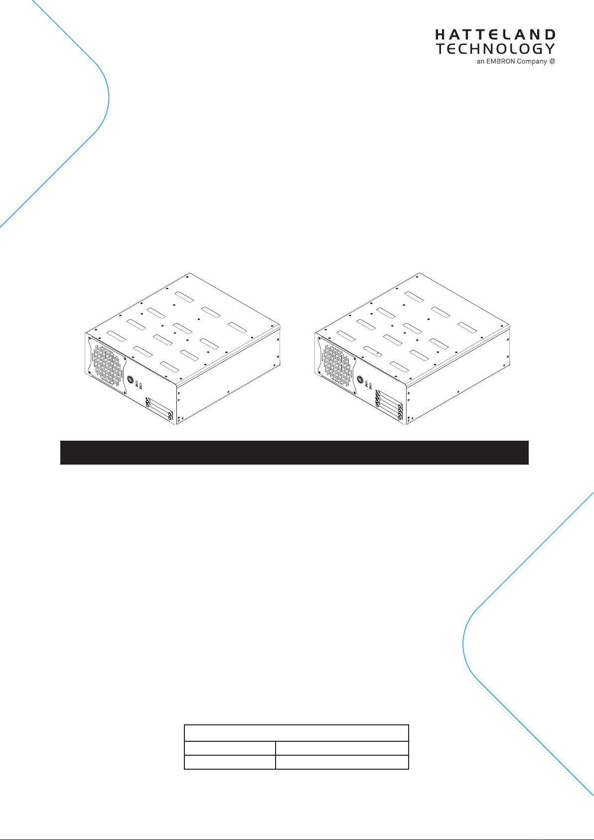
4-Bay Model
2-Bay Model
HTC03 - Compact Computer
User Manual HTC03
Updated: 28 May 2021 Doc Id: INB100042-6 (Rev 02)
Created: 7495/363 Approved: 6987
Models:
HTC03-xx-AC yzzzzzz (Single AC power input)
HTC03-xx-MP yzzzzzz (Multi-Power AC+DC inputs)
where xx=CPU type (i3,i5,i7), y=manufacturing site, zz=conguration

Copyright © 2020 Hatteland Technology AS
Eikeskogvegen 52, N-5570 Aksdal, Norway.
All rights are reserved by Hatteland Technology AS. This information may not, in whole or in part, be
copied, photocopied, reproduced, translated or reduced to any electronic medium or machine-
readable form without the prior written consent of Hatteland Technology AS. Review also:
www.hattelandtechnology.com/hubfs/pdf/misc/doc100703-1_permission_to_create_user_manuals.pdf
The products described, or referenced, herein are copyrighted to the respective owners.
The products may not be copied or duplicated in any way. This documentation contains proprietary
information that is not to be disclosed to persons outside the user’s company without prior written consent
of Hatteland Technology AS.
The copyright notice appearing above is included to provide statutory protection in the event of
unauthorized or unintentional public disclosure.
All other product names or trademarks are properties of their respective owners !
WARNING: This is a class A product. In a domestic environment this product may cause radio interference
in which case the user may be required to take adequate measures.
Statement above last revised 31 Jul. 2019

3
IND100206-28
Contents
Contents.................................................................................... 3
Contents of package............................................................................................................... 6
General ...................................................................................... 9
IEC62368 policy - Introduction ............................................................................................. 10
About this manual..................................................................................................................11
About Hatteland Technology..................................................................................................11
www.hattelandtechnology.com ..............................................................................................11
Contact Information ...............................................................................................................11
Computers introduction ........................................................................................................ 12
Product Labels (Examples) .................................................................................................. 13
Installation............................................................................... 15
Installation and mounting of computers................................................................................ 16
General mounting instructions.............................................................................................. 17
Cables .................................................................................................................................. 17
Unit Upgrade Precaution Note.............................................................................................. 18
Ferrite ................................................................................................................................... 19
Housing / Terminal Block Connector Overview .................................................................... 20
Cabinet cover removal.......................................................................................................... 22
Installing PCIe Card / Rework PCI Bracket Options - Notice ............................................... 23
HT 00275OPT-A1 (PCIe Card Bracket, Removal & Replacement) HL/FL/HH..................... 25
Air Filter removal / replacement (H733S30Q20-SP000-0) .................................................. 26
Front Fan removal / replacement ......................................................................................... 27
Mounting Bracket Kit (Wall / Desktop) HTC03...................................................................... 28
Mounting Brackets for Console Mounting - HT 00226 OPT-A1............................................ 29
19 inch Rack Kit 4U - HT 00223 OPT-A1 ............................................................................. 30
Sliding Rails - HT 00224 OPT-A1 (20”) / HT 00225 OPT-A1 (26”) ....................................... 30
Replacing Internal CMOS/BIOS Battery............................................................................... 31
User Controls........................................................................................................................ 34
Physical Connections .......................................................................................................... 36
Specications ......................................................................... 41
Specications - HTC03-xx-AC xxxxxxx ................................................................................ 42
Specications - HTC03-xx-MP xxxxxxx................................................................................ 43
Multi-Power (AC+DC)...................................................................................................... 43

Contents
4
IND100206-28
Specications Factory Options............................................. 45
Specications - NMEA / IEC COM Module RS-422 / RS-485 .............................................. 46
PCA200828-1.................................................................................................................. 46
Specications - CAN Module with CO-Processor................................................................. 50
ZIA0001310-B ................................................................................................................. 50
Specications - CAN Module with CO-Processor................................................................. 51
ZIA0001310-SLCAN ....................................................................................................... 51
Specications - Isolated Digital Input/Output Module ........................................................... 52
PCA100297-1.................................................................................................................. 52
Specications - LAN Module ................................................................................................ 54
PCA100298-1.................................................................................................................. 54
Specications - Isolated COM Module RS-232 .................................................................... 55
PCA100309-1.................................................................................................................. 55
Specications Accessories ................................................... 57
Specications - External Modules (USB).............................................................................. 58
Specications - VSDDPVGA340 / HT DPM2VGAF-A1 ........................................................ 60
DisplayPort to VGA adapter ............................................................................................ 60
Specications - RC3473 / HT DPM2DVI-DF-A1................................................................... 61
DisplayPort to DVI adapter.............................................................................................. 61
Specications - JH C01MF A-A ............................................................................................ 62
Technical Drawings ................................................................ 63
Technical Drawings - HTC03-xx-AC xxxxxxx ...................................................................... 64
Technical Drawings - HTC03-xx-MP xxxxxxx ...................................................................... 65
Multi-Power (AC+DC)...................................................................................................... 65
Technical Drawings - Accessories........................................ 67
Technical Drawings - HT MBK STD-C1................................................................................ 68
Mounting Bracket Kit HTC03/HTC04 - L-Shaped ........................................................... 68
Technical Drawings - 19” Rack Kit 4U .................................................................................. 69
HT 00223 OPT-A1........................................................................................................... 69
Technical Drawings - Mounting Brackets.............................................................................. 71
HT 00226 OPT-A1........................................................................................................... 71
Technical Drawings - EN60945 PCI/PCIe Support Bracket.................................................. 72
HT 00275 OPT-A1........................................................................................................... 72
Technical Drawings - External Modules (USB)..................................................................... 73
Technical Drawings - 20” Slide Rails (for 19” Rack) ............................................................. 74
HT 00224 OPT-A1........................................................................................................... 74
Technical Drawings - 26” Slide Rails (for 19” Rack) ............................................................. 75
HT 00225 OPT-A1........................................................................................................... 75

Contents
5
IND100206-28
Appendixes ............................................................................. 77
SSD Selection Guide............................................................................................................ 78
BIOS - Overview and functions ............................................................................................ 82
BIOS - How to create RAID volume ................................................................................... 131
BIOS - Hybrid Multi Monitor Conguration ......................................................................... 133
Pinout Assignments ............................................................................................................ 134
Trouble-shooting................................................................................................................. 137
Operating System Recovery (tool) .................................................................................... 137
How to activate Windows Recovery Environment on OS Drive ........................................ 141
IEC62368 policy for Hatteland Technology products.......................................................... 142
Declaration of Conformity ................................................................................................... 144
Return Of Goods Information ............................................................................................. 145
General Terms and Conditions ........................................................................................... 146
Notes .................................................................................................................................. 147
Revision History.................................................................................................................. 149
6
IND100207-21
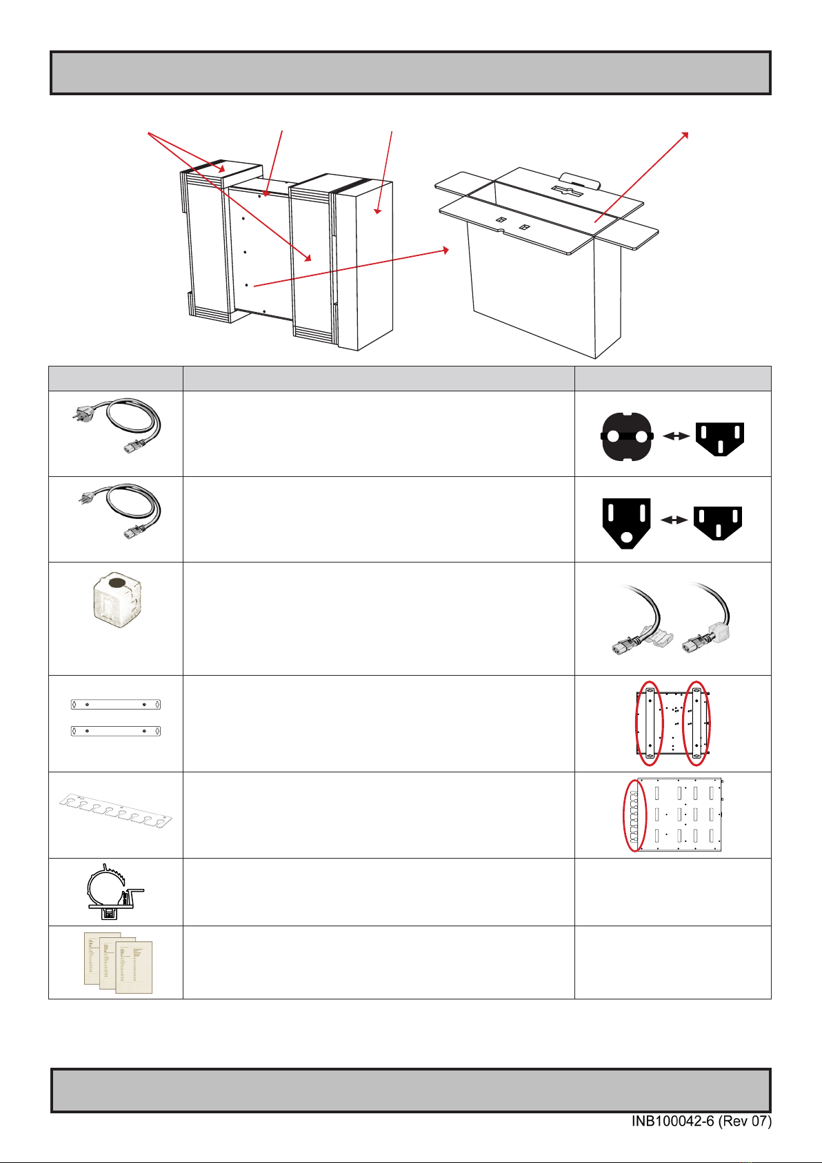
Contents of package
Item Description Illustration
702002605
1 x Power Cable European Type F “Schuko” to IEC.
Length 1.8m
EUR TYPE F
IEC
702002600
1 x Power Cable US Type B plug to IEC.
Length 1.8m US TYPE B IEC
Würth 742 712 21
(1212004518-01)
(split, 10.5mm)
1 x Würth 742 712 21
This ferrite is required when using 100/110/115V AC voltage on the power
supply (not required for 230V AC) to be fully compliant with type approvals.
Review installation chapter for more information.
HT 00226 OPT-A1
Mounting brackets incl. screws (for console mounting)
HT RET STD-A3
Cable Retainer/Relief kit with
3 x Screws M3x4 DIN 965-10.9 Torx BLANK
Cable Relief for DP - kit consists of:
1 x DP cable tie (1990025128S000)
1 x DP cable mounting (1990036354S000)
1 x screw M3x5 (1930006255-01)
Test Reports papers:
1 x Product Declaration TBD
1 x Computer Checklist TBD
1 x BurnInTest Certificate TBD
Stratocell packaging foam HTC03 computer Accessories Box (Contains items as listed below) Outer Box
Contents of package
7
IND100207-21
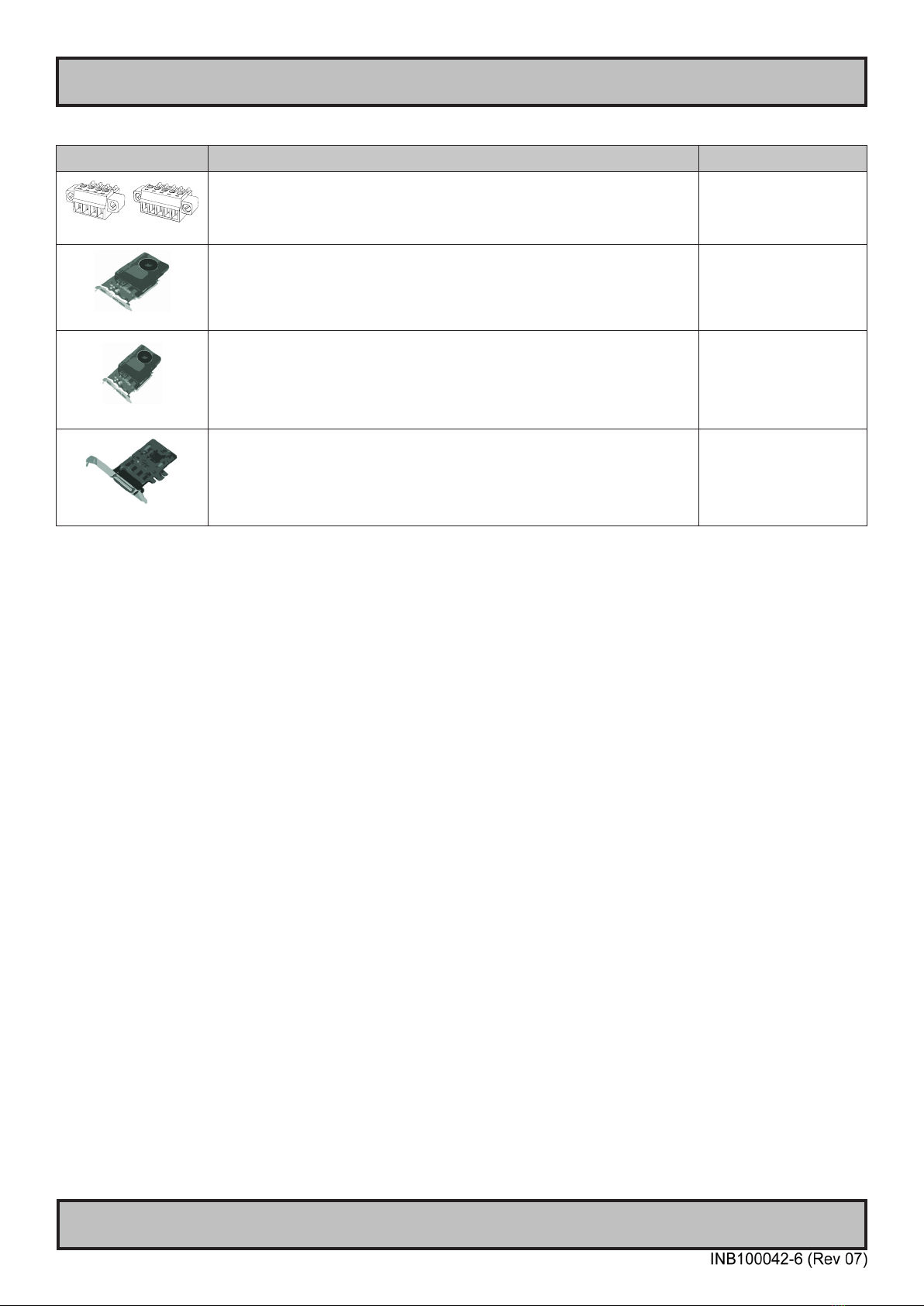
Package may also include: (based on accessories/options ordered)
Item Description Illustration
Tx- Tx+ COM Rx- Rx+
Terminal Block Connectors
Depending on factory mounted options, connector kit as follows:
2 x 4-pin Terminal Block 3.81 for CAN Interface (ZIA0001310-B / ZIA0001310-SLCAN)
4 x 5-pin Terminal Block 3.81 for RS-422 / RS-485 NMEA 4 Channel (PCA100828-1)
4 x 5-pin Terminal Block 3.81 for Digital Input/Output (PCA100297-1)
PNY NVIDIA Quadro P2200
1 x Installation guide
1 x DP to DVI-D (SL) Adapter
Not available for Multi-Power models
PNY NVIDIA Quadro P620
1 x Installation guide
1 x DVD with drivers/support software
4 x mDP to DP adapter*
or 4 x mDP to DVI (SL) adapter*
*Depends on ordered conguration
Not available for Multi-Power models
CP114EL-I
1 x MOXA Cable with 4 ports

8
This page left intentionally blank

9
General

10
IND100078-81
General
IEC62368 policy - Introduction
Safety Instructions
Please read and understand the material in the manual in its entirety before doing any installation/servicing/upgrades.
Personnel who are allowed to do work on the unit is detailed in the “IEC62368 policy for Hatteland Technology
product” section later in this manual. Symbols pertaining to different personnel in regard to operations is described in
the user manual.
Based on requirements EN 62368-1:2014 and IEC 62368-1:2018
Authority Description
Children This equipment is not suitable for use in locations where children are likely to be present.
Ordinary person/
Sailor/End-User
Not allowed to open unit.
Not allowed to install the unit.
Not allowed to terminate/connect cables to the unit.
Instructed person Allowed to open hatches/latches which does not require tools, such as Disktrays.
Allowed to open "battery-hatch" to change the battery even if tools are required.
Allowed to install the unit.
Allowed to terminate/connect cables to the unit indoors.
Skilled person Allowed to open and disassemble the unit.
Allowed to install the unit.
Allowed to terminate/connect cables to the unit indoors and outdoors.
Allowed to terminate/connect earth/ground wire.
Note: Be aware that additional denition for “skilled person” may apply, country dependent.

11
Hatteland Technology AS
IND100077-1
General
About this manual
The manual contains electrical, mechanical and input/output signal specications. All specications in this manual,
due to manufacturing, new revisions and approvals, are subject to change without notice. However, the last updated
and revision date of this manual are shown both on the frontpage and also in the “Revision History” chapter. This
user manual is a standard/general manual that applies to all variations of its product family, i.e. deviation from actual
conguration may exist.
About Hatteland Technology
Hatteland Technology is the leading technology provider of specialized display and computer products, delivering high
quality, unique and customized solutions to the international maritime, naval and industrial markets.
The company represents innovation and quality to the system integrators worldwide. Effective quality assurance and
investment in sophisticated in-house manufacturing methods and facilities enable us to deliver Type Approved and Mil
tested products. Our customer-oriented approach, technical knowledge and dedication to R&D, makes us a trusted
and preferred supplier of approved solutions, which are backed up by a strong service network.
www.hattelandtechnology.com
You will nd our website full of useful information to help you make an informed choice as to the right product for your
needs. You will nd detailed product descriptions and specications for the entire range on Displays, Computers and
Panel Computers, Military solutions as well as the range of supporting accessories. The site carries a wealth of
information regarding our product testing and approvals in addition to company contact information for our various
oces around the world, the global service locations and the technical help desk, all ensuring the best possible
support wherever you, or your vessel, may be in the world.
Contact Information
Head oce, Aksdal / Norway:
Hatteland Technology AS
Eikeskogvegen 52
N-5570 Aksdal, Norway
Switchboard:
Tel: +47 4814 2200
mail@hattelandtechnology.com
Sales oce, Frankfurt / Germany:
Hatteland Technology GmbH
Werner Heisenberg Strasse 12,
D-63263 Neu-Isenburg, Germany
Uwe Scheumann:
Tel: +45 2463 9565
Elke Freisens:
Tel: +49 173 6174753
Sales oce, Oslo / Norway:
Hatteland Technology AS
Strandveien 35
N-1366 Lysaker
Norway
Switchboard:
Tel: +47 4814 2200
mail@hattelandtechnology.com
Sales oce, Aix-en-Provence / France:
Hatteland Technology SAS
Actimart- 1140, rue Ampère, CS 80544
13594 Aix-en-Provence, Cedex 3
France
Mehdi Bounoua (Sales Director Europe, Middle East & Africa):
Tel : +33 6 88 33 64 93
Sales oce, Vista / USA:
Hatteland Technology Inc
450 South Melrose Drive,
Suite #107
Vista, CA 92081
USA
Donna Pallonetti:
Tel: +1 858-282-0659
Fax: +1 858-408-1834
For an up-2-date list, please visit https://www.hattelandtechnology.com/contact
12
Computers
IND101057-28
General
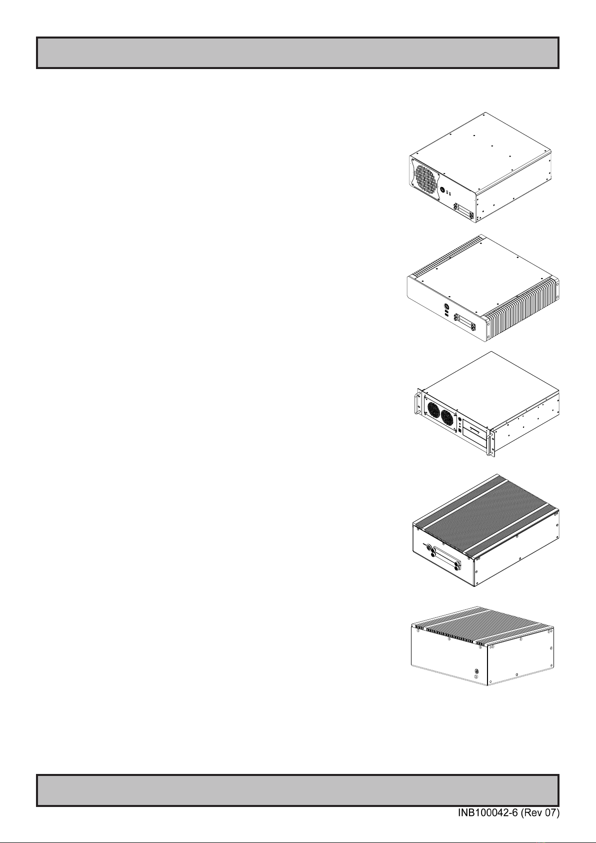
Computers introduction
Hatteland Technology’s range of type-approved computers is designed to
perform in harsh environments while providing the performance and flexibility
you expect. We offer rack mount and black box/standalone computer solutions
for every need. Our computers are used by system integrators, boat builders
and end-users and can be found on all vessel types, all over the world.
If you are looking for a high quality computer for navigation, monitoring or
entertainment solutions, Hatteland Technology can fulfil your high expectations
at a reasonable cost.
Our computer range covers all eventualities and requirements. We offer a wide
range of processor choices, SSD storage and power options, and solid state
technology, neatly engineered within industry standard form factors such as 19”
rack mount, 2U and 4U solutions.
We continually develop our computers portfolio to make the best use of emerging
computer technology so you can be sure that your Hatteland Technology
computer offers the power needed to run modern applications, with the flexibility
to be installed wherever you want, for any marine use.
Designed to perform in harsh environments...
13
Product Labels (Examples)
General
IND100240-16
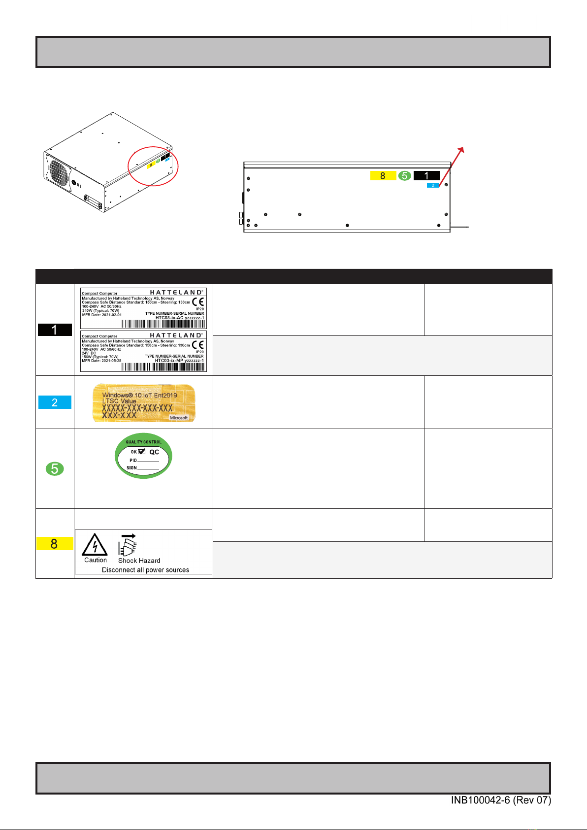
Product Labels (Examples)
Label Size and Types
ID Label Layout Description Specication
Type : Serial Number Label
Name : Label B
Size : 60mm wide x 22mm high (rectangle size)
Note: Text content of label will match specications
derived from Data Sheet.
Silver with glue on back, non-
tearable and made for thermal
transfer printing.
Barcode type: CODE128 (used extensively world wide in shipping and packaging
industries. The symbology was formerly dened as ISO/IEC 15417:2007.)
Type : Operating System (OS) label.
Size : 22mm wide x 9mm high (rectangle size)
Note: Label only present if OS was part of factory
option order. Linux OS does not have any label.
As per delivered from supplier.
Label applies for:
Windows® 10 IoT Enterprise
Type : Quality Control (QC) Label
Size : 30mm wide x 23mm high (oval size)
This label indicates that the unit is produced, tested and
packed according to the manufacture’s QA specications.
It will include a Personal ID and signature by the
personnell responsible for approving the unit in
production, test and warehouse departments.
FLEXcon®PHARMcal®V 400 F
WhiteTC-848V-23 TRACrite™150
Label only applicable for
Multi-Power (AC+DC) models
Type : Shock Hazard Caution Label
Name : Label B
Size : 60mm wide x 20mm high (rectangle size)
Silver with glue on back, non-
tearable and made for thermal
transfer printing.
Rules specied in IEC62368-1:2018 chapter 5.7.6. Applies for units with Dual/Multi-Power
inputs only (more than 1 Power Input).
Only present if the unit was delivered with factory installed Operating System (OS) such as
Microsoft® Windows® Embedded Enterprise. The same Product Key is also printed on the
“Product Declaration” sheet that follows the unit, check contents of package. Note: For certain OS,
there is no physical Product Key Label required or a Product Key Number that must be entered
during installation / usage of the unit.
14
Product Labels (Examples)
General
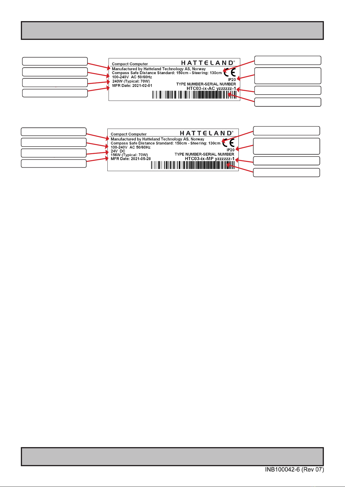
IND100240-16
Serial Number Label Layout Example
Please note that typenumber shown above is a generic sample only. May not reect products mentioned in this manual. Please review
actual product S/N label.
Label Size: 6cm x 2cm. Silver background with black text
Manufacturer/Country
Input Voltage(s)
Type+Serial Number
Barcode (TYP+SNO)
Power Rating Max/Typ
Date of Production (YYYY-MM-DD)
Compass Safe Distance
IP Rating
Lowest value used, higher may apply,
check specications.
Quality Control (QC) Label
This label indicates that the unit is produced, tested and packed according to the manufacture’s QA specications. It
will include a Personal ID and signature by the personnel responsible for approving the unit in production, testing and
warehouse departments.
Label Size: 6cm x 2cm. Silver background with black text
Manufacturer/Country
Input Voltage(s)
Type+Serial Number
Barcode (TYP+SNO)
Power Rating Max/Typ
Date of Production (YYYY-MM-DD)
Compass Safe Distance
IP Rating
Lowest value used, higher may apply,
check specications.

15
Installation

16
Installation
IND100210-19
General Installation Recommendations
Installation and mounting of computers
1. Units may be intended for various methods of installation or mounting (rack mounting, panel mounting,
bracket mounting, ceiling/wall mounting); for details, please see the relevant mechanical drawings.
2. Adequate ventilation is a necessary prerequisite for the life of the unit. The air inlet and outlet openings must
denitely be kept clear; coverings which restrict ventilation are not permissible. The product might be without
any ventilation aperatures which means pt.2 does not apply.
3. Exposure to direct sunlight can cause a considerable increase in the temperature of the unit, and might under
certain circumstances lead to overtemperature. This point should already be taken into consideration when
the bridge equipment is being planned (sun shades, distance from the windows, ventilation, etc.)
4. Space necessary for ventilation, for cable inlets, for the operating procedures and for maintenance, must be
provided.
5. To further improve the cooling of the unit we recommend installing Cooling Fans underneath blowing upwards
into the unit air inlet. This may be required in high temperature applications and also when there is reason to
expect temperature problems due to non-optimal way of mounting.
6. Products with AC input shall be grounded to protective Earth (Safety Ground) when necessary via the bolt
(usually on terminal plate) available on the product.
Products with DC input shall be grounded to protective Earth (Safety Ground) via the bolt (usually on terminal
plate) available on the product. A shorter and thicker cable gives better grounding. A 6mm² is recommended,
but a 4mm² or even 2.5mm² can be used for this purpose.
7. Expose to heavy vibration and acoustic noise might under certain circumstances aect functionality and
expected lifetime. This must be considered during system assembly and installation. Mounting position must
be carefully selected to avoid any exposure of amplied vibration.
8. Additional rules may apply to certain procedures where the symbols and are present. For more
information, review “IEC62368 policy for Hatteland Technology product” section later in this manual.

17
General Installation Recommendations
Installation
IND100210-19
General mounting instructions
1. The useful life of the components of all Electronics Units generally decreases with increasing ambient
temperature; it is therefore advisable to install such units in air-conditioned rooms. If there are no such
facilities, these rooms must at least be dry, adequately ventilated and kept at a suitable temperature in order
to prevent the formation of condensation inside the unit.
2. With most Electronic Units, cooling takes place via the surface of the casing. The cooling must not be
impaired by partial covering of the unit or by installation of the unit in a conned cabinet.
3. In the area of the wheel house, the distance of each electronics unit from the magnetic standard compass or
the magnetic steering compass must not be less than the permitted magnetic protection distance. This
distance is measured from the centre of the magnetic system of the compass to the nearest point on the
corresponding unit concerned. The exact distance is often mentioned in the specic product specications.
4. Transportation damage, even if apparently insignicant at rst glance, must immediately be examined and be
reported to the freight carrier. The moment of setting-to-work of the equipment is too late, not only for
reporting the damage but also for the supply of replacements.
5. The classication is only valid for approved mounting brackets provided by Hatteland Technology. The unit
shall be mounted stand-alone without any devices or loose parts placed at or nearby the unit. Any other type
of mounting might require test and re-classication.
6. Additional rules may apply to certain procedures where the symbols and are present. For more
information, review “IEC62368 policy for Hatteland Technology product” section later in this manual.
Cables
Use only high quality shielded signal cables. For RGB/DVI cables use only cables with separate coax for Red, Green
and Blue.

18
IND100210-4
General Installation Recommendations
Installation
Unit Upgrade Precaution Note
Users which needs to open the unit to expose and reveal electronics, make sure that prior to touching / removing
parts, proper ESD measurements must be taken!
1. Operator should ground himself by using a wrist band.
2. The wrist band should be connected to ground via a ground cord.
3. A one megaohm resistor, installed in the wrist connection end of the ground cord, is a safety requirement.
4. Hatteland Technology recommends to use an Static-dissipative ESD work mat positioned at the workplace. The
3M™ 8501 Portable Field Service Kit is a good choice for this purpose. Make sure that the mat, operator and product
is wired/grounded together.
All assisting persons who might come into contact with the endangered boards must also use the ESD equipment.
CAUTION
This unit contains electrostatic sensitive devices.
Observe precautions for handling.
19
IND100210-56
General Installation Recommendations
Installation
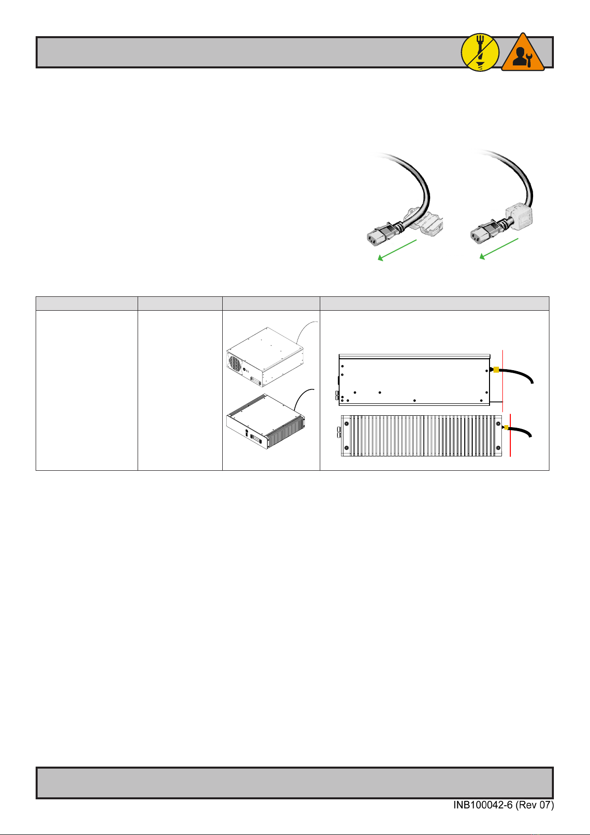
Ferrite
The ferrite prevents high frequency electrical noise (radio frequency interference) from exiting or entering the
equipment. This ferrite is required when using 100/110/115V AC voltage on the power supply (not required
for 230/240V AC) to be fully compliant with type approvals.
The ferrite should be mounted (clipped in place on the cable) and
located as close as possible to the connector piece that connects to
the rear of computer.
When ready: Open the ferrite, place the cable inside as shown in
FIG1, and then gently close it until a click can be heard (FIG2). You
may close and re-open them as many times as required during the
installation.
Typenumber Ferrite Type Dimetric View Perferred distance of ferrite. Side view.
HTC03 xx-yy-zzzzzzz
HT20370 xx-yy-zzzzzzz
1 x Würth 742 712 21 Red Line indicate 5cm [1.97 inch] limit from connector. Do not
mount ferrites (orange square) located beyond the red line!
FIG1
To computer
FIG2
To computer
20
General Installation Recommendations
Installation
IND100210-20
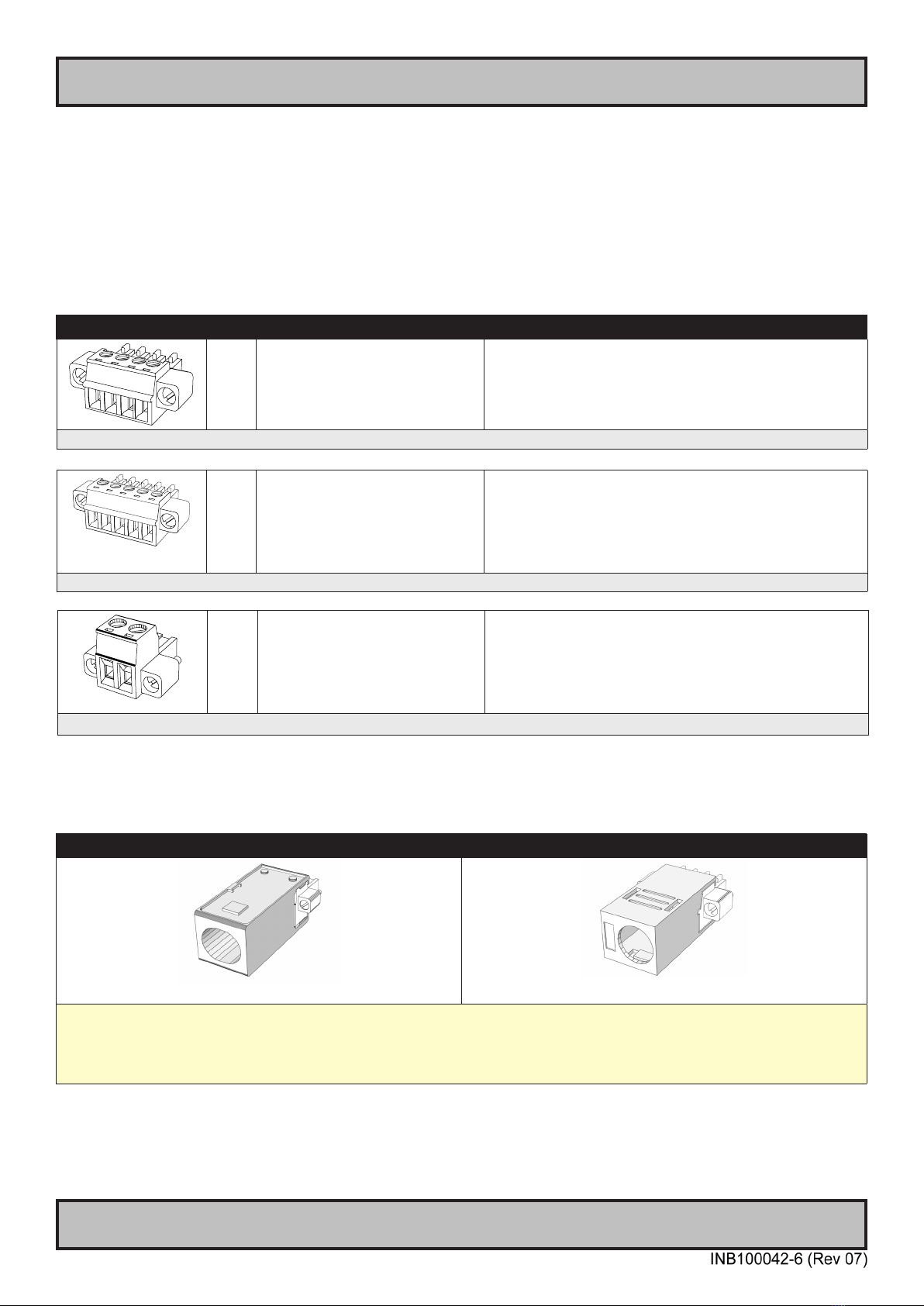
Housing / Terminal Block Connector Overview
Housing / Terminal Block connectors are available in dierent sizes (example 2-pin, 4-pin, 5-pin) which plug into the
connector area of the unit. They are mounted by factory default and delivered with the unit. The housing / terminal
block connectors have steering rails, which ensures that it can not be mounted wrong. The color of these connectors
may vary between black, green and orange depending on manufacturer. You may use approved equivalents of these
connectors, but note that the warranty will be void if any damage would occur to either the unit’s original PCB terminal
socket connector or inside the unit (electronic components, boards etc.). The table below is applicable for any
Series X products, such as Display and Panel Computers, including newer type of Stand-Alone Computers.
Illustration Pins Manufacturer Details Connector used for module
If your installation require additional cable fasteners support, please use the provided Cover Hood and Cable Housing
shipped with the unit for accessories (contents of package). Illustrations below are approximate, actual Housing and
Hood may deviate slightly, but function remains the same.
5-pin Cable Housing - Illustration 4-pin Cover Hood - Illustration
KGG-MC 1,5/ 5 (5-pin) BCZ 3.81 AH04 BK BX (4-pin)
For 5-pin:
“https://www.phoenixcontact.com/online/portal/us?uri=pxc-oc-itemdetail:pid=1834372&library=usen&pcck=P-11-02-01&tab=1”
For 4-pin
“http://catalog.weidmueller.com/procat/Product.jsp;jsessionid=B040D5EB6832629E567C884809FDF6C1?productId=(%5b1005290000%5d)”
Tx- Tx+ COM Rx- Rx+
5-pin MC 1,5/ 5-STF-3,81
Screwdriver: SZS 0,4X2,5mm
VDE, slot-headed.
Tightening torque min. 0.22 Nm.
Tightening torque max 0.25 Nm.
• RS-422 / RS-485 NMEA
(PCA200828-1 / PCA100293-1)
• Digital Input/Output (PCA100297-1)
Identi ed on Hatteland Technology product datasheet as:
“Terminal Block 3.81”
4-pin BCZ 3.81/04/180F SN BK BX
Screwdriver: 0.4x2.5mm DIN 5264.
Tightening torque min.. 0.2 Nm.
Tightening torque max. 0.25 Nm.
• CAN Interface (ZIA0001310-B / ZIA0001310-SLCAN)
Identi ed on Hatteland Technology product datasheet as:
“Terminal Block 3.81”
2-pin MSTB 2,5/ 2-STF-5,08 BK
Screwdriver: SZS 0,6x3,5, slot-
headed.
Tightening torque min. 0.5 Nm.
Tightening torque max 0.6 Nm.
• DC Power IN - Single Input
Identi ed on Hatteland Technology product datasheet as:
“Terminal Block 5.08”
This manual suits for next models
1
Table of contents
Other EMBRON Desktop manuals

EMBRON
EMBRON HATTELAND HD 08T30 Series User manual

EMBRON
EMBRON Hatteland X G2 Series User manual

EMBRON
EMBRON Hatteland Display HT B22G Series User manual

EMBRON
EMBRON HATTELAND HT B30G STC M Series User manual

EMBRON
EMBRON HATTELAND TECHNOLOGY HT C02H STC Series User manual

EMBRON
EMBRON Hatteland HT20 70 Series User manual

EMBRON
EMBRON Hatteland X Series User manual

EMBRON
EMBRON Hatteland E Series User manual


