Tekvox 71021-T1 User manual
71021-T1 Installation Guide
System Description
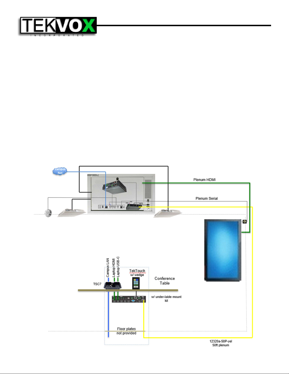
The 71021-T1 Drop-In A/V® system is a complete mediated conference room solution with remote
monitoring and control. The 71021-T1 is optimized for conference rooms with drop ceilings, small tables
and a single flat-screen display. The 71021-T1 is built around an integrated ceiling control unit and a
highly integrated seamless presentation switcher. The ceiling-mounted equipment contains an
HDBase-T receiver with audio de-embedder, a TEK 3 A/V controller, and an audio amplifier installed,
cabled and tested into a 78038 plenum-rated ceiling box. A single premium Cat 6A shielded plenum-
rated cable connects the ceiling unit to the presentation switcher. The supplied cable is certified to
exceed HDBase-T standards and is individually serialized. It is essential to follow approved installation
techniques maintain the extended warranty covering these products.
The 1201-N+ presentation switcher has 5 HDMI, and 1 VGA inputs with mirrored HDMI & HDBaseT
outputs. Control information is carried across the HDBaseT cable between the switcher and the
TekMonitor in the ceiling unit. The pre-programmed TekTouchPad provides simple and consistent room
control. All essential cabling for expeditious and consistent installation is included.
Ceiling - Ceiling Box, Speakers, Occupancy Sensor & Projector
Preparation
The speaker cables provided with the 71021-T1 come in a standard length of 25 ft each. Locate the
ceiling box in a center position in the room that will allow the speakers to be spread evenly and of equal
distance from each other in the room. Avoid placing speakers too close to a wall as they project sound
in a cone shape, and this will reduce their quality of sound. Ensure the location of the ceiling box is
close enough to the video projector that all included cables will reach comfortably.
Ceiling Box
The ceiling box occupies a 2x1 tile space. After removing a ceiling tile, cut it to size, and place the
ceiling box into the plenum. Use the provided ceiling suspension cables to suspend all four corners of
the ceiling box from the ceiling structural members. A licensed electrician will be needed to provide the
ceiling box with electrical power. Pass an ethernet cable through one of the knockout holes in the 78038
ceiling box, using a provided rubber grommet to protect the cable, and connect the TEK 3 to the campus
VLAN.
Speakers
Locate the coiled speaker wire on the ceiling box and move each speaker wire into the desired position
for the speaker placement. A snake tape, or similar electrical wire movement tool may be helpful for
moving speaker wire through the plenum. Once the wire is in place, remove the ceiling tile. Then place
the speaker into the ceiling and, using 1 ceiling suspension cable per speaker with the corner tabs,
secure it into the plenum. Then attach the speaker cables to each speaker with the provided wire nuts.
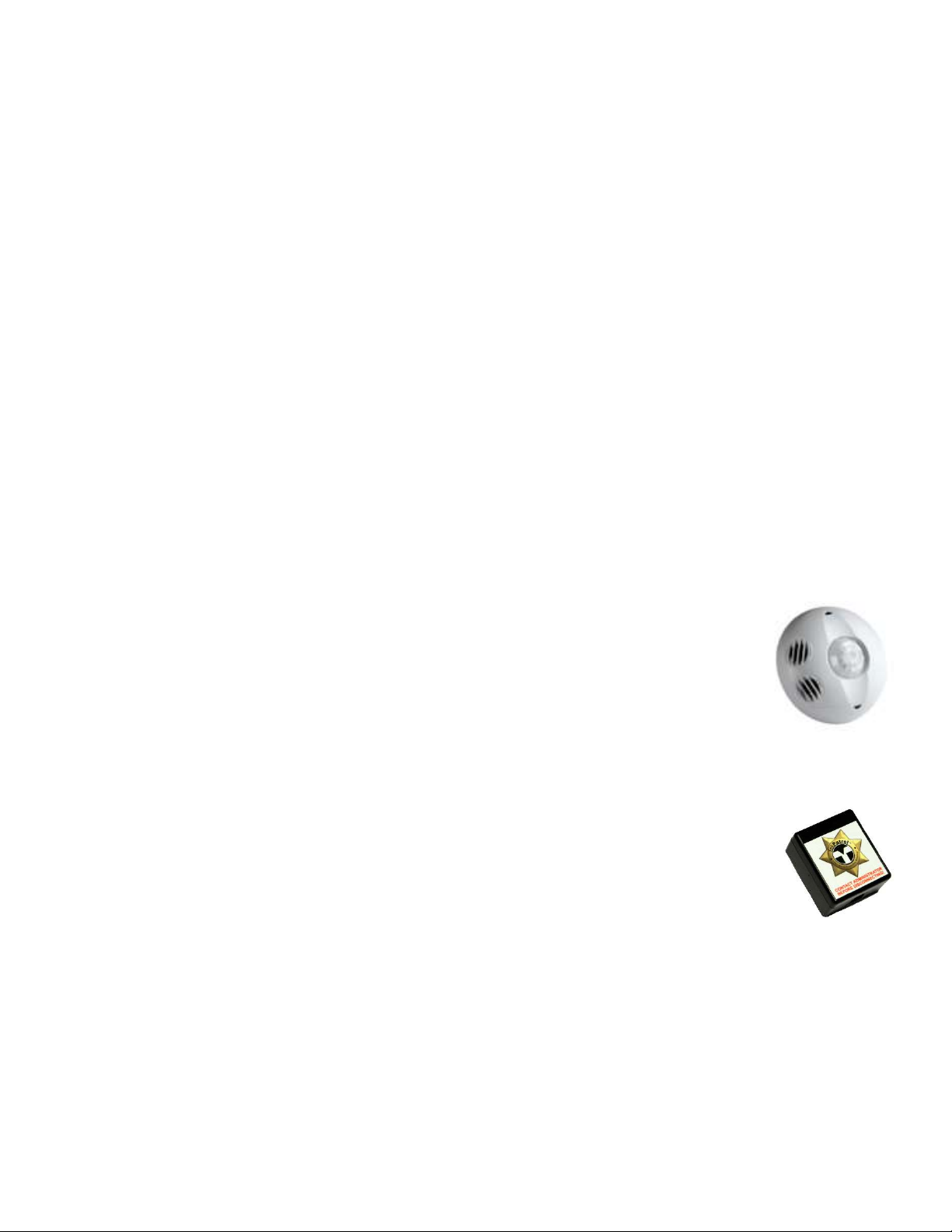
Occupancy Sensor
When installing the occupancy sensor, it is best to place it behind or above the room
entrance and face the vents towards the conference table. Make certain there are no
air vents within 4 feet of the sensor, and that no air is blowing across it. Pass the
occupancy sensor cable through one of the knockout holes in the 78038 ceiling box,
using a provided rubber grommet to protect the cable, and wire as shown on the cable
label.
Wall – Plenum HDBaseT Cable
Flat-panel Display
Install display on wall where desired. From ceiling control unit, run plenum HDMI and
RS232 cables along structural members to directly above display location. Using a
push-rod or fish-tape, run the cables down the wall and directly behind display. Connect
HDMI cable to display input and RS232 to control port, ensure cables are not under
tension, and use provided Velcro pad to adhere TekSecurity module to the rear of the
display without obstructing mount articulation.
Plenum HDBaseT Cable
When working with and installing plenum HDBaseT cable, DO NOT bend cable with a tighter turn
radius than 3”, as this will seriously damage the cable and necessitate its replacement. Running along
the structural members in the plenum, pass the cable from the HDBaseT receiver to a point in the
ceiling directly over the location at which the cable routing meets the wall. Using a push-rod or fish-
tape, run the HDBaseT cable down the wall and out the routing hole for the cables. Leave the HDBaseT
cable in the intended location of the 1201 presentation switcher. Ensure that all cable is routed safely
along the bottom surface of the conference table to avoid damage from foot traffic or rolling chairs. All
excess HDBaseT cable should be neatly coiled in the ceiling in a service loop.

Conference Table – Cable Housing, Switcher, Amplifier & TekTouchPad
TSC7 Cable Housing
Locate a position within comfortable reach from all seated positions at the conference table. Using the
included cutout template, cut a hole for mounting the cable housing. Insert the cable housing into the
table and attach the included mounting flanges into the highest accessible slot on each end of the
underside. Turn the thumb-screws until both feet are snug against the underside of the table, and the
cable housing does not move. Run all user cables through the central opening in the cable housing,
using one circular cutout per cable. Once all cables are in, insert the included central plate and secure
at both ends using the provided screws. To protect the cables from damage, snap one plastic grommet
into each hole in the cable housing.
1201-N+ Presentation Switcher
Attach the under-table mounting wings (included in switcher accessory box) to the 1201-N+ and fasten
to the underside of the conference table, as near as possible to the cable egress. Connect power cable
to rear of 1201-N+ and run to nearest outlet, routed so that the cable does not block other connections
or dangle from table underside. Connect all user cables to the switcher’s HDMI inputs as labelled.
Connect to yellow HDBaseT cable to the 1201 presentation switcher’s HDBT output prt.
TekTouchPad
Find a place within comfortable reach from all seated positions at the conference table to place the
mounting wedge for the TekTouchPad. Using a pencil, LIGHTLY trace a 4 ¾” tall by 2 7/8” wide
rectangle. In the approximate center of the rectangle, drill a 5/8” diameter hole for the TekTouchPad
cables to pass through. Using the traced rectangle as a guide, attach the wedge to the table using the
4 provided wood screws. Attach the rectangular back plate, with mounting posts facing outward and
“Top ↑” text facing upward, using the two provided flat screws. Run the TekTouchPad cable from the
1201 switcher up through the previously drilled hole and connect to the back of the TekTouchPad.
Ensuring wider portion is facing down, press TekTouchPad firmly onto 4 mounting posts. Remove
protective film once fully assembled and secure.
Table of contents
Other Tekvox Conference System manuals

Popular Conference System manuals by other brands


Polycom
Polycom RealPresence RMX 4000 Installation & quick start guide

Shure
Shure CU 6110 user manual

Biamp
Biamp Crowd Mics Network administrator's guide

StarLeaf
StarLeaf GTm 5250 installation guide

AKE
AKE PowerCom plus Series Operating and installation instructions

Garmin
Garmin inReach MINI quick start guide